Line following robot
Grade 6
Presentation
Hypothesis
If a line tracking robot is equipped with high sensitivity photoelectricsensors to detect a line on a surface then the robot will be able tosuccessfully follow the path of the line, maintaining a consistent anduniform speed provided that the tracked line is clear and thick and havecurved corners.
Research
Line tracking robots are autonomous machines that detect and follow aline or path, often using sensors. The line can be simple, like a black lineon a white surface, or more complex with multiple paths. The sensorsallow the robot to sense the line and the motors allow the robot tomovein the direction of the line based on the sensor input. If the line ends, therobot will take no input giving itself a signal that the line is finished and ithas to stop.
Variables
Manipulated Variable : Input detected by the photoelectric sensors on the linetracking module. Depending on the detection of light by photoelectric sensors onthe line tracking module the input values of the sensor changes. The inputchanges with thickness of the lines, curvature, color of the line etc. Lower valuesdetected by the sensor mean that its detecting black line and higher values meanthat its detecting other lights which helps in tracking the black line. If the line isnot thick then robot will move slowly until the thickness is increased again. Controlled Variable: Power supply The power supply to all components including DC motors, DC motor drive and linetracking module is kept constant throughout the experiment. Responding variable : Motor Speed The rotation speed of the DC motors, and in turn the wheels of the robot, is variedin response to the quality of the tracked path. If the tracked line is thick and clearthen robot will follow it smoothly with uniform speed, however, if the line is thinor broken or the corners are too sharp then the robot will take time to track thepath and therefore its speed will also reduce.
Procedure
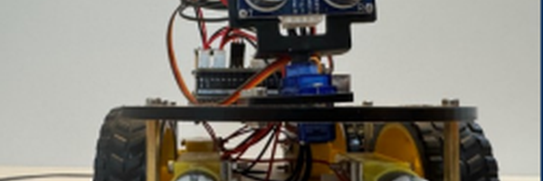
Following procedure was used for the implementation: 1. Attach the four DC motors on one side of the bottom plate assembly of the chassis 2. Attach the ‘line tracking module’ on the other side of the bottom plateassembly such that it faces the ground for the detection of black line3. Attach the Arduino Arduino controller controller and the IO expansion expansion board together together byinserting the pins of IO expansion board into the Arduino controller 4. Once the Arduino controller and IO expansion boards are merged, attach them on the top plate assembly of the chassis 5. Attach the battery on the top plate assembly of the chassis. Thebattery assembly can be charged using a usb cable and the battery canbe turned on and off via a switch 6. Once all the components are physically mounted on the chassis, wires fromthe following components are connected to Arduino controller board via theIO expansion board so that the Arduino controller can provide power andsend/receive control signals to/from all the components using the code: I. Wires from line tracking module II. Wires from battery III. Wires from each DC motor 7. After the wiring, wiring, bottom and top plates are joined together together using nuts andbolts 8. The four wheels are assembled to the shafts of each DC motor 9. The code is written as per the description provided and uploaded on theArduino controller board using Arduino software that is installed on acomputer. The Arduino board has a switch that can be toggled betweenupload and function mode. Code can be uploaded using a USB cable in theupload mode. 10. There is also a mode switch on the Arduino board that can be used to switchbetween different modes. Currently only ‘line tracking mode’ is implemented. This feature is for future expansion and requires more coding and otherhardware components.
Observations
We viewed that the robot has certain issues when coming across sharp turns, needing more rounded corner for optimized movement / tracking
Analysis
Code is written in C++ programming language and loaded on the Arduinocontroller board via the USB cable. The code can be written in theprogramming software that is provided by Arduino Following functions are achieved by the code: 1. There are three photoelectric sensors on the line tracking module - R(Right), R(Right), M(Middle), M(Middle), L(Left) L(Left). The code configures configures these 3 sensors sensors asinputs and stores the values detected by these sensors for predictingthe direction of the line tracking robot 2. The code detects different input values from the photoelectric sensorsdepending on the change in environmental data and how much lightintensity the sensor detects 4. Based on the above logic, the code defines different photoelectricsensor ranges that decide whether the sensor is detecting black line orif it is lifted up. The lower range means the sensor detects black lightwhereas the higher values mean that it detects other colors meaningthat the robot is either lifted in the air or there is no black line. 4. 4 conditions are covered by this code: I. The robot is lifted in the air and stops all motion II. The middle sensor is on the black line and therefore robot movesstraight forward III. The right sensor is on the black line but the left one is not instraight forward III. The right sensor is on the black line but the left one is not inwhich case the robot moves right to keep tracking the line IV. The left sensor is on the black line but the right one is not inwhich case the robot moves left to keep tracking the line V. Both left and right sensors are not on the black line and thereforerobot goes into search mode periodically moving left and right to search for the line
Conclusion
After testing different curvature and line thickness we have come to theconclusion that a line tracking robot requires a curved corner, thick clearline to be able to follow it with a uniform speed.
Application
Line tracking robots have many applications in the real world: •Automated transportation •Packing Packing and assembling assembling day to day items •Helping harvesting agriculture •Acting as security on a determined path •Playing a main role In space exploration
Sources Of Error
Sharp turns, thin lines cause speed and accuracy to deplete
Citations
1. https://intorobotics.com/line-follower-robot-techniques-and-t echnologies/ 2. https://technologyrealmresources.com/2024/09/13/how-do-followthe-line-coding-robots-actually-work/ 3. https://www.instructables.com/Line-Follower-Robot-With-ArduinoReally-Fast-and-R/ 4. https://playwithcircuit.com/line-follower-robot-usingarduino/#google_vignette 5. https://www.indmallautomation.com/what-are-the-applications-ofphotoelectric-sensors-in-robotics/ 6. https://www.futurelearn.com/info/courses/robotics-with-raspberrypi/0/steps/75899 7. https://docs.arduino.cc/hardware/uno-rev3/ 8. https://www.instructables.com/Driving-Small-Motors-With-theTB6612FNG/
Acknowledgement
Not applicable