Leveraging Glenn-Research Copper for Integration in Pressurized Water Reactors (PWR)
Richard Gao
Webber Academy
Grade 11
Presentation
Problem
1. Introduction 1.1. Economical Barriers to Nuclear Energy Nuclear fission has been an influential technology in the energy sector, with high energy outputs and small amounts of waste compared to other non-renewable sources [1]. Nuclear reactors produce a substantial amount of energy in countries with access to this technology. Figure 1 depicts the changes in global nuclear energy output from 1970-2022. A significant increase in energy output is shown between 1970-2000, which is accredited to the integration and maturing of generation II and III nuclear reactors [1], [2]. In 2019, the world’s combined nuclear fleet supplied 2821 TWh, enough to power all of the United States’ homes for more than a month [3]. China is the leading investor in this technology, with 30 new reactors under construction totaling an electrical capacity of 32 GWe [1]. Most of the world’s nuclear fleet consists of pressurized water reactors (PWRs) [4]. However, investors are reluctant to fund nuclear research and development, largely due to the high construction costs, significant risk factors, long payout times, short operational lifespans, and history of nuclear failures [5], [6]. Such disincentives inhibit the development and implementation of generation III+ and IV reactors, which are defined by upgrades to safety, efficiency, or energy output [7]. The jump from the creation of the first generation of reactors to the advent of generation II reactors only took 10 years, from 1960-1970. However, up to this day, most of the world’s nuclear fleet are generation II or III PWRs and boiling water reactors (BWRs), with a few generation III+ equivalents undergoing construction and implementation [2]. The stagnation in energy output since 2000 evident in figure 1 is likely attributable to the lack of generation III+ and IV reactors in operation. One factor contributing to the stalling in funding of nuclear reactors is that the construction of reactors accounts for a large percentage of the total cost of operation [5]. In 2022, the annual costs of newly constructed reactors, including fuel, maintenance, and operating costs, only amounted to 20 percent of the reactor’s levelized cost (cost per GWe) [4], [5]. This, combined with the material challenges to fission (1.2) that inhibit its operational lifespan, tends to make investors reluctant to invest in the technology. Previous accidents such as Three Mile Island, Chernobyl, and Fukushima have strong correlations with the decrease in funding for nuclear energy [6]. Figure 1 also illustrates the decline in total energy output following the 2011 Fukushima accident.
 Fig. 1. Global Nuclear Energy Production [1]. The nuclear energy output in each continent is also provided. Western and Central Europe, South America, North America, Eastern Europe and Russia, Asia, and Africa’s nuclear energy bars are shown in green, red, dark blue, orange, light blue, and yellow, respectively. Note that Africa’s energy production is negligible for illustration on the graph.
1.2. Structural and Material Impediments to Nuclear Fission Another challenge facing nuclear fission besides economics is finding solutions for damages caused to the reactor from neutron irradiation. Many materials have been proposed, researched, and integrated [8]. Currently, PWRs, a type of light water reactor that transfers heat through pressurized liquid water to avoid vaporization, cannot operate for more than 70 years [4]. Other light water reactors (LWRs) cannot sustain operations for more than 40 years due to material degradation [4], [9]. Most of the physical benefits of a reactor (high power output, self-sustaining) are thus outweighed by the heavy operational burdens on materials. Fuel cladding, heat exchangers, coolant piping, steam generators, reactor pressure vessels (RPV), and electrical wire shielding must be resistant to radiolysis, radiation-induced solute segregation, irradiation creep, void creation, void-induced swelling, corrosion, irradiation-assisted stress corrosion cracking (IASCC), intergranular stress corrosion cracking (IGSCC), fracture, and helium embrittlement for prolonged periods of time [4]. Newer generation reactors are also exposed to higher temperatures and irradiation doses, resulting in the need for more resistant materials for radiation-induced effects [10].
1.2.2. Neutron-Assisted Displacement and Stress Corrosion Cracking Beyond the environmental conditions, the displacements per atom (dpa) is the primary metric used to estimate irradiated-induced damage in a material [4], [11]. This approximation measures the number of displacements experienced per atom on average throughout its lifespan [4], [11]. Although most damaging effects of neutron radiation occur at high dpa values of greater than around 5 dpa, some effects, such as radiation hardening and the curtailment of elongation and fracture toughness, can be pronounced at levels of 0.1 dpa [4]. Thus, elements with high displacement energies for their respective neutron energy range, such as thermal neutrons for PWRs are recommended to minimize the dpa [4]. Irradiation-assisted stress corrosion cracking is a pervasive and challenging obstacle to overcome, having been reported in four reactor designs (including PWRs) and a wide range of structural components such as the fuel cladding, springs, and control rods [4], [12], [13]. IASCC can be classified into two distinct categories: water chemistry and microstructure. Water chemistry effects include radiolysis and change in corrosion potential [4]. Microstructure effects include radiation-induced solute segregation, microstructure dislocations, void swelling and creep, and hydrogen and helium generation, potentially leading to embrittlement [4], [14], [15], [16]. Such factors degrade the material over time to a point where the reactor cannot safely operate.
1.2.3. Nanocrystalline Materials’ Resistance Against Void Swelling The creation of voids is also a common irradiation-induced phenomenon [4], [14], [15], [16]. Such voids generally result in void swelling, which causes a multitude of problems for the material, such as changes in fracture behaviour, embrittlement, thermal conductivity, yield stress, hardening, and anisotropic growth [4], [17]. Void swelling has been reported at a rate of 1% dpa-1, which is problematic for the development of long-lasting materials [17], [18]. In PWRs, where materials can exceed 80 dpa [4], the development of vacancy-resistant materials is pivotal. Nanocrystalline materials have been found to be extremely resistant to void nucleation, growth, and coalescence. [19], [20]. NC materials have been proven to possess better vacancy resistance than their coarse-grained equivalents due to the high density of grain boundaries, which provide excellent defect sinks for pinning dislocations [19], [20]. For example, in the study presented in [20], NC Cu-Ta was exposed to 4 MeV copper ions at various dpa values and temperatures. All ranges showed an abnormally low hardening and swelling compared to most polycrystalline materials. Samples irradiated to 100 dpa only measured 0.2% swelling. Such void-resistant properties are also predicted in other NC alloys [19]. Homologous melting temperatures exceeding 0.3 TM induce grain instability in most NC materials due to nanograin coarsening at high homologous melting temperatures [19], [21], [22]. Grain growth is especially problematic in PWRs due to the decrease in resistance to porosity and the reduction of yield strength, as demonstrated by the Hall-Petch effect [17], [19], [20].
1.3. Insights on Materials Selection for Generation IV and Fusion Reactor Systems
A pivotal step in the advancement of nuclear technology is the search for suitable materials for generation IV and fusion reactor systems. Generation IV reactors are characterized by an increase in energy efficiency, failure impact minimization, accident response time, production of process heat to drive chemical processes, or waste minimization [4]. However, in improving upon these aspects, generation IV and fusion reactors must operate at either greater temperatures or greater neutron fluxes [4], [10].
Figure 2 provides the operating temperature and dpa ranges of several generation IV reactor concepts [4], [10]. Generation II and III reactor operating temperatures and dpa ranges are shown for comparison. Generation IV reactors require materials with much higher temperature ranges and displacement resistance. Thus, current materials used for PWRs are unsuitable for most generation IV and fusion reactors [10]. Additionally, the travelling wave reactor (TWR) is currently under intense study for its ability to convert fertile fuel into usable isotopes [23]. However, its materials are exposed to tremendous amounts of neutron displacement (Fig. 2), causing a curtailment of their lifespans. Hence, the development of new materials for generation IV reactors is critical for increasing their lifespan and therefore attracting investment.
 Fig. 2. Operating Temperature and dpa Exposure Ranges for Generation IV and Fusion Reactors [4], [10]. The reactor types include: very high temperature reactor (VHTR), supercritical water reactor (SCWR), gas-cooled fast reactor (GFR), lead-cooled fast reactor (LFR), molten salt reactor (MSR), sodium-cooled fast reactor (SFR), and fusion reactors, shown in dark blue, purple, yellow, gray, cyan, red, and dark green, respectively. Generation II and III reactor ranges are provided in light green. The travelling wave reactor (TWR) range is illustrated as a green arrow, pointing to further dpa ranges.
1.4. Current use of materials in PWRs Nickel-based alloys and stainless steels are currently primarily used in areas with the highest thermal neutron flux due to chromium’s resistivity to IASCC [4], [24]. However, chromium is vulnerable to radiation-induced embrittlement at temperatures of PWR operation [25]. The selection of materials for nuclear energy is difficult, as the material needs to withstand several modes of radiation for a long time. All radiation-related damaging effects should be considered during the selection of materials. Usually, different materials will have different weaknesses and strengths against different forms of degradation modes [4]. Currently, nickel and austenitic stainless steel alloys are used in the heat exchanger tubing in PWRs because of their combination of high resistivity to many corrosion forms, high strength, and excellent high-temperature performance [4], [26], [27]. However, the thermal conductivity of nickel, chromium, and iron are 91 W/mK, 94 W/mK, and 79 W/mK, respectively, which is problematic for a material intended to conduct as much heat as possible [28]. The choice of using nickel and chromium alloys as heat exchanger tubing is inefficient for the energy transfer between the steam generator and pressurized water tubing, leading to reduced electricity output compared to other materials.
1.5. Usage of Copper and Molybdenum in PWR Heat Exchanger Material Copper has one of the highest thermal conductivity values of all elements of approximately 400 W/mK [28]. Additionally, because of its semi-noble metal properties, it is not easily degraded from corrosion, SCC, void swelling, or other radiation-induced effects [29]. However, copper’s melting point (1085oC) [28] and yield strength (33 MPa) [30] make its performance at high temperatures suboptimal for reactor use. Glenn-Research Copper (GRCOP), a material with a pure copper matrix and Cr2Nb laves, has been used extensively in aerospace, has been found to significantly elevate the strength of copper with minute concentrations of Cr and Nb [31]. This property is mostly attributed to the Cr2Nb precipitates that harden and retard dislocation movement, while retaining the austenitic pure copper body [31], [32]. This study will provide an empirical analysis of the behaviours of GRCOP 84 and 42 in a high temperature environment. Since extensive research has already been conducted on GRCOP, such as [31], [33], the study will prioritize the properties of GRCOP 84 and 42 for thermal, light water reactor use. GRCOP will be milled and characterized structurally and compositionally through x-ray diffraction (XRD). Heat annealing at ___K will be leveraged to predict its behaviors under PWR irradiation environments. The sample will not be undergoing irradiation treatment due to limitations in funding and opportunities. The Stopping Range of Ions in Matter (SRIM) was utilized to simulate the ternary alloy’s performance when exposed to thermal neutrons [34]. The long-term objective of this study is to provide material insights into generation III+, IV, and fusion reactors as well as evaluate the extent to which GRCOP can be implemented in PWRs.
Method
2. Methodology 2.1 Mechanical Alloying Process To assess the characteristics of GRcop, 70 grams of GRcop 84 and GRcop 42 were created. A planetary ball mill (PBM-04, MicroNano Tools, Ontario) was employed in an argon environment (Weldready, Ontario) to prevent oxidization. 99% pure copper (Goodfellow Cambridge Limited, Cambridge), 99% pure chromium (Powders on Demand, Massachusetts), and 99.5% pure niobium (Powders on Demand, Massachusetts) powders were utilized to create an alloy powder. The maximum particle sizes for the powders described above were 50 µm, 45 µm, and 74 µm, respectively. Zirconium jars (MSE Pro 100 mL, MSE Supplies, Arizona) functioned as the alloying vessels containing stainless steel grinding balls (SamplePrep 2154, Cole-Parmer, Illinois) of 6 mm and 10 mm with a mass ratio of 1:4. To suppress severe cold welding, 2.5 wt. % ethanol was chosen as the process control agent for this study. Following the initial mechanical alloying at 350 RPM for one hour, each material was centrifuged at 100 RPM for 30 hours with 15 minute rest periods at the end of every hour. 0.2 g of each material was extracted after 10 hours, 20 hours, and 30 hours of milling. Two 6 mm grinding balls were removed after each extraction. The final sample was subjected to heat treatment at 500oC (Thermo Scientific Lindberg TF55035A-1 Blue M Mini-Mite Tube Furnace, Cole Parmer, Illinois) for two hours. The ball milling process was conducted following the procedure of [35].
2.2 X-ray Diffraction (XRD) To analyze grain sizes, microstrain, and crystalline structures, an X-ray diffractometer (D8 Advance, Bruker, Massachusetts) was harnessed. Each sample extracted from the mechanical alloying process was transferred onto a specimen holder (powder specimen holder, Bruker, Massachusetts) before processing. Each 2θ value was exposed to a Cu Kα x-ray source (λ = 1.5406 Å) for 90 seconds. 0.1-degree 2θ intervals were utilized for this study. Peaks and phases, and figures were generated using GSAS II (Version 5.6.0).
Grain sizes, interplanar spacing, microstrain, and yield strengths were determined using the Debye-Scherrer [36], [37], Bragg [38], and Williamson-Hall [36] equations shown below:
Debye-Scherrer: D=Kλ/(βcosθ) Where:
- D is the grain size
- K is the Scherrer constant. K = 0.9 is widely accepted for non-spherical materials [36]
- λ is the x-ray wavelength (1.5406 Å)
- β is the full width at half maximum (FWHM)
- θ is the Bragg angle
Bragg: n =2dsin Where:
- n is an integer
- λ is the x-ray wavelength
- d is the grating constant
- θ is the Bragg angle
Williamson-Hall: cos = 4sin+KD Where:
- β is the FWHM
- λ is the x-ray wavelength
- ε is the microstrain
- θ is the Bragg angle
- K is the Scherrer constant
- D is the grain size
To calculate the FWHM values, peaks were assumed to follow the Voigt profile, a convolution of the Gaussian and Lorentzian distributions. The FWHM for Voigt distributions can be approximated to within 0.02% accuracy via the equation described in [40], [41]:
βV = 0.5343βL+sqrt(0.2169βL^2+βG^2)
Where βV, βL, and βG are the FWHM values for the Voigt, Cauchy-Lorentzian, and Gaussian distributions, respectively. The FWHM for the Gaussian and Lorentzian profiles were calculated using the standard deviation (σ) and scale parameter (Λ), respectively, where:
G = 22ln(2), and L = 2Λ.
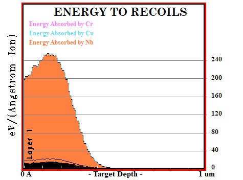
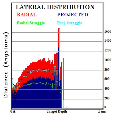
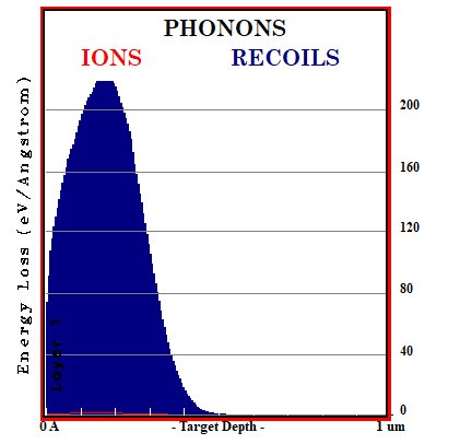
2.3 Stopping Range of Ions in Matter (SRIM) To simulate the effects of thermal neutron irradiation on GRcop, the SRIM (SRIM-2008 Pro) software was implemented to gather insights into the penetrating power of thermal neutrons in GRCop. A target layer of width 1 µm was bombarded with 1 MeV krypton ions to simulate thermal neutron irradiation [34]. Lattice and surface binding energy parameters of each element were calculated by the SRIM software. The displacement energy parameters for copper, chromium, and niobium were 36 eV, 40 eV, and 30 eV, respectively [42]-[44]. After a simulation of the detailed calculation of damage cascades for at least 5000 ion collisions, displacement, ion, recoil, and phonon distributions were retrieved for further analysis.
Analysis
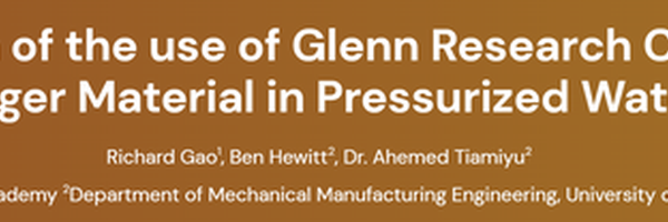
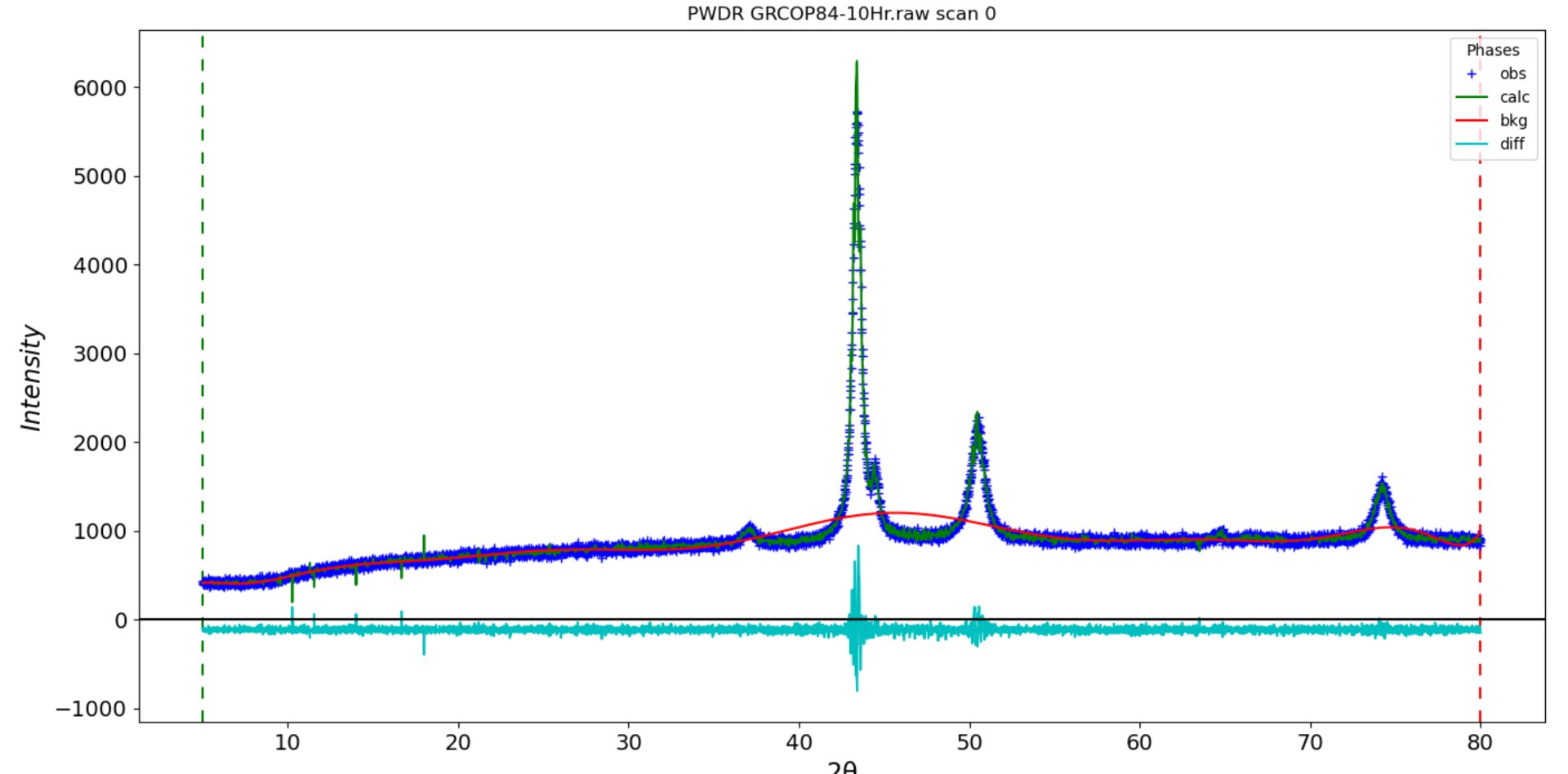
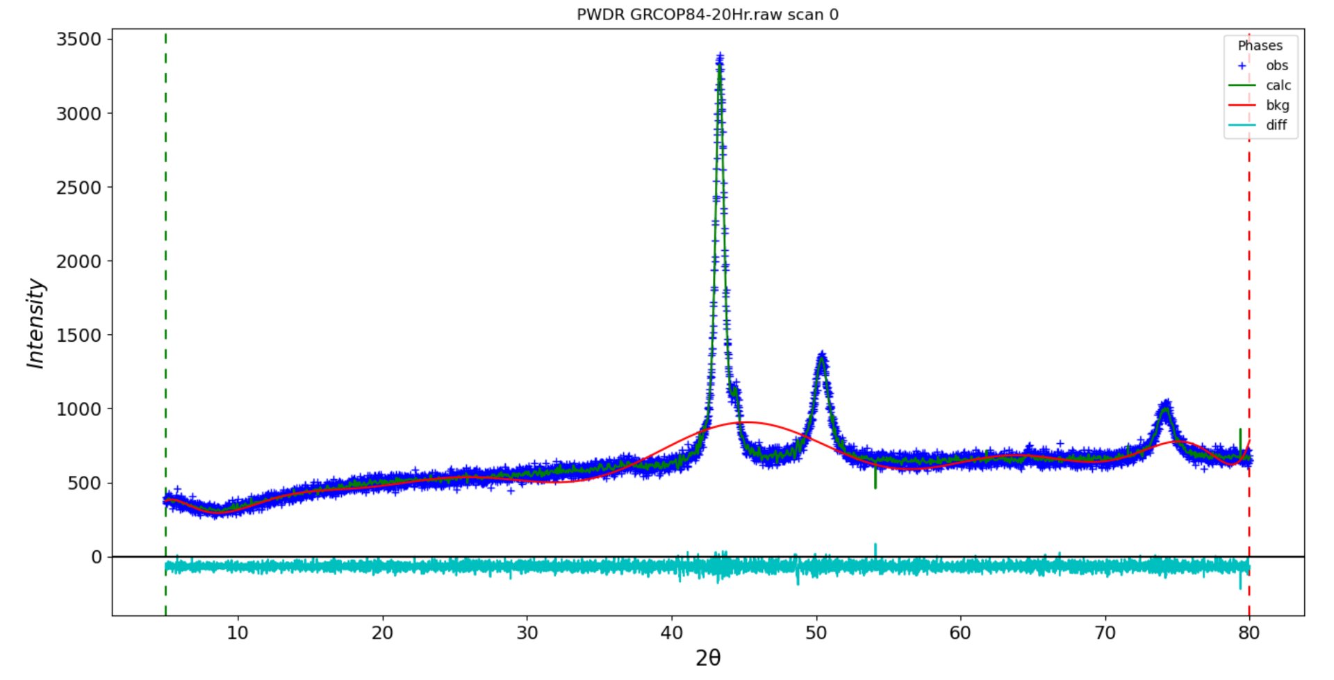
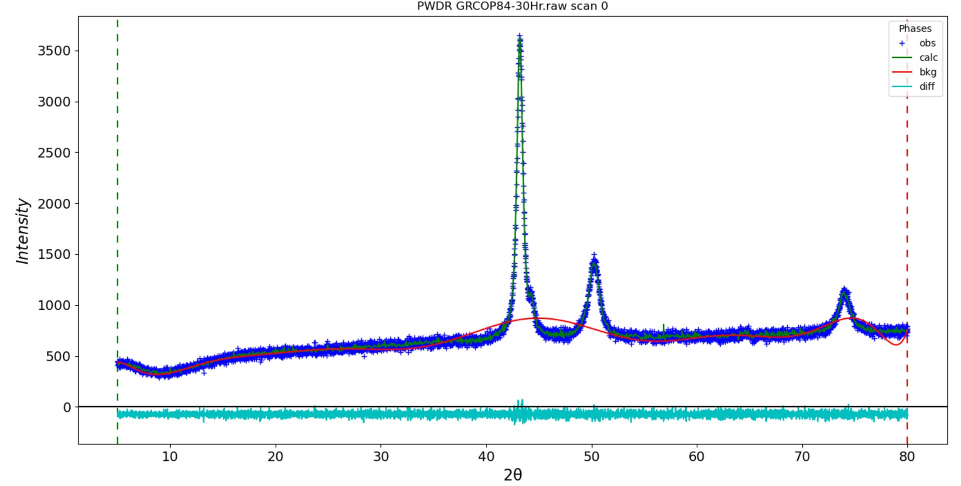
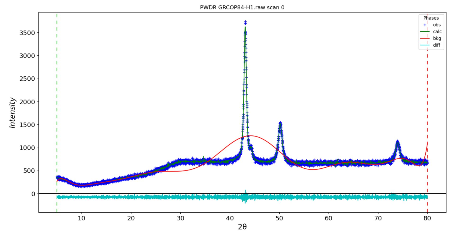
The following graphs are x-ray intensity peaks retrieved from XRD. The 30 hour and heat treated peaks for copper, chromium, and niobium have their Miller indices labeled. Note the gradual disappearance of the 37 degree peak. Some peaks of best fit may be inaccurate from the GSAS II software.
GRCop 42 10 hour sample:
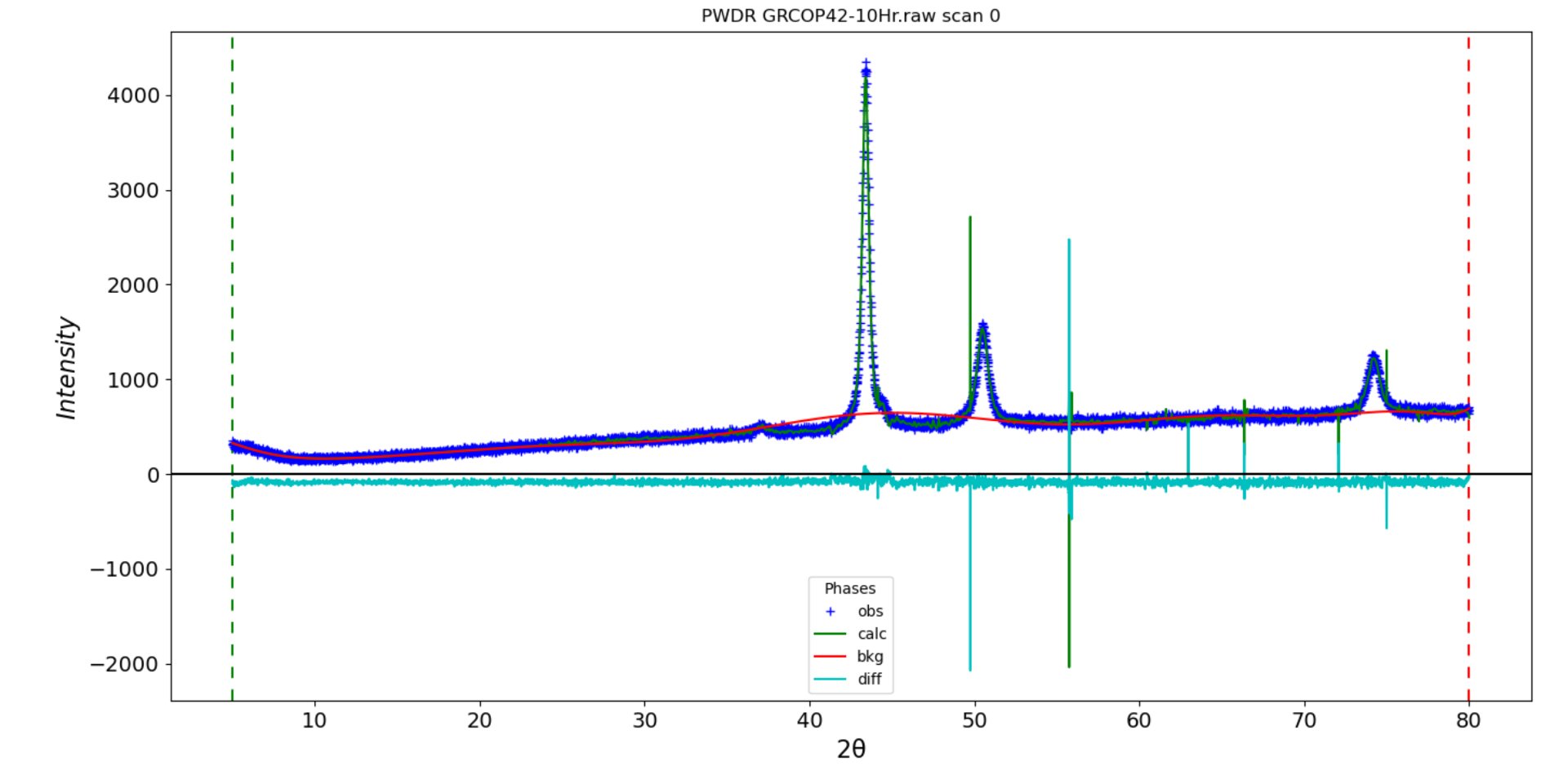
GRCop 42 20 hour sample:
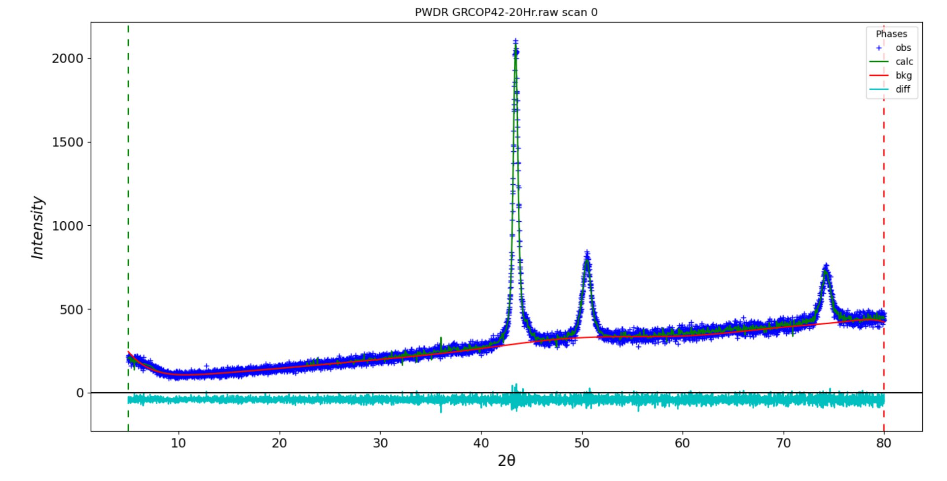
GRCop 42 30 hour sample:
GRCop 84 10 hour sample:
GRCop 84 20 hour sample:
GRCop 84 30 hour sample:
GRCop 84 heat treated sample:
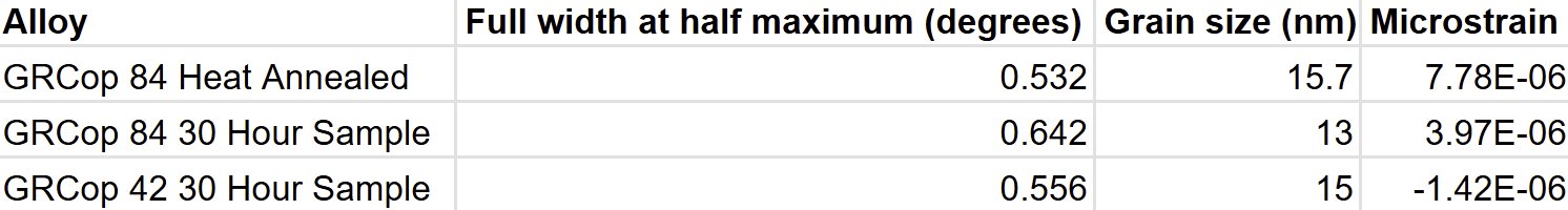
We have calculated the microstrain and grain sizes for the 30 hour and heat treated samples. The table is provided below. Additionally, the grating constants and edge lengths to calculate the hkl family groups are also provided below:
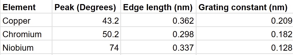
- From the X-ray intensity peaks, the Miller indices indicate a face-centered cubic (FCC) copper matrix (111) and a body-centered cubic (BCC) chromium and niobium phase (110 and 211 hkl family groups)
- Separation into binary alloy is expected of GRCop and is parallel with past studies. This separation is conducive to the alloy’s thermomechanical properties, as the copper matrix is highly thermally conductive; the CrNb BCC laves provides exceptional mechanical stability
- Nanocrystalline grain sizes further increase the yield strength of the alloy, as directly stated by the Hall-Petch effect. Grain sizes are still large enough to prevent the inverse Hall-Petch phenomenon. Void swelling suppression is enhanced
- Grain size only increased by 15% after heat treatment, which is very promising for maintaining NC stability, something integral for material integrity
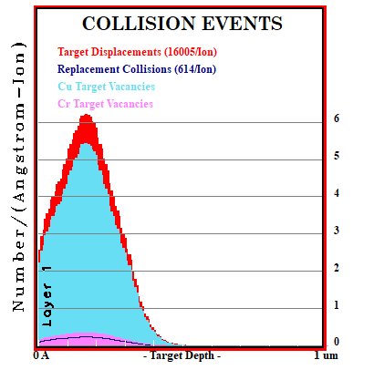
The following is the data for GRCop 84 from SRIM. Most values for GRCop 84 and 42 are the same from SRIM:
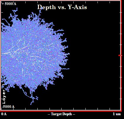
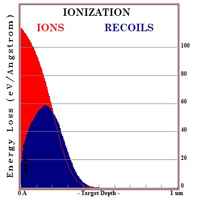
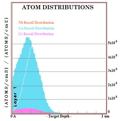
- The simulated thermal neutron penetration depth is only 0.5 μm, relatively small and not as detrimental for its mechanical properties. Penetration depth will likely increase as the displacements per atom (dpa) increases.
- Phonon distribution is most concentrated at 0.25 μm. This may cause phonon-phonon interference, which causes a reduction in the thermal conductivity of the material.
- High ionizations at the surface of the material also decrease conductivity
- As expected, the Cr2Nb laves are absorbing a significant amount of energy
- Overall, the thermophysical and mechanical properties of GRCop will not change drastically internally in low dpa environments
- This study’s data is promising for the implementation of GRCop in fission reactors, however, more research needs to be conducted to evaluate its full potential
Limitations:
- Bragg’s and Scherrer’s equation assumes that peak broadening is only due to grain growth. However, this may neglect other factors such as background noise.
- Grain size and grating constant values were calculated by hand, which increases its inaccuracy. The software originally used, GSAS II, was faulty.
- There was a lack of grants to access billion-dollar facilities to irradiate the sample.
- Because of the powder form of the alloy, we were unable to gather specific yield strength and modulus values.
Future Directions:
- Cold spray the GRCop 84 and 42 samples to conduct hardness and strength tests
- Conduct multiple trials of this experiment to ensure its repeatability
- Incorporate GRCop into current/new fission/fusion reactors for extended periods of time to determine its real-world applicability
- Use a crystal plasticity model to better predict the coalescence and growth of dislocations and voids
- Research the behaviors of tungsten, a highly promising material, in fission reactors
Conclusion
- In this study, we tested the properties of Glenn Research Copper to assess its suitability in fission reactors
- GRCop’s nanocrystalline structure with high grain stability allows for it to maintain its enhanced strength, as stated by the Hall-Petch effect
- However, high phonon distributions and ionization at the surface of the material could greatly hinder its thermal conductivity
- Results from this study support its implementation into nuclear reactors, but more research is needed.
Citations
[1] “2024 world nuclear report,” World Nuclear Association, Aug. 2024. Accessed: Sep. 25, 2025. [Online]. Available: https://world-nuclear.org/images/articles/World-Nuclear-Performance-Report-2024.pdf [2] G. H. Marcus, “Considering the next generation of nuclear power plants,” Prog. Nuclear Energy, vol. 37, no. 1–4, pp. 5–10, Jan. 2000, doi: 10.1016/s0149-1970(00)00016-0. [3] P. Bórawski, A. Bełdycka-Bórawska, B. Klepacki, L. Holden, T. Rokicki, and A. Parzonko, “Changes in gross nuclear electricity production in the European Union,” Energies, vol. 17, no. 14, p. 3554, Jul. 2024, doi: 10.3390/en17143554. [4] S. J. Zinkle and G. S. Was, “Materials challenges in nuclear energy,” Acta Mater., vol. 61, no. 3, pp. 735–758, Feb. 2013, doi: 10.1016/j.actamat.2012.11.004. [5] “Levelized Cost of New Generation Resources in the Annual Energy Outlook 2022,” US Energy Information Administration, Mar. 2022, [Online]. Available: https://www.eia.gov/outlooks/aeo/pdf/electricity_generation.pdf [6] “Methodologies for Assessing the Economic Consequences of Nuclear Reactor Accidents,” Nuclear Energy Agency. Accessed: Oct. 08, 2025. [Online]. Available: https://www.oecd-nea.org/upload/docs/application/pdf/2019-12/2228-methodologies-assessing.pdf [7] S. Ion, “Challenges to deployment of twenty-first century nuclear reactor systems,” Proc. Math. Phys. Eng. Sci., vol. 473, no. 2198, p. 20160815, Feb. 2017, doi: 10.1098/rspa.2016.0815. [8] G. S. Was, D. Petti, S. Ukai, and S. Zinkle, “Materials for future nuclear energy systems,” J. Nucl. Mater., vol. 527, no. 151837, p. 151837, Dec. 2019, doi: 10.1016/j.jnucmat.2019.151837. [9] “Light Water Reactor Sustainability Program,” Janurary 2012. [Online]. Available: https://www.energy.gov/sites/prod/files/INL-EXT-11-23452_LWRS_Program_Plan.pdf [10] S. J. Zinkle, “Opportunities and challenges for materials innovation in nuclear energy,” EPJ Web Conf., vol. 51, p. 01001, 2013, doi: 10.1051/epjconf/20135101001. [11] E10 Committee, “Practice for neutron radiation damage simulation by charged-particle irradiation,” ASTM International, West Conshohocken, PA, 2015. doi: 10.1520/e0521-96r09e02. [12] G. S. Was, Y. Ashida, and P. L. Andresen, “Irradiation-assisted stress corrosion cracking,” Corros. Rev., vol. 29, no. 1–2, pp. 7–49, Sep. 2011, doi: 10.1515/corrrev.2011.020. [13] D. Feron, Nuclear Corrosion Science and Engineering. Woodhead Publishing, 2012. [Online]. Available: https://scispace.com/pdf/nuclear-corrosion-science-and-engineering-1us24pqlca.pdf [14] F. A. Garner, M. B. Toloczko, and B. H. Sencer, “Comparison of swelling and irradiation creep behavior of fcc-austenitic and bcc-ferritic/martensitic alloys at high neutron exposure,” J. Nucl. Mater., vol. 276, no. 1–3, pp. 123–142, Jan. 2000, doi: 10.1016/s0022-3115(99)00225-1. [15] Gary Was, Fundamentals of radiation materials science: Metals and alloys, 2007th ed. Berlin, Germany: Springer, 2007. doi: 10.1007/978-3-540-49472-0. [16] S. J. Zinkle and J. Steven, “Radiation-Induced Effects on Microstructure,” in Comprehensive Nuclear Materials, vol. 1, Unknown, 2012, pp. 65–98. [Online]. Available: http://dx.doi.org/ [17] J. Fu et al., “Modelling the effects of void swelling and spatial heterogeneity on the fracture of metallic materials by crystal plasticity,” Proc. Math. Phys. Eng. Sci., vol. 480, no. 2296, Aug. 2024, doi: 10.1098/rspa.2024.0028. [18] M. Lee, G. Kim, and S. Ahn, “Swelling at high radiation damage levels of 120 and 240 dpa in 3.5 MeV self-ion irradiated ferritic/martensitic steels,” Nucl. Eng. Technol., vol. 56, no. 10, pp. 4115–4126, Oct. 2024, doi: 10.1016/j.net.2024.05.014. [19] C. Du et al., “Ultrastrong nanocrystalline steel with exceptional thermal stability and radiation tolerance,” Nat. Commun., vol. 9, no. 1, p. 5389, Dec. 2018, doi: 10.1038/s41467-018-07712-x. [20] S. Srinivasan et al., “Radiation tolerance and microstructural changes of nanocrystalline Cu-Ta alloy to high dose self-ion irradiation,” Acta Mater., vol. 195, pp. 621–630, Aug. 2020, doi: 10.1016/j.actamat.2020.05.061. [21] M. A. Adaan-Nyiak et al., “Design and development of stable nanocrystalline high-entropy alloy: Coupling self-stabilization and solute grain boundary segregation effects,” Small, vol. 20, no. 27, p. e2309631, Jul. 2024, doi: 10.1002/smll.202309631. [22] M. A. Adaan-Nyiak, I. Alam, G. A. Arcuri, and A. A. Tiamiyu, “Design of self-stable nanocrystalline high-entropy alloy,” Mater. Des., vol. 236, no. 112482, p. 112482, Dec. 2023, doi: 10.1016/j.matdes.2023.112482. [23] J. Gilleland, R. Petroski, and K. Weaver, “The traveling wave reactor: Design and development,” Engineering (Beijing), vol. 2, no. 1, pp. 88–96, Mar. 2016, doi: 10.1016/j.eng.2016.01.024. [24] Y. Guérin, G. Was, and S. Zinkle, “Materials challenges for advanced nuclear energy systems,” MRS Bulletin, vol. 34, pp. 10–19, Jan. 2009, doi: 10.1017/S0883769400100028. [25] A. S. Kuprin et al., “Irradiation resistance of chromium coatings for ATFC in the temperature range 300–550°C,” J. Nucl. Mater., vol. 549, no. 152908, p. 152908, Jun. 2021, doi: 10.1016/j.jnucmat.2021.152908. [26] P. Rodríguez, “Selection of materials for heat exchangers,” IAEA Bull., Apr. 1997, [Online]. Available: https://inis.iaea.org/records/5bzq4-43m09 [27] A. A. Shirzadi and S. Jackson, “Structural Alloys for Power Plants: Operational Challenges and High-Temperature Materials,” pp. 1–494, Jan. 2014, [Online]. Available: https://www.researchgate.net/publication/291088877_Structural_Alloys_for_Power_Plants_Operational_Challenges_and_High-Temperature_Materials [28] “Technical data for the elements in the Periodic Table,” Periodic Table. Accessed: Oct. 03, 2025. [Online]. Available: https://periodictable.com/Elements/050/data.html [29] H. Wang, “Noble Metals,” in Membrane-Based Separations in Metallurgy, Elsevier, 2017, pp. 249–272. doi: 10.1016/b978-0-12-803410-1.00009-8. [30] “Online materials information resource - MatWeb.” Accessed: Dec. 15, 2025. [Online]. Available: https://www.matweb.com/ [31] Y. Chen et al., “Thermophysical properties of additively manufactured (AM) GRCop-42 and GRCop-84,” Mater. Today Commun., vol. 36, no. 106665, p. 106665, Aug. 2023, doi: 10.1016/j.mtcomm.2023.106665. [32] S. A. Fabritsiev, A. S. Pokrovsky, and S. J. Zinkle, “Effect of neutron dose and spectra, He/dpa ratio and Ni and Zn accumulation on irradiation damage of pure copper and PH and DS copper alloys,” Fusion Eng. Des., vol. 38, no. 4, pp. 459–473, Feb. 1998, doi: 10.1016/s0920-3796(98)00106-9. [33] K. R. Anderson and J. R. Groza, “Microstructural size effects in high-strength high-conductivity Cu-Cr-Nb alloys,” Metall. Mater. Trans. A, vol. 32, no. 5, pp. 1211–1224, May 2001, doi: 10.1007/s11661-001-0130-x. [34] A. Mohammadi, S. Hamidi, and M. A. Asadabad, “The use of the SRIM code for calculation of radiation damage induced by neutrons,” Nucl. Instrum. Methods Phys. Res. B, vol. 412, pp. 19–27, Dec. 2017, doi: 10.1016/j.nimb.2017.08.036. [35] M. A. Adaan-Nyiak, I. Alam, and A. A. Tiamiyu, “Ball milling process variables optimization for high-entropy alloy development using design of experiment and genetic algorithm,” Powder Technol., vol. 427, no. 118766, p. 118766, Sep. 2023, doi: 10.1016/j.powtec.2023.118766. [36] S. A. Hassanzadeh-Tabrizi, “Precise calculation of crystallite size of nanomaterials: A review,” J. Alloys Compd., vol. 968, no. 171914, p. 171914, Dec. 2023, doi: 10.1016/j.jallcom.2023.171914. [37] V. S. Vinila and J. Isac, “Synthesis and structural studies of superconducting perovskite GdBa2Ca3Cu4O10.5+δ nanosystems,” in Design, Fabrication, and Characterization of Multifunctional Nanomaterials, Elsevier, 2022, pp. 319–341. doi: 10.1016/b978-0-12-820558-7.00022-4. [38] M. S. Wartak and C.-Y. Fong, “Bragg’s Law,” in Field Guide to Solid State Physics, SPIE, 2019. doi: 10.1117/3.2510243.ch16. [39] R. Lumley, A. Morton, and I. Polmear, “Nanoengineering of metallic materials,” in Nanostructure Control of Materials, Elsevier, 2006, pp. 219–250. doi: 10.1533/9781845691189.219. [40] J. F. Kielkopf, “New approximation to the Voigt function with applications to spectral-line profile analysis,” J. Opt. Soc. Am., vol. 63, no. 8, pp. 987–995, Aug. 1973, doi: 10.1364/JOSA.63.000987. [41] E. E. Whiting, “An empirical approximation to the Voigt profile,” J. Quant. Spectrosc. Radiat. Transf., vol. 8, no. 6, pp. 1379–1384, Jun. 1968, doi: 10.1016/0022-4073(68)90081-2. [42] K. Urban and N. Yoshida, “The threshold energy for atom displacement in irradiated copper studied by high-voltage electron microscopy,” Philos. Mag. A, vol. 44, no. 5, pp. 1193–1212, Nov. 1981, doi: 10.1080/01418618108235802. [43] D.-Y. Lin, H. Song, and X. D. Hui, “Molecular dynamics simulation of threshold displacement energy and primary damage state in Niobium,” arXiv [cond-mat.mtrl-sci], Feb. 12, 2017. [Online]. Available: http://arxiv.org/abs/1702.03598 [44] “The Proton induced Displacement Cross Section: SRIM comparison with DXS,” International Atomic Energy Agency. Accessed: Oct. 09, 2025. [Online]. Available: https://www-nds.iaea.org/CRPdpa/SRIM_vs_DXS.pdf
Acknowledgement
Artificial intelligence assisted in the visualization of the X-ray intensity graphs. It helped me create a python script to plot the values. All other work in this project is authentic and conducted without the assistance of AI.
Additionally, I would like to thank Ben Hewitt, Dr. Ahmed Tiamiyu, and Dr. Beatriz Garcia for their support in this project. They have guided me through many difficulties and has allowed me to achieve success in this project.