Boundary Layer Tripping Methods and Their Effect on the Performance of an Airfoil
Grade 8
Presentation
Hypothesis
Null Hypothesis: If the airfoils are put through an airstream, then there will be no difference in drag if the airfoils have a positive or negative variation because golf balls use negative bumps, and the Bugatti Bolide uses positive bumps.
Hypothesis (Alternative Hypothesis): If the airfoils are put through an airstream, then the airfoils with bumps will perform better than the rest because the company, Bugatti, uses bumps instead of ridges on the roof of their Bugatti Bolide. Since the Bugatti Bolide is the 4th fastest car to exist (according to Luxe Digital), there is lots of work going into the engineering and drag of it.
Hypothesis Conclusion for Best Airfoil: If the airfoils are put through an airstream, then the airfoil with the negative or positive bumps will perform the best because of the same concept in the bugatti bolide and as mentioned in the Null Hypothesis, the difference between negative and positive is predicted to be none.
Overall, the airfoils with variations will all perform better than the control because they generate vortices to reduce drag.
Research
Terms:
- EDF = Electric Ducted Fan.
- Negative vs Positive = Referring to bumps or ridges, negative is protruding into the airfoil and positive is extruding outwards.
- Vortex (plural vortices) = Whirling mass of air.
- Vector = A quantity which has magnitude and direction.
Topics:
1. Stalls
2. Drag
3. Vortex Generators
4. Aerodynamics Behind Golf Balls
Stalls
Stalls are a common concept in aviation. A stall is caused when the boundary layer of the wing gets detached. This is normally caused by too high of an angle of attack. A common misconception about stalls is that they only happen at low speeds. This is untrue and stalls can happen at any speed.
Drag
Drag is the backwards force on all aerodynamic objects. The drag force is measured in Newtons. There are two types of drag on an airplane. There is induced drag, and parasitic drag. Induced drag is the drag created when making lift. If the wing has any positive degree of angle of attack, there will be induced drag associated with the lift because the lift vector is slightly backwards. Parasite drag is the drag produced from an object "dragging" through the air. For example, when you stick your hand out the window of a car, it gets pushed backwards. "It makes no difference whether the object moves through a static fluid or whether the fluid moves past a static solid object" (NASA Glenn Research Center [see Citations]).
Vortex Generators
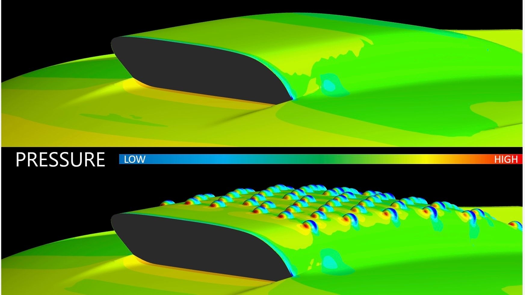
Vortex generators are aerodynamic devices that reduce stall speed and drag on aircrafts and high-performance automobiles. As the name suggests, they create vortices to increase performance. On an airfoil, the boundary layer is a low energy area, whereas the free-stream airflow is a high energy area. The vortex generators create mini wingtip vortices which extend from the boundary layer to the free-stream airflow. This adds energy to the usually low energy area which keeps the boundary layer more attached and also reduces drag.
Aerodynamics Behind Golf Balls
A commonly overlooked feature of the golf ball is its dimples. No, they are not just for looks, the dimples act the same way as the vortex generators mentioned before. They add energy to the boundary layer of the golf ball so it doesn't detach as early. This helps prevent a large vortex which a smooth golf ball would have. Even though the drag on the surface of the golf ball is more than a smooth one, it accounts for the drag from pressure behind the golf ball. Did you know, a smooth golf ball would only fly half the distance a dimpled one would? This fact shows the true importance of these tiny marvels of aerodynamics. Also, the company, Bugatti, used this concept on golf ball concept on the roof of their Bugatti Bolide.
Variables
Manipulated Variable: Variations to airfoils to trip the boundary layer (ex. positive bumps, negative ridge etc.).
Responding Variable: Drag of airfoils (N).
Controlled Variables: Size of airfoils, airfoil shape before the variations, speed of airflow, amount of air in airflow, weight of airfoils, distance from EDF, type of EDF, angle of airfoils, position of newton meter mount to airfoil, angle of airfoil to Newton meter, battery in EDF, percentage of battery in EDF, temperature of air, temperature of EDF, temperature of airfoils, position of variation.
Procedure
-
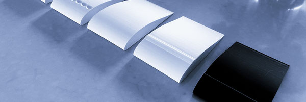
3D print airfoils using 15% infill and 4 outer layers.
-
Drill a small hole perpendicular to the airfoil, 4 cm from the left side (bottom up), and 10 cm from the trailing edge.
-
Screw the Newton Meter L-shaped attachment into the airfoil.
-
Make sure the airfoil is exactly parallel to the Newton meter using a ruler.
-
Charge the RC battery.
-
Set newton meter to 0.5 Newtons of downwards force.
-
Align the airfoil 10 cm away from the EDF.
-
Turn off engine safety and initiate full power.
-
Record data.
-
Follow steps 5-7.
-
Align the airfoil 15 cm away from the EDF.
-
Turn off engine safety and initiate full power.
-
Record data.
-
Repeat for more trails/other airfoils.
Observations
This experiment was solely based on quantitative observations.
In first experiment, I realised I had made the negative and positive bumps too far forward and they weren't in the same position as the ridges. This was a source of error and I discarded my results. I redesigned the bumps so they were in the same position as the ridge to insure a controlled experiment. I then retested and got the following results.
Results:
| Variation to Airfoil | Drag Force (N) | |||
| 10 cm from EDF | 15 cm from EDF | |||
| Trial 1 | Trial 2 | Trial 3 | Trial 4 | |
| Control | 0.25 | 0.26 | 0.16 | 0.18 |
| Positive Ridge | 0.22 | 0.21 | 0.17 | 0.17 |
| Positive Bumps | 0.25 | 0.26 | 0.22 | 0.23 |
| Negative Ridge | 0.24 | 0.22 | 0.18 | 0.17 |
| Negative Bumps | 0.29 | 0.29 | 0.25 | 0.26 |
I noticed that trials 1 and 2 (10 cm from EDF) and 3 and 4 (15 cm from EDF) had different results. I expected different values, but the order of airfoils from least drag to most drag completely changed.
Analysis
*For all airfoils, trials 3 and 4 were done 15 cm away from the EDF whereas trials 1 and 2 were done 10 cm away.

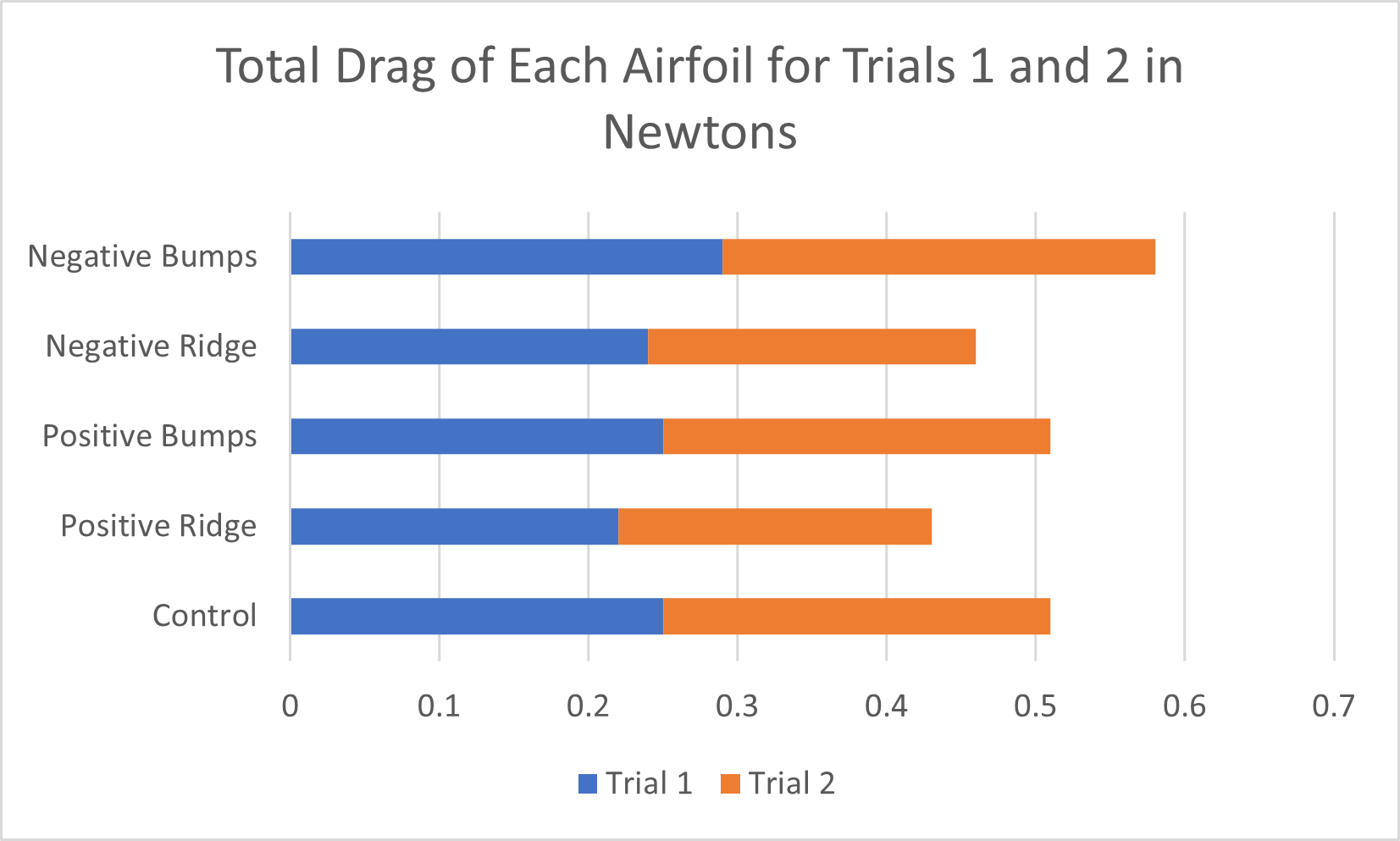
This is the first of many graphs. This graph shows the total drag of all the trials combined for each airfoil. It makes it easy to see which airfoil did the best and by how much. Each colour represents a trial, as shown in the legend.
The order from best to worst total is:
- Positive Ridge
- Negative Ridge
- Control
- Positive Bumps
- Negative Bumps
The Positive Ridge performed the best in total and performed 9.4% better than the control.
Of course, the total alone doesn't tell you everything. Let's compare the data from trial 1 and 2 with trial 3 and 4.
Trials 1 and 2 are done 10 cm away from the EDF. Trials 3 and 4 are done 15 cm away from the EDF. Here is the airfoils' data:
| Variation to Airfoil | Drag Force (N) | |||
| 10 cm from EDF | 15 cm from EDF | |||
| Trial 1 | Trial 2 | Trial 3 | Trial 4 | |
| Control | 0.25 | 0.26 | 0.16 | 0.18 |
| Positive Ridge | 0.22 | 0.21 | 0.17 | 0.17 |
| Positive Bumps | 0.25 | 0.26 | 0.22 | 0.23 |
| Negative Ridge | 0.24 | 0.22 | 0.18 | 0.17 |
| Negative Bumps | 0.29 | 0.29 | 0.25 | 0.26 |
As you can see, the drag force is significantly less in trials 3 and 4. This was expected because the airflow from the EDF loses energy over distance, and it is also no longer in the fan duct. What's interesting though, is when you compare the airfoils together.
Take a look below at the comparison between the Control and the Positive Bumps below:
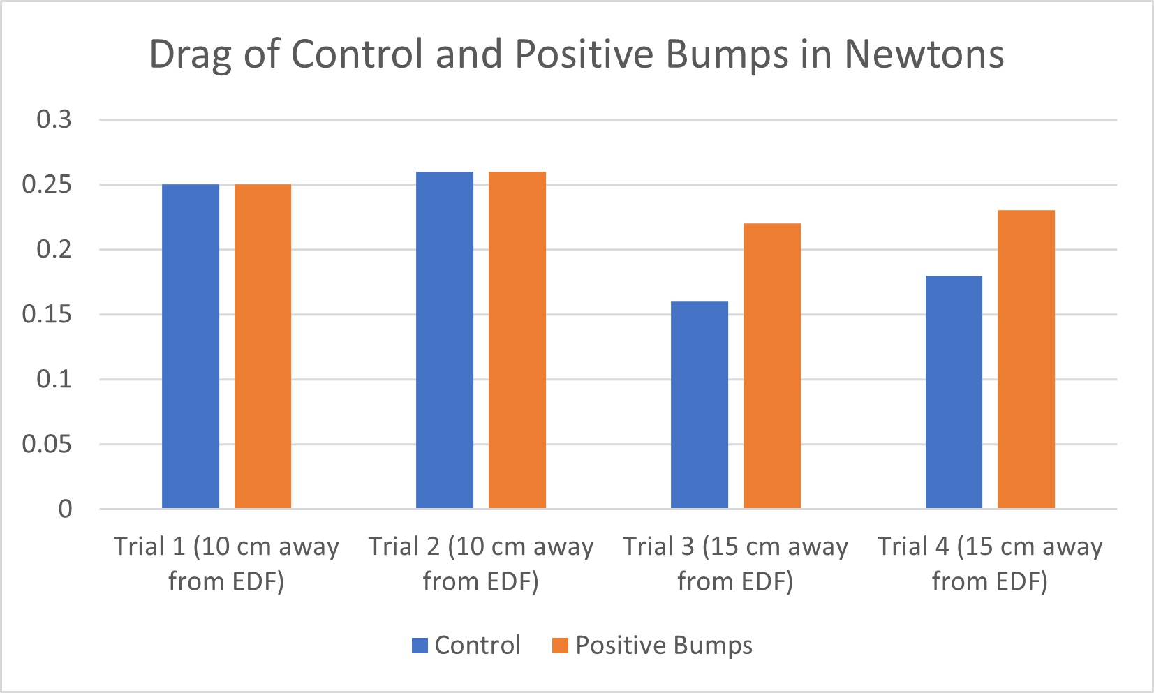
The drag from 10 cm away is equal with both airfoils, but when the airfoils are moved back to 15 cm, the control performs better. Why is that so? What's happening is on the Positive Bumps, the bumps are creating drag, but the vortices and turbulence are making up for that drag. This is why the values are equal to the control. When you slow down, less vortices and turbulence are created so they are no longer making up for the drag created with the bumps. Therefore, the control, which has no bumps, out performs the Positive Bumps at low speeds. This is also why the Bugatti Bolide's roof has dimples that only extrude at high speeds. It is because they are not as efficient as a smooth surface at low speeds.
The graph below further illustrates this data. It is the total drag from trials 3 and 4.
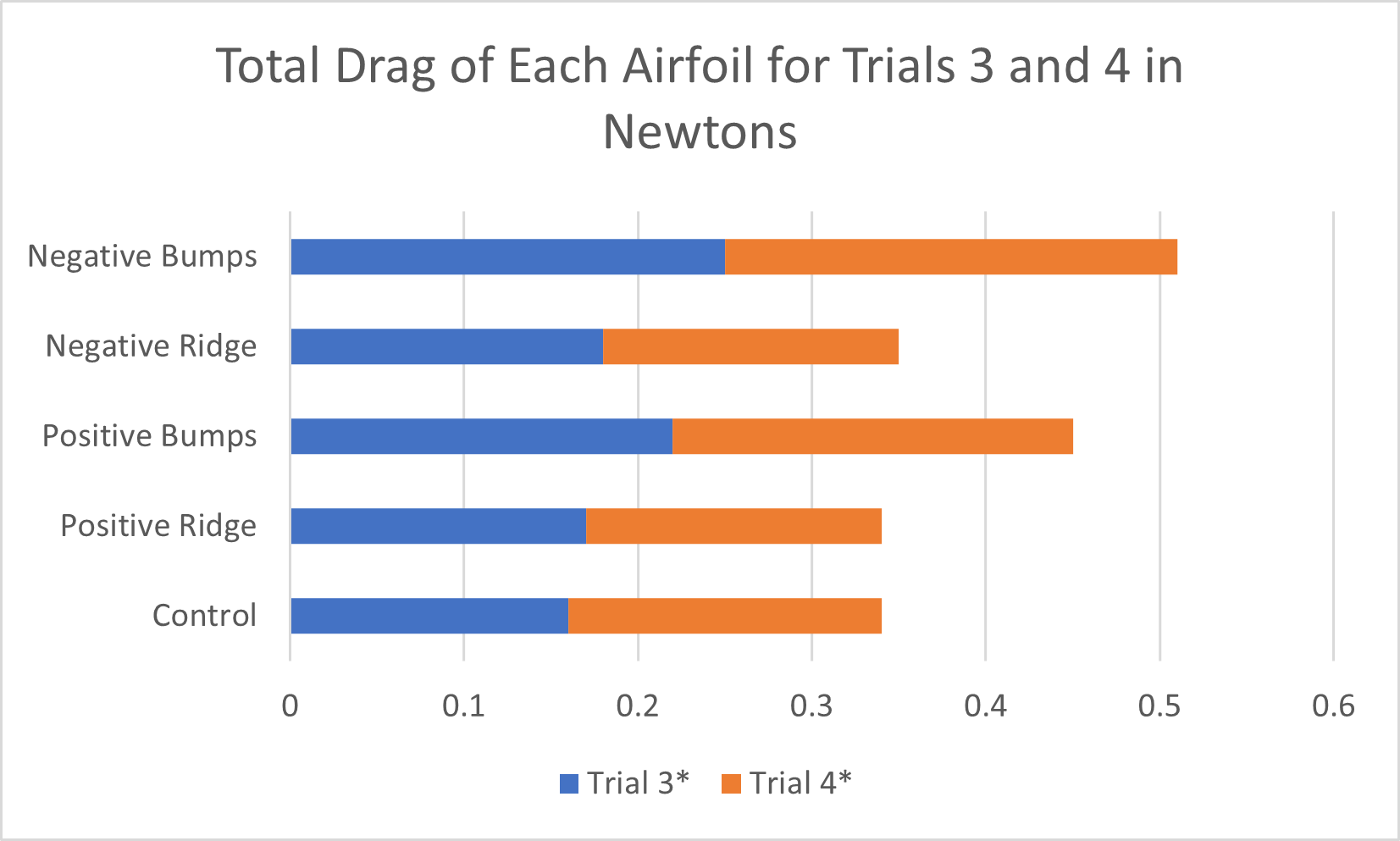
As you can see, the Control and the Positive Ridge have the least drag, and no airfoil performed better than the control.
If we compare the airfoils in trials 1 and 2, we see different results.
As you can see, two airfoils performed better than the Control in terms of drag and one airfoil performed the same as the Control. This is an improvement from trials 3 and 4, where no airfoils had less drag than the control. In these trials, the Positive Ridge performed 15.7% better than the Control. Let's now look at the differences between negative variations and positive variations.
As shown in the legend, the blue represents positive, and the orange represents negative. You can clearly see that the Positives variations produce less drag than the Negatives. I have a theory on why that is. If you compare where the vortex creation happens, you'll notice that the positive variations create vortices slightly higher than the negatives.
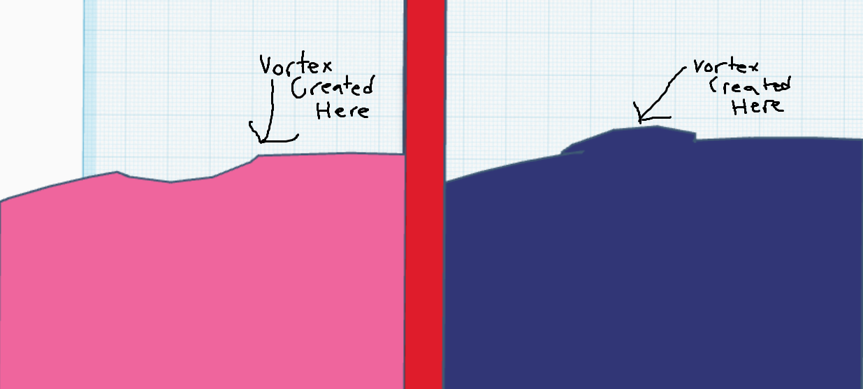
This means that the vortices on the negative variation won't extend into the free-stream airflow as much, meaning they won't add as much energy to the boundary layer.
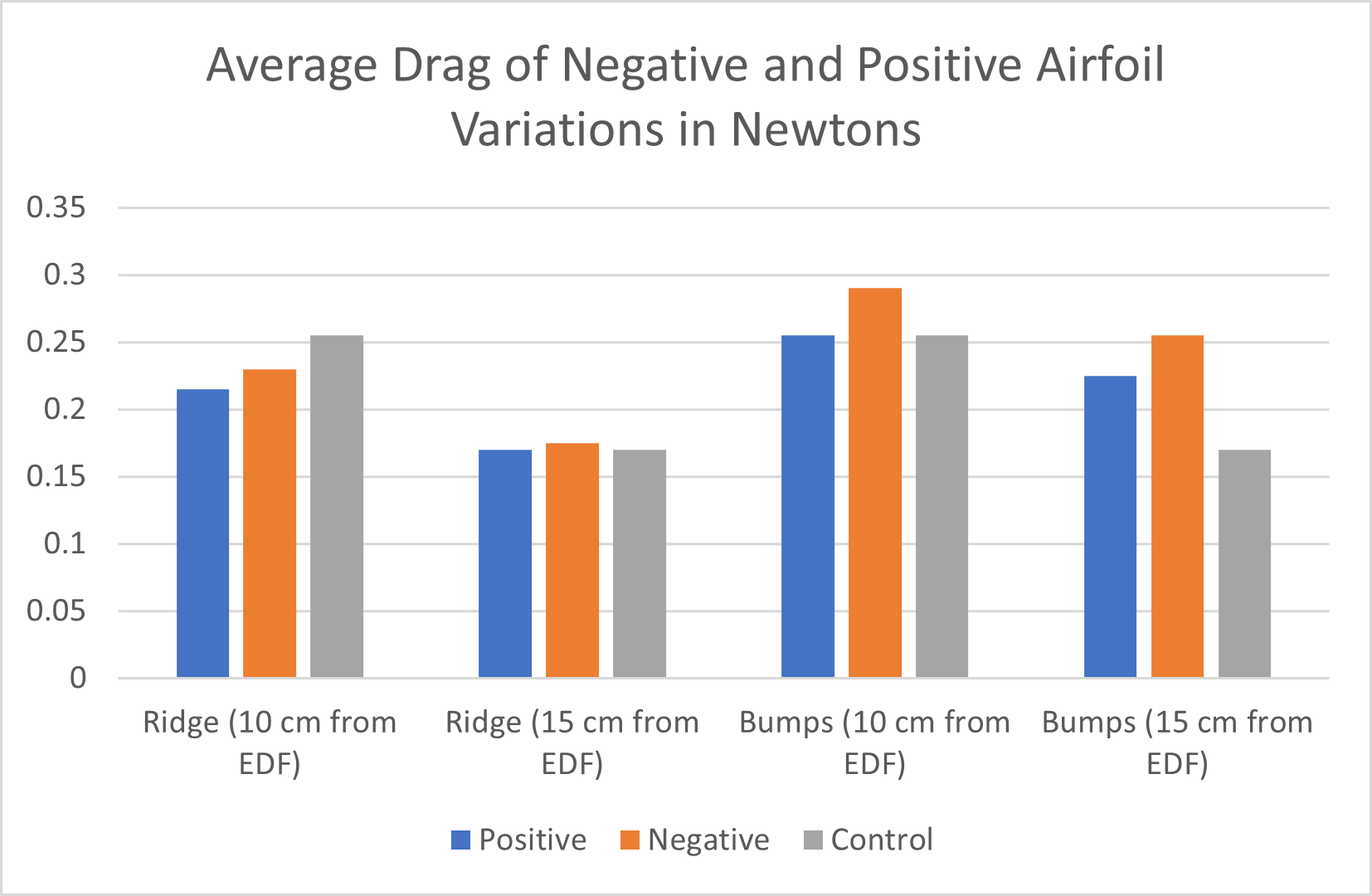
Now let's compare bumps and ridges.

The ridges performed much better than the bumps. I believe this is because the bumps aren't creating the same vortices as the ridges, so the drag isn't getting reduced. I talked with two experts about this (see acknowledgements). They both weren't quite sure, but they thought it had something to do with the behavior of the vortices. The bumps were either not creating the vortices, or they vortices were interfering with each other. They both suggested to do tests where the position and size of the bumps were changed in the future.
Conclusion
In conclusion, the airfoil variation that performed the best (in terms of drag) was the Positive Ridge. It performed 9.4% better than the Control in total, and from 10 cm away, it performed 15.7% better. This was because of its higher vortex generation point allowing it to bring more energy into the boundary layer. Overall, positive variations performed better than negative variation, and ridges performed better than bumps. Unfortunately, my multiple hypotheses were all wrong. I thought that negative and positive variations would have no difference in drag, but I didn't account for the difference in vortex generation point. I also assumed that bumps would perform better than ridges because of real world evidence. I was proven wrong again and ridges performed better than bumps, most likely because of the vortex behavior. Lastly, I thought that all the modified airfoils would perform better than the control, and I was proven wrong once again. This experiment displays the unpredictable and counterintuitive world of aeronautics.
If I were to do this experiment again, I would test different positions and sizes of the airfoil variations. I would also do more trials and would also investigate how these variations would affect stall speed and lift.
Application
The concepts and results of my experiments can be applied to many things. Airlines and aircraft manufacturers can benefit by using these concepts. This is because they will have less drag which will save fuel, money, and help the environment. This concept would be especially useful to gliders, which require as little drag as possible so they can stay up in the air. I can benefit from this experiment too. I enjoy flying remote control aircraft. The only problem is that I can only fly them for around 10 minutes before I have to charge them. By incorporating these aerodynamic improvements to the wings, I will be able to fly for longer.
Sources Of Error
Though I try to control as much as I can, there are still going to be sources of error. Some sources of error that could've affected my results were:
- Accuracy of 3D printer. The 3D printer sometimes makes small mistakes (for example, it might print a layer 0.1 millimeters bigger than another). This could affect drag.
- Drafts around my room. Though my door was closed, there are still drafts that could affect the airflow and drag.
- Trials. Sometimes anomalies occur. If I did more trials, (ex. 100) the anomalies that occur would have minimal effect.
Citations
References
Edelstein, S. (2021, January 1). The Bugatti Bolide’s air scoop was designed like a golf ball. Motor Authority. https://www.motorauthority.com/news/1130680_the-bugatti-bolide-s-air-scoop-was-designed-like-a-golf-ball
How do dimples in golf balls affect their flight? (n.d.). Scientific American. Retrieved March 17, 2025, from https://www.scientificamerican.com/article/how-do-dimples-in-golf-ba/
Pilot Institute. (2025, January 8). What is a stall? - when wings stop working. Pilot Institute. https://pilotinstitute.com/what-is-a-stall/
Vortex generators: Preventing stalls at high and low speeds. (n.d.). Boldmethod.com. Retrieved March 17, 2025, from https://www.boldmethod.com/learn-to-fly/aerodynamics/vortex-generators/
What am I? Vortex generators. (2017, January 8). Aopa.org. https://www.aopa.org/news-and-media/all-news/2017/august/flight-training-magazine/vortex-generators
What is Drag? (2021, July 15). Glenn Research Center | NASA; NASA Glenn Research Center. https://www1.grc.nasa.gov/beginners-guide-to-aeronautics/what-is-drag/
Luxe Digital. (2024a, February 19). Blink and you’ll miss them: The 11 fastest cars in the world. Luxe Digital. https://luxe.digital/lifestyle/garage/fastest-cars/
Acknowledgement
Thank you to my scientific supervisor, Dr. Sumner, my aeronautic experts, Dr. Eric Doran and Nicholas Hall, and my parents for their financial support and encouragement.