Soaring with the Birds: Using Biomimicry to Improve The Wings of Commercial, Recreational and Rescue Aircraft
Sylvan Zheng
Grade 8
Presentation
Problem
Birds have often been admired for their surprising agility and fluidity in flight, and even with current technologies, we still haven’t mastered flight to their extent. My project aims to bring us one step closer, by tapping into the result of 60 million years of evolution that are bird wings. By replicating features that are found on the wings of birds with flight patterns that today’s aircraft require, I hope that I can further improve wings for use in commercial, recreational and rescue aircraft.
In my project, I tested various bird adaptations on small 3-D printed models of modified traditional aircraft wings in my homebuilt small wind tunnel.
Method
Table Of Contents
Background Research
How does bird flight differ from aircraft flight?
Due to evolutionary pressures and distinct uses, flight in birds has developed differently than in aircraft. Below are some important differences between bird and aircraft flight.
Lift Distribution
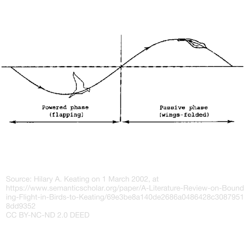
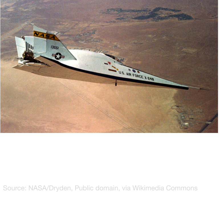
Unlike in most aircraft, birds not only use their wings to fly, but also use their aerodynamic bodies and tails to generate extra lift. If a human-made aircraft had a tail that generated constant lift, it would be very unstable, and the way birds can mitigate this will be discussed in the next section. Some small birds, such as zebra finches, take body lift to the extreme with flap-bounding flight, where the bird alternates between flapping, and just using body lift. This allows these smaller birds to fly at high speeds more efficiently. Humans have tried to adapt the concept of using the fuselage as a wing with lifting body aircraft, which are useful as reentry vehicles in aerospace, but this technology hasn’t yet become applicable on the market because the design suffers at low speeds.
Stabilization
To maintain yaw stability, conventional aircraft have a vertical stabilizer, but birds only have a horizontal stabilizer. To remedy this, birbs actively correct themselves in flight. This also solves the issue of instability with a lift-producing horizontal stabilizer. This feat could not be achieved with a normal centralized nervous system. Even with larger brain-to-body ratios than most animals, expansions of the spinal cord still needed where nerves from the wings are connected allow birds to quickly adjust themselves in flight without needing to wait for the signal to reach the brain, in the same way that we instinctually pull away when we get burned.
Environmental Limitations
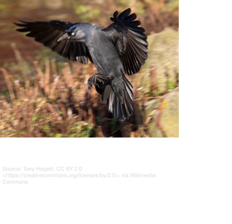
Most aircraft need a sufficiently long runway to be able to take off, but most birds don’t have that luxury. Instead, they usually use the combination of a hop and “Upwards Drag” from a downstroke of their wings to take off, then land at a very high angle of attack using their alulea. Some waterfowl have access to long lake “Runways” that they can run on before takeoff, and lost the ability of immediate takeoff in favour of more aerodynamic, lower lift high-speed wings, which are suitable for long migrations flying over land. This much better matches today’s aircraft, and could act as a stepping stone to biomimic birds.
Propulsion
Traditional aircraft usually use a separate propulsion system, but birds need to use their wings to produce both thrust and lift. This required many adaptations in birds, including wing permeability, because of individual feathers, and larger wing range-of-motion. This allows birds to create thrust and lift on the downstroke, and reduce downforce on the upstroke. Some larger birds, such as birds of prey and seabirds use alternate methods of propulsion that better fit with traditional aircraft, and will be described in the next section.

How have birds adapted for their individual lifestyles, and which ones are most similar to today’s aircraft?
Over 60 million years of evolution, flying birds have diversified in lifestyle and habitat, and evolved four main wing types, each suited for the species' lifestyle and habitat
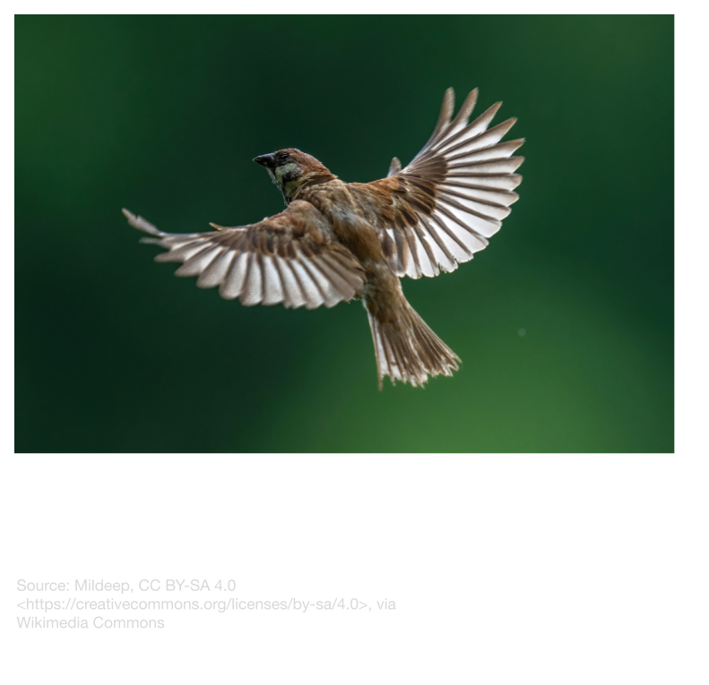
Elliptical Wings
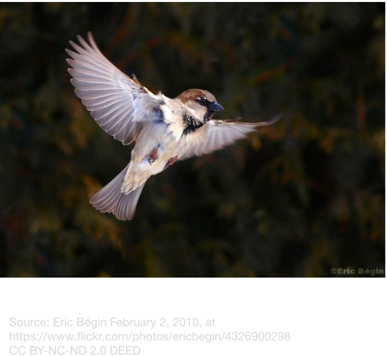
Elliptical wings are highly maneuverable, create a high amount of lift at sufficient speeds, and are suitable for short bursts of high speed. These wing shapes typically belong to forest birds that need to maneuver through tight gaps in the foliage. Smaller birds with elliptical wings also use bounding flight to achieve higher speeds, by tucking in their wings and using body lift. Some examples of birds with elliptical wings are sparrows, crows, magpies, and chickadees. The Supermarine Spitfire used a similar wing shape, but this made it very difficult to manufacture.
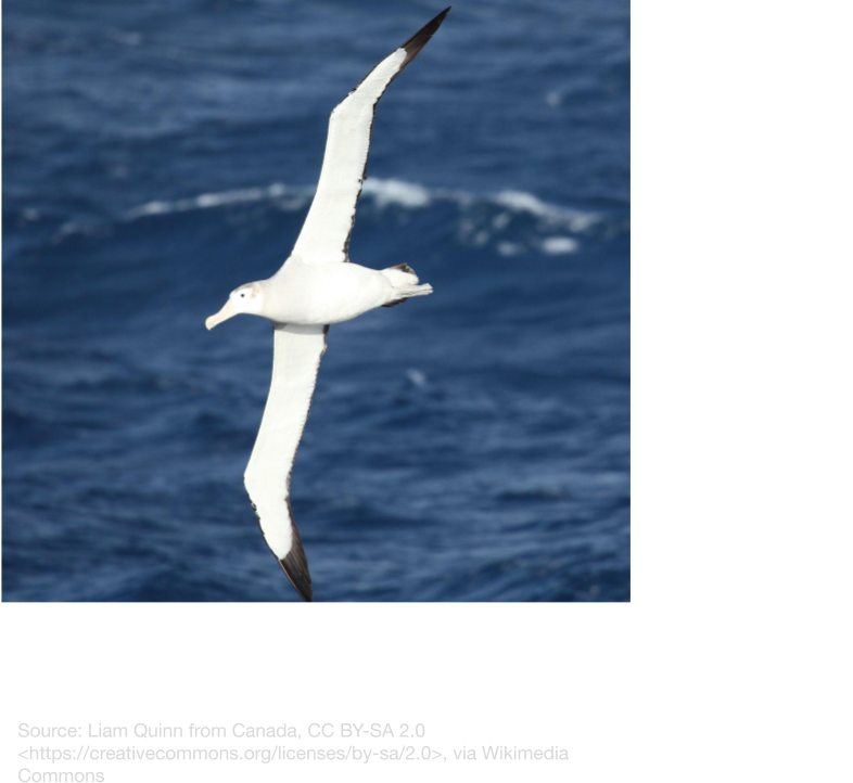
High Aspect Ratio Wings
High aspect ratio wings are often used for active gliding by catching updrafts from wind deflected by waves. The best example is the wandering albatross, one of the most efficient animals in the world. After taking off, the albatross can stay aloft by flying close to the water’s surface and catching updrafts, with only a few flaps of its wings. MIT has taken inspiration from this kind of wing, and proven its feasibility with an unmanned, albatross-inspired combination of a glider and a sailboat. While high aspect ratio wings are efficient for small UAVs, they might not be applicable for heavier aircraft, because of the weight constraints of this design.
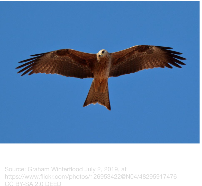
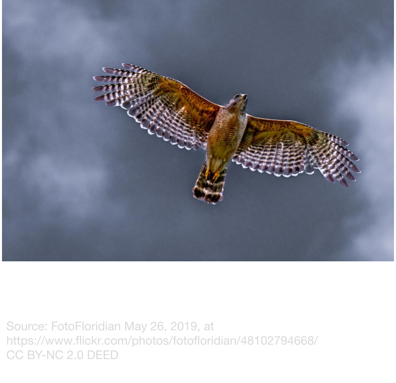
Slotted High-Lift Wings
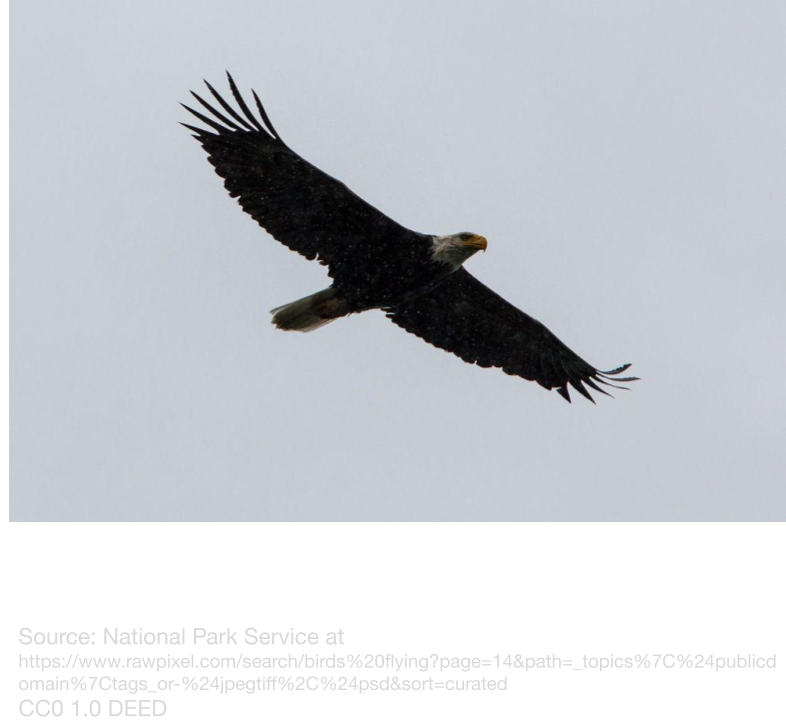
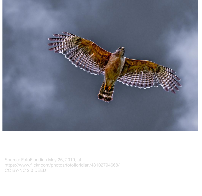
Slotted high-lift wings are often used for slow, passive gliding, and are often found on large birds of prey, such as eagles, hawks and kites. Slotted high-lift wings are deeply cambered, and are slotted at the tips to reduce drag at low speeds. These wings are useful for gliding at slow speeds or catching updrafts, without using much energy. These characteristics make slotted high-lift wings suitable for light gliders, or bush planes that need to produce lift at low speeds.
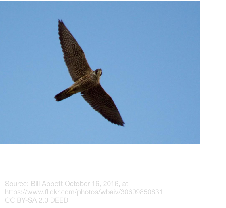
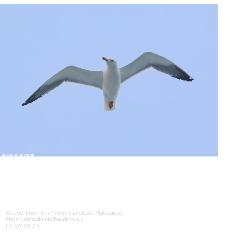
High-Speed Wings
High-speed wings are swept and are designed to reduce drag and still produce lift at high speeds. These wings are swept and taper to a point, to lower camber and prevent air separation at high speeds, much like fighter jets or commercial airliners. These wings are often found on
migratory birds, falcons, and insectivores that need to move quickly. These wings are the most similar to modern-day wings, but many backswept-wing aircraft suffer from wingtip stall first, which could be solved with the forward sweep of the secondary wings of birds.
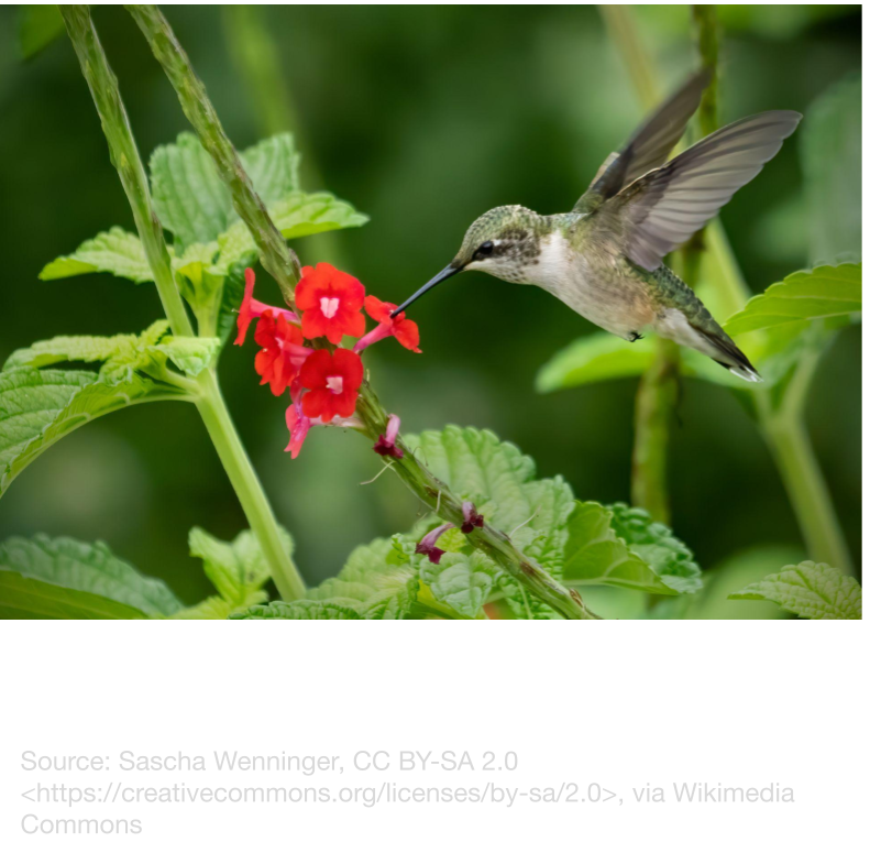
Hovering Wings
Hovering wings are found on small, fast hummingbirds, and can create lift at all times, even when stationary. They achieve this with small wings that are flapping around 70 times per second in a figure-8 movement. This is necessary for hummingbirds because of their diet of hard-to-access nectar. Many attempts have been made to replicate this motion, but the high energy needed might make this design hard to use for aircraft.
Overall, I chose to test aspects of slotted high-lift and high-speed wings, because they best fit the requirements of commercial, recreational and rescue aircraft.

What problems do today’s wings face, how have we countered them, and what bird adaptations could help?
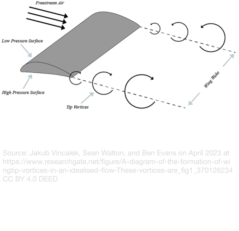
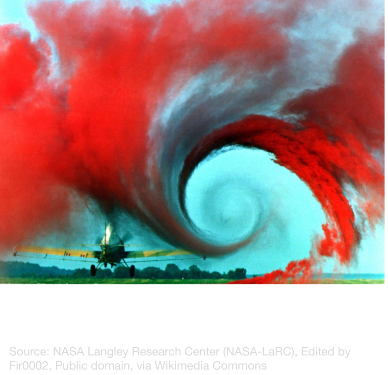
Wing Tip Vortices
The Problem
One way the wing generates lift is by causing a pressure difference between the top and bottom of the wing, by both Bernoulli's principle and the wing’s angle of attack. The high pressure below the wing pushes the wing up into the low-pressure zone in an attempt to equalize the pressure, which can be harnessed as lift. This works on most of the wing, but near the wingtips, the path of least resistance is to flow spanwise, which is parallel to the wing, and around the wingtip to equalize. This renders the wingtips “Ineffective”, as the pressure differential isn’t creating any lift. In addition, this flow also produces drag and spins the air behind it, forming vortices that expand as they move further from the aircraft. This effect decreases as the speed increases, as the air spends less time separated by the wing.
How Current Aircraft Have Countered This
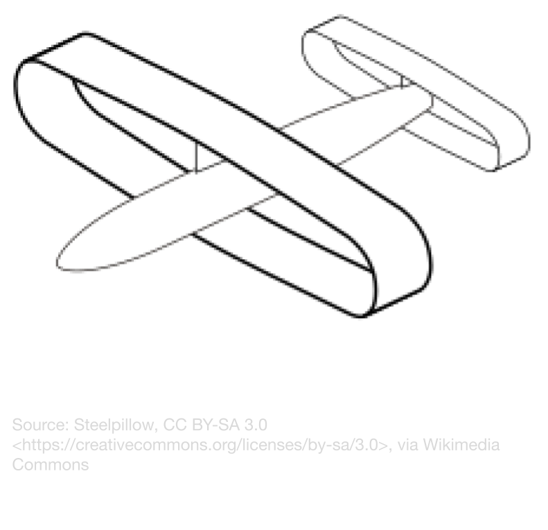
People have recognized this problem and have tried to solve it, usually by strategically adding extra wing area. For example, winglets are small wings added to the wingtips and are usually curved upwards. These provide an extra barrier for air trying to flow around the wingtip, as it has to flow around the wingtips before it reaches the low-pressure zone on top of the wing. Another solution is the addition of wing fences, which are vertical surfaces on the wing that limit the spanwise flow that is required for air to reach the wingtips. Some newer solutions aim to eliminate the wingtips entirely, by making the wing a continuous loop around the fuselage. This is called a closed wing, and can either wrap around the whole aircraft or just the wing tips. This design also comes with the added benefit of being able to fit more wing in the same space. Even with these advantages, closed-wing aircraft still have to solve many issues before they can be widely accepted.
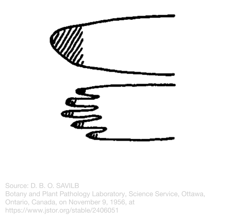
Bird Adaptations That Could Help
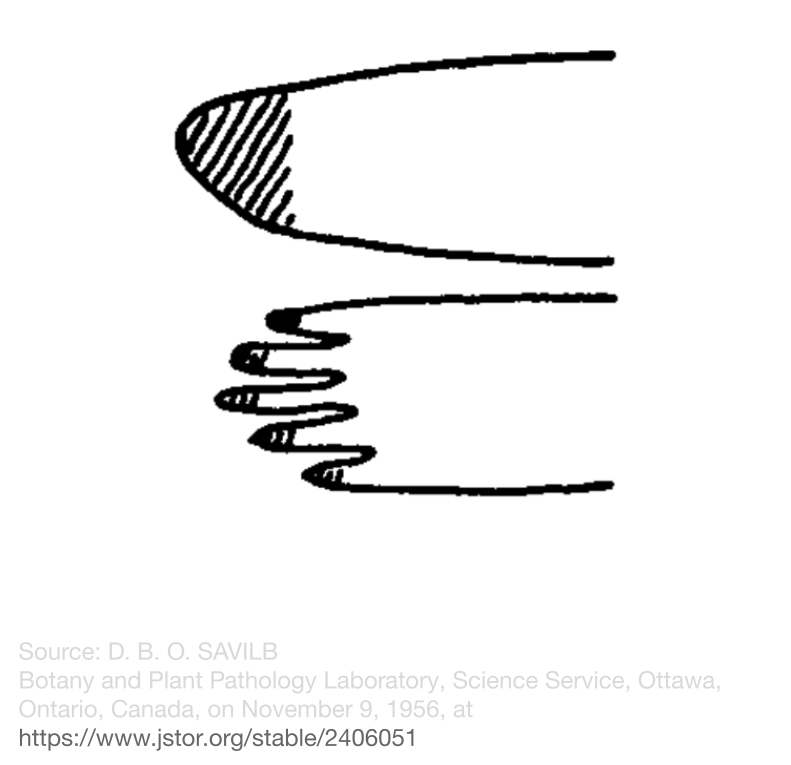
Large birds of Prey glide slowly and passively, so drag caused by wing vortices is a large problem. Their low speed gives the air a lot of time to move toward the wingtips and form vortices, and they can’t get that energy back because of their gliding flight style. To counter this, they have notched wingtips to reduce the wingtip area where vortices form. This reduces the “Ineffective” area of the wing, which both increases lift and reduces drag. Slow-flying aircraft, such as gliders or bush planes, could benefit from this kind of wing, as they have similar limitations as birds of prey.
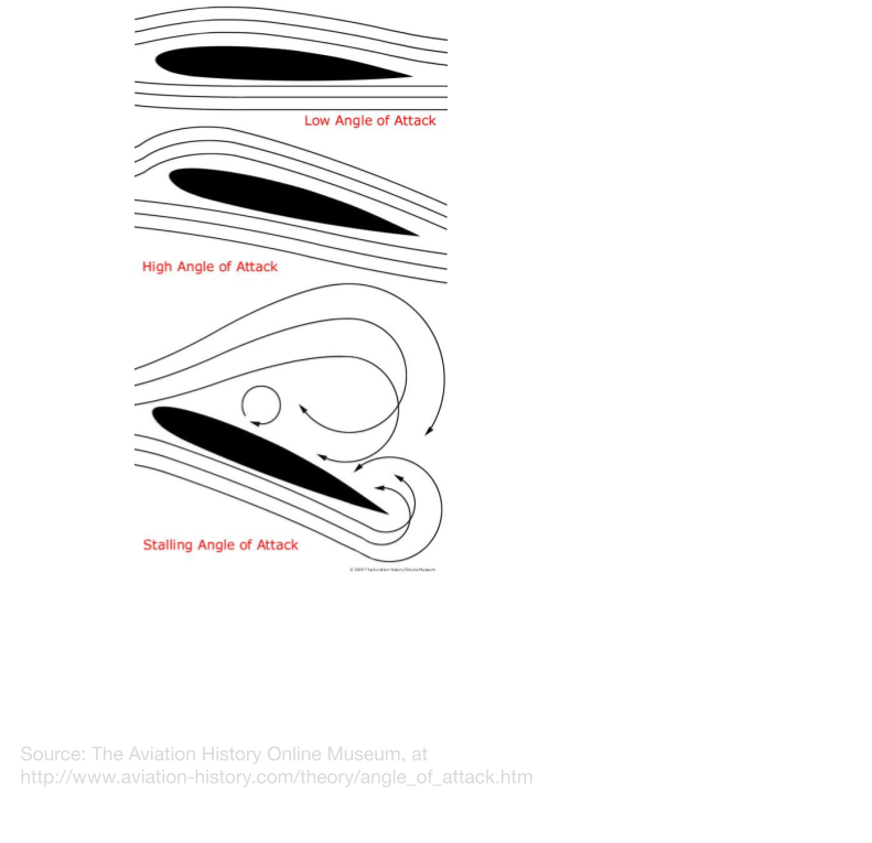
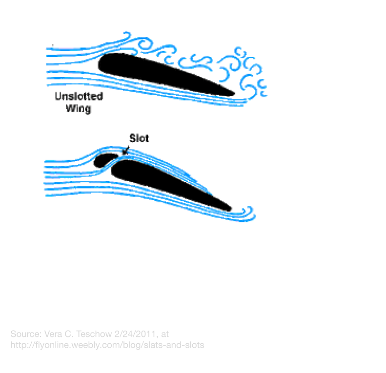
Airflow Separation
The Problem
Another way an airfoil generates lift is by pushing air downwards, and by Newton’s third law, this exerts an upward force on the airfoil. The airfoil does this in two ways. The first way is the bottom surface acting as a ramp, pushing the air down, and the second way is by the Coanda effect, which describes the tendency for moving fluids to stick to a surface, like the upper surface of the wing. When the angle of attack of the wing is too high, the airflow’s inertia overpowers the Coanda effect, which results in the airflow flowing away from the wing, and a low-pressure zone forming where the airflow was. This is known as a boundary layer separation, and results in a loss of lift and increased drag.
How Current Aircraft Have Countered This
Current aircraft solve this problem in two main ways: Reducing the angle of attack required to create extra lift, and increasing the airflow momentum to keep the airflow stuck to the upper surface. Extra lift at lower angles of attack can be achieved with an undercambered wing, which helps gently guide air down over the upper surface of the wing. This wing shape isn’t applicable for all aircraft and situations, so flaps and dropped leading edges can be used to change the wing shape into an undercambered wing mid-flight. A new, innovative design uses a more biological approach, by flexing the wing into the desired shape. These are known as flexible leading-edge devices and can warp the wing from a regular shape into an undercambered airfoil. As for the other method, there are a few ways to increase the air’s momentum. One way is to use slots, which are strategically shaped and placed holes in the wing, and direct a stream of high-pressure air over the upper surface of the wing to reinforce the Coanda effect. Another method is to use vortex generators to slow the air down and use that energy to create vortices that reinforce the Coanda effect.
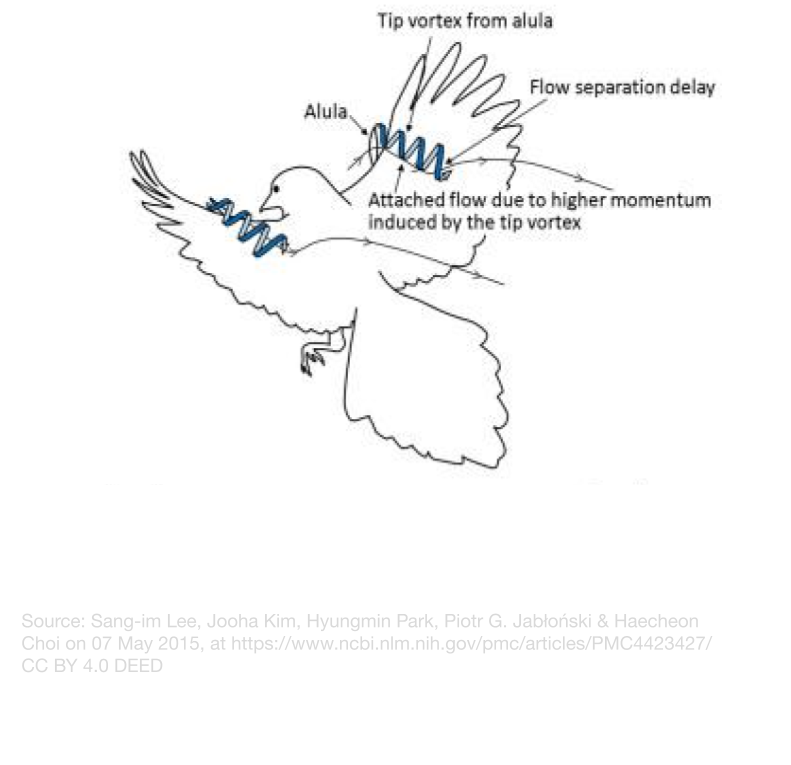
Bird Adaptations That Could Help
First evolved in the early Cretaceous in the early ancestor of birds Eoalulavis hoyasi, alulea are found on almost all modern flying birds, suggesting that they are crucial for bird flight. The alula is a small cluster of feathers attached to the “thumb” of the wing and acts as both a slat and a vortex generator when extended, much like modern aircraft. They act as a small wing, redirecting a high-pressure jet of air over the wing, and generating wingtip vortices in the same manner as discussed above. This allows birds to create lift and drag at high angles of attack without the airflow separating to achieve the fast and stationary landings that are required for their lifestyles.

Experts
To help me better understand my topic, I successfully contacted two experts, one for each major branch of my project.
For the aviation branch, I consulted Paul Gies, who was an expert I met while volunteering at the Avro Museum in Springbank. They are currently working on the Arrow II, which is a 60% scale recreation of the historic Canadian supersonic interceptor, the Avro Arrow. Paul Gies designed the aircraft by reconstructing the original blueprints of the Arrow and improving them with current technologies. For more information, check out their website. I mostly asked about the applicability of this technology in the current market, and he suggested that fixed-wing UAVs could be a good stepping stone to bring this technology to the market, as this sector requires less testing and is much more dynamic than others.
For the ornithology branch, I contacted Ivan Phillipsen, who has a PhD in zoology and a Master’s degree in biology, hosts The Science of Birds podcast, and is a tour guide with Wild Latitudes. In my questions, I focused on the evolution of bird flight and the differences between bird and aircraft wings.
Variables
Since the manipulated and control variables will change for every trial, I will only list the responding variables and some of the constant responding variables.
Responding Variables
I will be measuring these variables every trial, to allow easy comparison between the trials
-
Lift Produced
The lift produced is the amount of upward force generated by the wing. This also measures the amount of weight the wing can carry. I will be measuring the lift in newtons, which is about the force required to lift 100g in Earth’s gravity.
-
Lift to Wing Area ratio
The lift-to-wing-area ratio expresses how much lift each unit area of the wing is generating. This is useful, as it shows a more generalized view of the wing's effectiveness, and compensates for the uncontrolled area of the wing, especially for wings with wingtip slots. I will be using the unit N/m², which expresses how many newtons of lift the wing would produce if it had 1m² of surface area.
-
Stall Angle
The stall angle is the angle of attack at which airflow separation occurs, which was described in the background research. When the wing reaches this angle, it experiences a sudden drop in lift, which can be very dangerous for aircraft. I will be measuring the lift of the wing at increasing angles of attack until it drops, which will be the stall angle
Control Variables
These variables aren't consistent throughout the trials, as the manipulated variable changes every trial and the manipulated variable cannot be controlled, but here are some of the variables I control through all trials of the experiment:
- Basic Wing:
- Chord Length: 4cm
- Camber Length: 1cm
- Wing Span: 15 cm
- Wing cross section up until 5cm away from the wing root (Symmetrical)
- Airflow in wind tunnel (Max, Around 3.7 m/s)
Standardized Procedure
I will use these procedures consistently to determine and compare the lift produced, lift-to-wing-area ratio, and the stall angle of the wings in each iteration. In my procedure, I used my homebuilt wind tunnel. The build procedure can be found here.
Lift produced and Lift-to-Wing-Area Ratio Procedure
- Place the control airfoil in the wind tunnel lock, as shown:
- Set the angle of attack pointer to 10°
- Insert the cardboard spacing chip behind the angle of attack pointer to secure it
- Press zero on the lift scale
- Wait until the lift scale reading is stable
- Take note of the lift scale reading
- Set wind tunnel fan speed to 3
- If the scale reading does not change, the data collection system might be snagged in the cardboard notch, and nudge the data collection system into the wind.
- Wait until the lift scale reading is stable
- Take note of the lift scale reading
- Turn off the wind tunnel fan
- Remove the airfoil from the lock
- Repeat steps 1-12 with all remaining airfoils
- Repeat steps 1-13 for 3 trials, to ensure consistency
Stall Angle Procedure
I only ran this experiment for one trial because all data collected is either relative or qualitative.
Place the control airfoil in the wind tunnel lock, as done before
- Set the angle of attack pointer to 0°
- Insert the cardboard spacing chip behind the angle of attack pointer to secure it
- Press zero on the lift scale
- Wait until the lift scale reading is stable
- Take note of the lift scale reading
- Set wind tunnel fan speed to 3
- If the scale reading does not change, the data collection system might be snagged in the cardboard notch, and nudge the data collection system into the wind.
- Wait until the lift scale reading is stable
- Take note of the lift scale reading
- If data unclear, use thread and take note of airflow around the wing
- Turn off the wind tunnel fan
- Set the angle of attack pointer up a mark
- Repeat steps 1-12 until the pointer is at 90°
- Note the angle of attack
- Remove the airfoil from the lock
- Repeat steps 1-16 for all remaining airfoils
Iterations
Iteration 1
Inspiration: Rectangular, slotted wings of the Order Accipitriformes
Ideas
The order Accipitriformes contains most large birds of prey, including eagles, hawks, vultures, etc. They have slotted high-lift wings, suitable for low-power gliding and catching updrafts, and can create lift at low speeds while preventing vortex-induced drag. This is achieved using a deeply cambered wing with notches near the wingtip. These notches reduce the wingtip area, giving the air a smaller area to flow around and form vortices. The reduction in wingtip vortices not only reduces the drag caused by the creation of vortices, but also increases lift by increasing the pressure difference between the two sides of the wing.
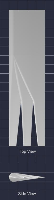
Test Models
|
Control Wing
|
1 Wingtip Slot |
2 Wingtip Slots |
Hypothesis
If the number of wing-tip slots increases, the lift will decrease slightly but the lift to wing area ratio will increase, because the wing will have less lift area, but also have less area overall, and less energy is wasted by generating wingtip vortices, leaving more energy for lift.
If the number of wing-tip slots increases, then the stall angle will remain the same, because even at the wing tips, the individual wing cross sections are always congruent, and airflow will separate at the same angle.
Variables
Manipulated: Number of wing tip slots (0,1,2)
Responding:
- Lift to Wing Area ratio
- Lift Produced
- Stall Angle
Controlled:
- Basic Wing
- Chord Length: 4cm
- Camber Length: 1cm
- Wing Span: 15 cm
- Wing cross section up until 5cm away from the wing root (Symmetrical)
- Wingtip SLots
- Transitional area to the wing tip slots (Tapering airfoils “clipped” together)
- Shape of wing tip slots: Triangular, airfoil splits into smaller, tapered airfoil
- Wing tip slot depth (5cm)
- Air speed (Maximum possible speed
Materials
- Small wind tunnel with adjustable angle of attack and lift reading
- 3-D printed models of 4 identical airfoils with 0,1 or 2 wing tip slots
- Red sewing thread attached to the end of a skewer
- Cardboard spacer chip
Procedure
The standardized procedure was used, and can be found here.
Observations
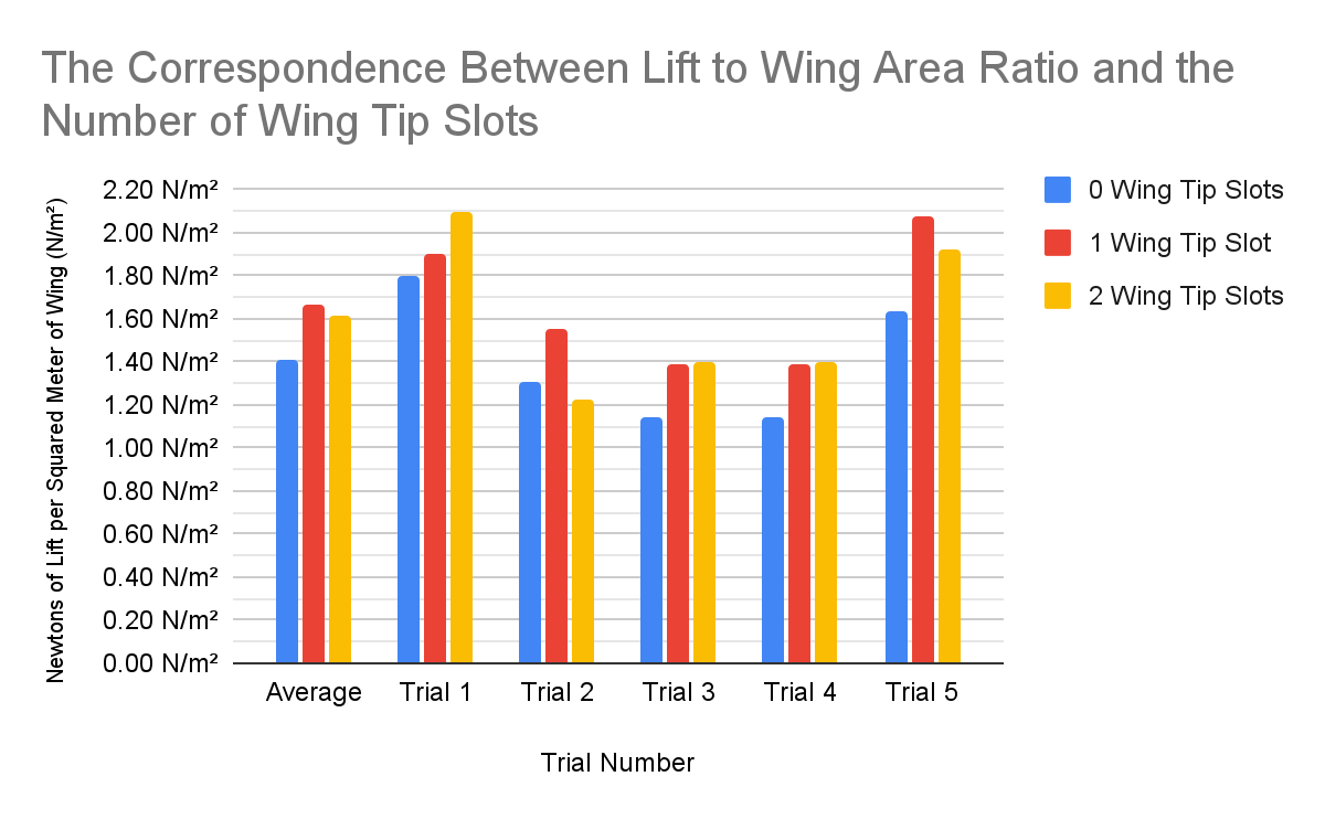
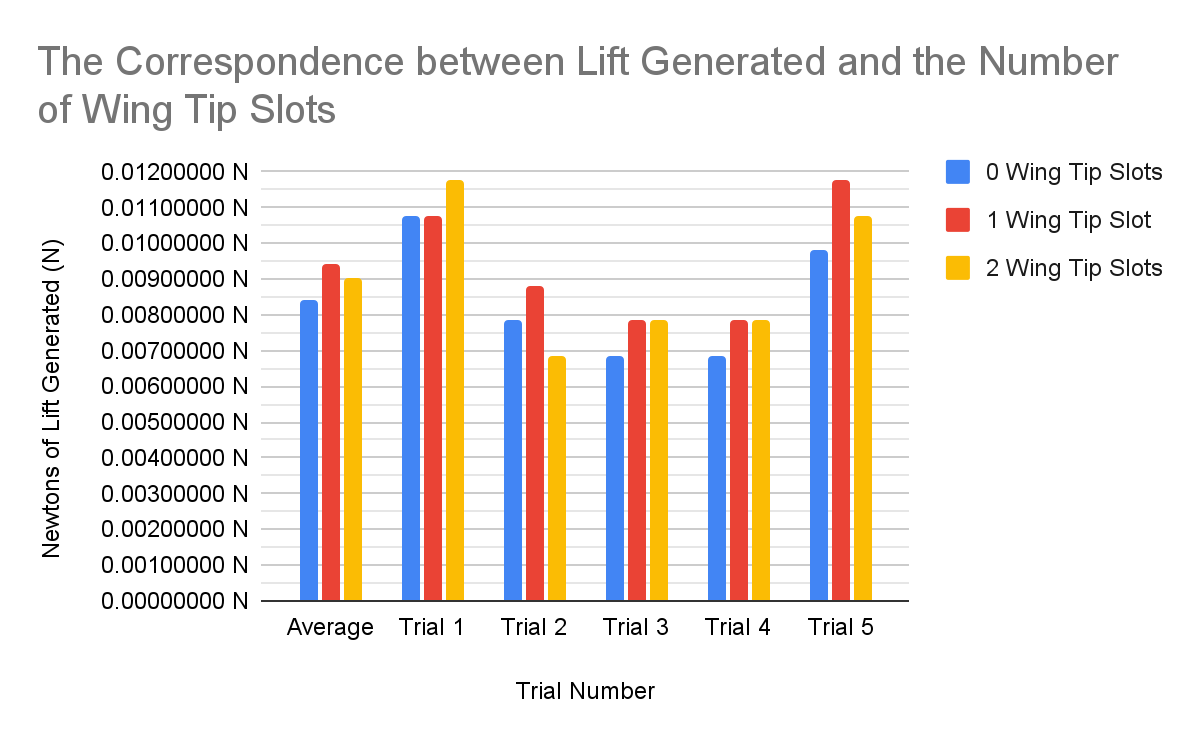
The Impact Of Added Wingtip Slots On The Lift-to-wing-area Ratio and the Lift Produced:
| Trial | Wing tip Slots | Wing Area | Scale Reading (No Wind) | Scale Reading (With Wind) | Lift (In Newtons) | Lift (in Newtons) to Wing Area |
|
1 |
0 | 60.00 cm² | 0.00 g | -1.10 g | 0.011 N | 1.7978858 N/m² |
| 1 | 56.67 cm² | 0.00 g | -1.10 g | 0.011 N | 1.9036438 N/m² | |
| 2 | 56.00 cm² | 0.00 g | -1.20 g | 0.012 N | 2.1014250 N/m² | |
|
2 |
0 | 60.00 cm² | 0.00 g | -0.80 g | 0.008 N | 1.3075533 N/m² |
| 1 | 56.67 cm² | 13.00 g | 12.10 g | 0.009 N | 1.5575268 N/m² | |
| 2 | 56.00 cm² | 0.00 g | -0.70 g | 0.007 N | 1.2258313 N/m² | |
|
3 |
0 | 60.00 cm² | 5.70 g | 5.00 g | 0.007 N | 1.1441092 N/m² |
| 1 | 56.67 cm² | 5.60 g | 4.80 g | 0.008 N | 1.3844682 N/m² | |
| 2 | 56.00 cm² | 26.60 g | 25.80 g | 0.008 N | 1.4009500 N/m² | |
|
4 |
0 | 60.00 cm² | -0.70 g | -1.40 g | 0.007 N | 1.1441092 N/m² |
| 1 | 56.67 cm² | 0.00 g | -0.80 g | 0.008 N | 1.3844682 N/m² | |
| 2 | 56.00 cm² | 3.10 g | 2.30 g | 0.008 N | 1.4009500 N/m² | |
|
5 |
0 | 60.00 cm² | 0.00 g | -1.00 g | 0.010 N | 1.6344417 N/m² |
| 1 | 56.67 cm² | 1.20 g | 0.00 g | 0.012 N | 2.0767024 N/m² | |
| 2 | 56.00 cm² | 0.60 g | -0.50 g | 0.011 N | 1.9263063 N/m² | |
|
AVG |
0 | 60.00 cm² | 1.00 g | 0.14 g | 0.008 N | 1.4056198 N/m² |
| 1 | 56.67 cm² | 3.96 g | 3.00 g | 0.009 N | 1.6613619 N/m² | |
| 2 | 56.00 cm² | 6.06 g | 5.14 g | 0.009 N | 1.6110925 N/m² | |
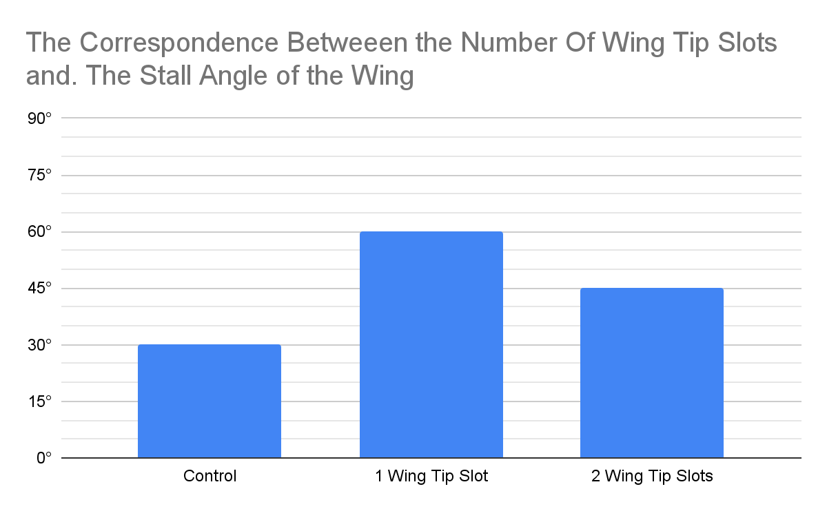
The Impact of Added Wingtip Slots on The Stall Angle of The Wing:
| Alula Angle | Stall Angle |
| Control | 30° |
| 1 Wing Tip Slot | 60° |
| 2 Wing Tip Slots | 45° |
Analysis
Overall, the wing with 1 wing tip slot performed the best in both lift and lift-to-wing-area ratio. Trail 1 seems to be an outlier because every wing performed much better than trials 2,3 and 4, and the lift produced by 2 wing tip slots exceeds the lift produced by 1 wing tip slots more than others. This might have been caused by the data collection system slider being stiffer or looser than usual. Trial 5 might also be an outlier because of similar reasons, except for the large jump in lift with 1 wing tip slot. The results of trials 3 and 4 are exactly the same, which might be a coincidence, or they might have been controlled very well.
The wing with one wing tip slot also had the highest stall angle, and the control had the lowest. I had a problem with the high drag of the wings causing the data collection system to catch in its notch, disabling the scale readings
Conclusion
My hypothesis was partially correct because the lift-to-wing-area ratio did increase when wingtip slots were first added, but decreased when the second slot was added, contrary to my hypothesis, which predicted that the lift-to-wing-area ratio would always increase with added wingtip slots. My hypothesis also predicted that the lift would decrease slightly as the number of wing tip slots increased, but in reality, the lift followed a similar pattern to the lift-to-wing-area ratio.
My second hypothesis was incorrect because the wing with 1 wingtip slot had the highest stall angle. This might be due to the front “Feather” acting like a leading edge slot. Which forces a jet of high-pressure air over the second “Feather”, preventing air separation even after the main wing stalls. According to this, the same effect should be working on the wing with 2 wing tip slots, but it still has a lower stall angle. This might be because the “Feathers” are too thin to produce sufficient lift after the main wing stalls.
Overall, an added wing tip slot greatly improved the performance of the wing, and could be used to replace bulky winglets and wind fences.
Extension
From my background research, the addition of wing tip slots increases the pressure differential, and with it, lift, by reducing the wing tip area for air to go around. I might try to change the area of the wingtip by adjusting the taper of the “Feathers”, and see how that affects lift. I might also replicate the upward curve of eagle feathers, much like current winglets. Another way I could replicate the wings of large raptors is to use “Square” notches instead of the triangular ones I’m using now, which will allow for more even airflow through the slot, and reduce drag caused by air flowing through the narrow part of the slot. I could also reduce the wing tip area by tapering the wing to a sharp point, like on high-speed found on terns and falcons
Iteration 2
Inspiration: Alulea, found in almost all flying birds, first evolved during the early Cretaceous.
Ideas
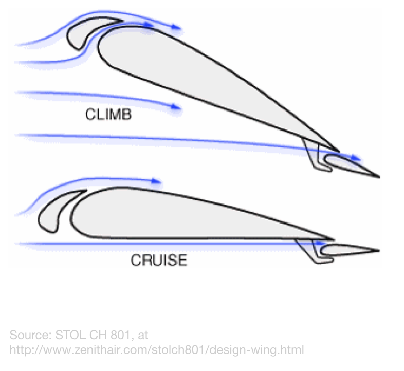
On a bird’s wing, the alula is a small piece of the wing attached to its “Thumb”. It is raised during landing to form a slot, much like leading edge slots and vortex generators on today’s aircraft, to prevent airflow separation and extra drag at high angles of attack by shooting a jet of high-pressure air over the upper surface of the wing to reinforce the Coanda effect and generate vortices over the wing to increase the air’s momentum. During regular flight, the alulea are typically flattened to the wing to reduce drag. Alulea seem to be a crucial part of flight, as they evolved very early in bird evolution, and are much better at preventing airflow separation than leading edge slots, as seen during the high angle-of-attack landings that birds require.
Adding alulea to the wings of aircraft. could allow higher angle-of-attack, and therefore shorter landings.
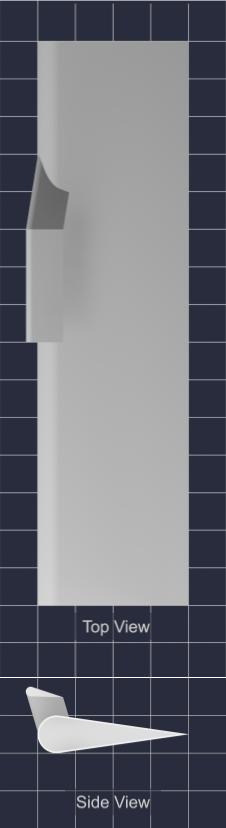
Test Models
|
|
-20° Alula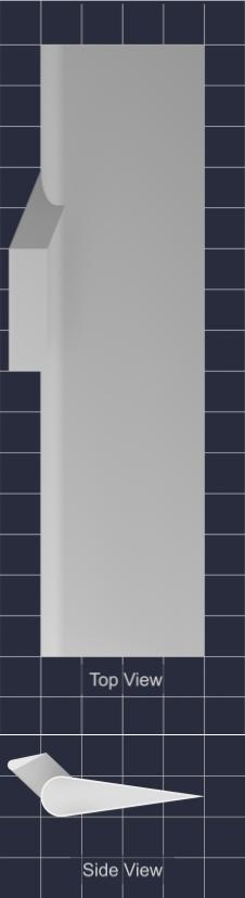 |
-10° Alula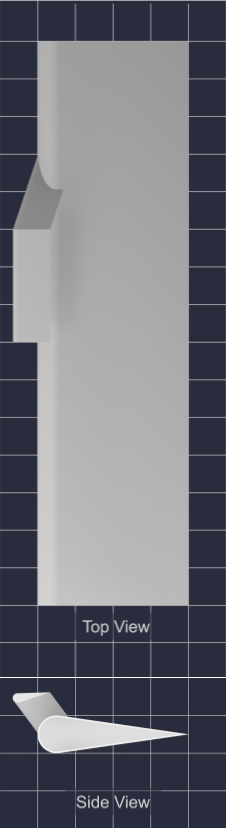 |
0° Alula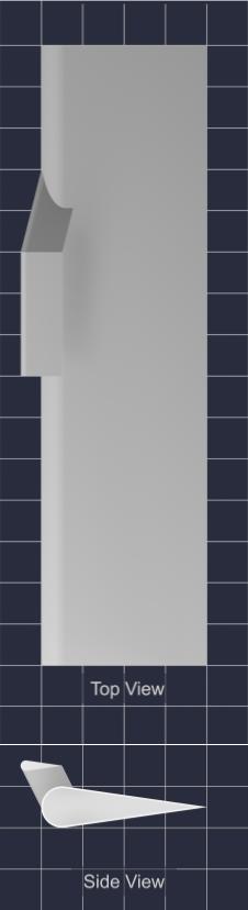 |
10° Alula |
Variables
Manipulated: Alula Angle (-20°,-10°,0°,10°)
Responding:
- Lift to Wing Area ratio
- Lift Produced
- Stall Angle
Controlled:
- Basic Wing:
- Chord Length: 4cm
- Camber Length: 1cm
- Wing Span: 15 cm
- Wing cross section up until 5cm away from the wing root (Symmetrical)
- Alula Shape
- Chord Length: 1cm
- Camber Length: 0.25cm
- Wing Span: 3 cm
- Wing cross section up until 5cm away from the wing root (Symmetrical)
- Airflow in wind tunnel (Max)
Materials:
- Small wind tunnel with adjustable angle of attack and lift reading
- 3-D printed models of 4 identical airfoils with alulea that have -20°, -10°, 0°, and 10° alula angles
- 3-D printed model of control airfoil
- Cardboard spacer chip
Procedure
The standardized procedure was used, and can be found here.
Observations
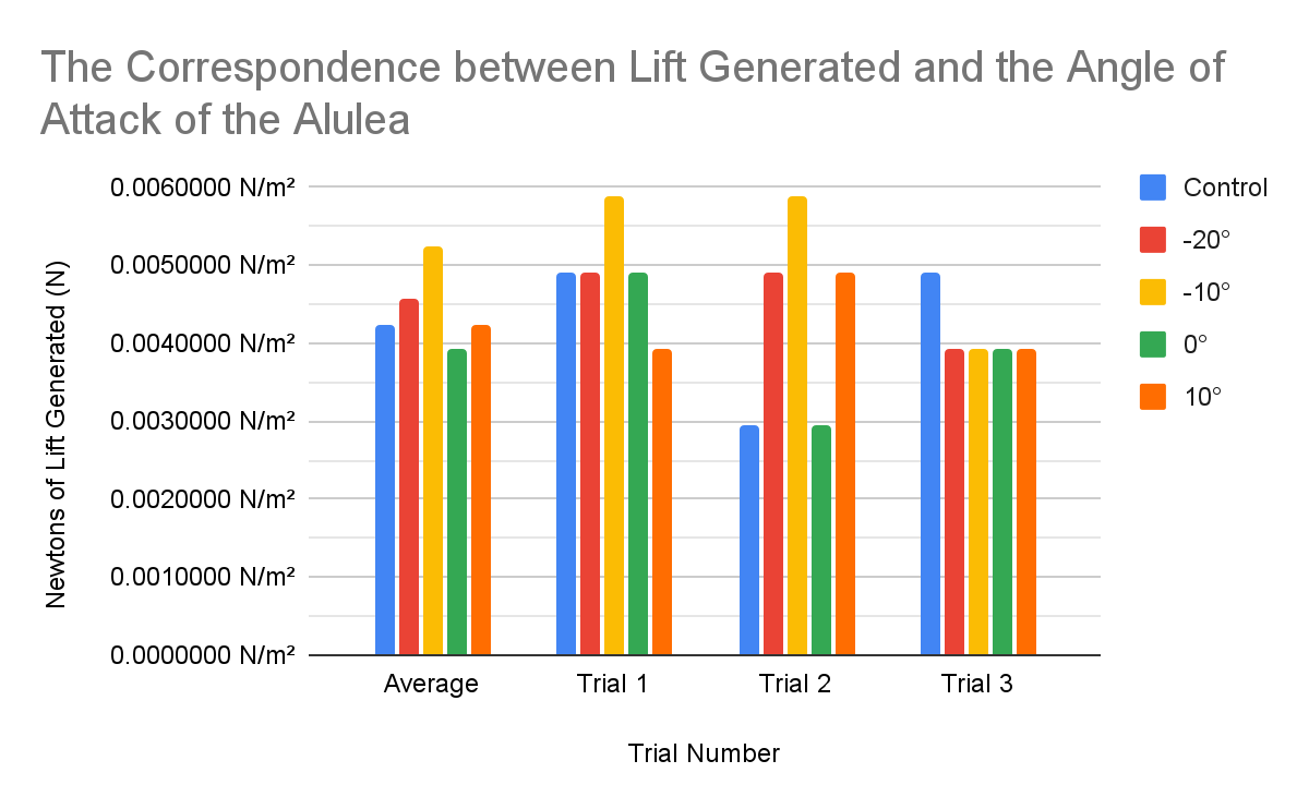
The Effects of Different Alula Angles on The Lift-to-Wing-Area Ratio and The Lift Produced:
| Trial | Alula AOA° | Wing Area | Scale Reading (No Wind) | Scale Reading (With Wind) | Lift (In Newtons) | Lift (in Newtons) to Wing Area |
|
1 |
Control | 60.00 cm² | -1.70 g | -2.20 g | 0.005 N | 0.8172208 N/m² |
| -20° | 60.00 cm² | 0.50 g | 0.00 g | 0.005 N | 0.8172208 N/m² | |
| -10° | 60.00 cm² | -1.20 g | -1.80 g | 0.006 N | 0.9806650 N/m² | |
| 0° | 60.00 cm² | 4.20 g | 3.70 g | 0.005 N | 0.8172208 N/m² | |
| 10° | 60.00 cm² | 1.2 | 0.8 | 0.004 N | 0.6537767 N/m² | |
|
2 |
Control | 60.00 cm² | -1.00 g | -1.30 g | 0.003 N | 0.4903325 N/m² |
| -20° | 60.00 cm² | -4.40 g | -4.90 g | 0.005 N | 0.8172208 N/m² | |
| -10° | 60.00 cm² | -0.60 g | -1.20 g | 0.006 N | 0.9806650 N/m² | |
| 0° | 60.00 cm² | 2.00 g | 1.70 g | 0.003 N | 0.4903325 N/m² | |
| 10° | 60.00 cm² | -3.9 | -4.4 | 0.005 N | 0.8172208 N/m² | |
|
3 |
Control | 60.00 cm² | -1.90 g | -2.40 g | 0.005 N | 0.8172208 N/m² |
| -20° | 60.00 cm² | -2.70 g | -3.10 g | 0.004 N | 0.6537767 N/m² | |
| -10° | 60.00 cm² | -0.60 g | -1.00 g | 0.004 N | 0.6537767 N/m² | |
| 0° | 60.00 cm² | -0.40 g | -0.80 g | 0.004 N | 0.6537767 N/m² | |
| 10° | 60.00 cm² | -6.7 | -7.1 | 0.004 N | 0.6537767 N/m² | |
|
AVG |
Control | 60.00 cm² | -1.53 g | -1.97 g | 0.004 N | 0.7082581 N/m² |
| -20° | 60.00 cm² | -2.20 g | -2.67 g | 0.005 N | 0.7627394 N/m² | |
| -10° | 60.00 cm² | -0.80 g | -1.33 g | 0.005 N | 0.8717022 N/m² | |
| 0° | 60.00 cm² | 1.93 g | 1.53 g | 0.004 N | 0.6537767 N/m² | |
| 10° | 60.00 cm² | -3.13 g | -3.57 g | 0.004 N | 0.7082581 N/m² | |
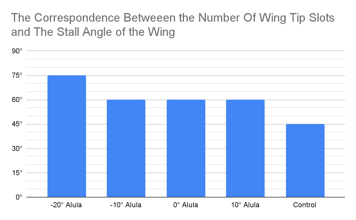
The Effects of Different Alula Angles on The Stall Angle of the Wing
| Alula Angle | Stall Angle |
| -20° Alula | 75° |
| -10° Alula | 60° |
| 0° Alula | 60° |
| 10° Alula | 60° |
| Control | 45° |
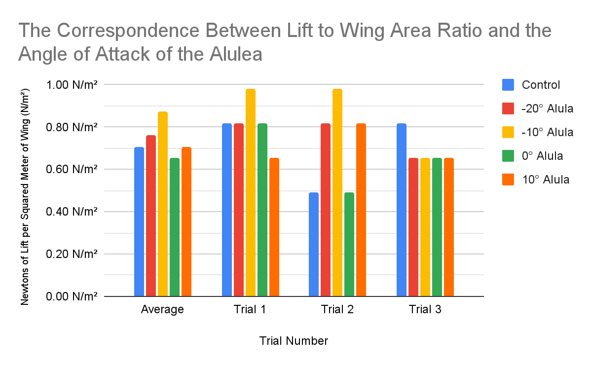
Analysis
At the angle of attack of 10°, the wing with a -10° alula created the most lift. This could be because the alula would be at a 0° angle of attack, which prevents disruption of airflow over the main wing. Airflow around the wing with the -20° alula might have not flowed into the slot formed by the wing, instead flowing around the alula, effectively expanding the wing. Both the 0° and 10° alulea could have caused enough disruption to reduce the lift of the wing, but the 10° alula might have also created enough lift to compensate as a regular airfoil.
In all the stall angle tests, the lift increases as the angle of attack increases, and then stops increasing or decreases when the wing stalls. The addition of alulea delays stalling, and reduces the amount of lift lost when the wing does stall. The -20° alula stalled last because more of the alula was in direct airflow when the wing is at a high angle of attack, and still be effective when other alulea are blocked by the main wing.
Conclusion
My first hypothesis was correct, because added alulea increased the stall angle, and the stall angle increased as the alula angle decreased.
My second hypothesis was incorrect because the lift didn’t increase with the alula angle of attack all the time. Instead, the -10° alula performed the best, possibly because it has a 0° angle of attack when the wing is at a 10° angle of attack. The 10° alula was an improvement from the 0° alula, but not large enough of an improvement to overtake the -10° alula.
Extension
The alulea as tested here can be used to prevent stalling during takeoffs and landings, when the wings are the most susceptible to stalling because of the high angles of attack and low speed. Alulea could also allow aircraft to fly at even higher angles of attack during landing, which means that they can still create lift at low speeds, and therefore land on shorter runways.
I could test the interactions between the alula and the wingtip slots in future experiments, and tweak the alula to create more lift or wingtip vortices, and increase the stall angle further.
Iteration 3
Inspiration: Wingtip slots formed by individual flexible feathers and winglets of modern aircraft
Ideas
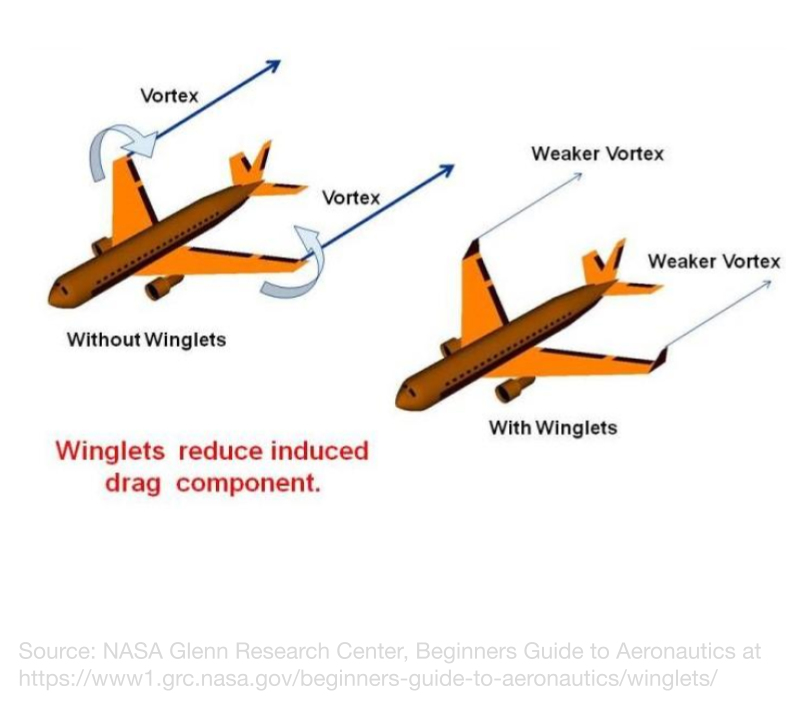
After the success of wing tip slots in iteration 1, I want to improve on that design with some extra vortex-reducing wingtip devices. In both current aircraft and some gliding birds, the wingtips are curved upwards, forcing high-pressure air to move up to the wingtips to reach the low-pressure zone, and also reduce the pressure differential between the top and bottom surfaces of the wingtips. These are called winglets and help maintain the pressure differential between the wing surfaces, and reduce the creation of wingtip vortices. By doing this, the winglets can help the wing generate more lift while reducing drag.
Test Models
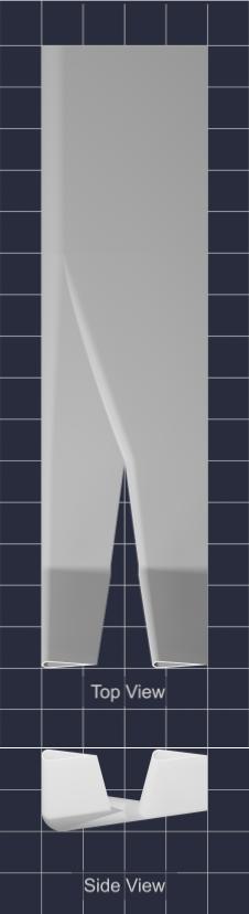
Control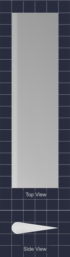 |
Without Winglets |
With Winglets |
Hypothesis
If the winglet-like tips are added to the “Feathers” of the slotted airfoil, then the lift produced and the lift-to-wing-area ratio will increase because the curved winglet provides a pressure gradient to the wingtips, and forces high-pressure air to move further before reaching the low-pressure zone, both of which increase the pressure difference between the upper and lower parts of the wing, and reduce wingtip vortices.
If the winglet-like tips are added to the “Feathers” of the slotted airfoil, then the stall angle will remain the same, because the airfoil’s cross-section will remain the same, and not change the airflow around itself.
Variables
Manipulated: Winglet Present
Responding:
- Lift to Wing Area ratio
- Lift Produced
- Stall Angle
Controlled:
- Basic Wing:
- Chord Length: 4cm
- Camber Length: 1cm
- Wing Span: 15 cm
- Wing cross section up until 5cm away from the wing root (Symmetrical)
- 1 wing tip slot
- Winglet Angle (30°)
- Airflow in wind tunnel (Max)
Materials:
- Small wind tunnel with adjustable angle of attack and lift reading
- 3-D printed models of 2 identical airfoils with 1 wingtip slot, but one has winglets
- 3-D printed model of control airfoil
- Cardboard spacer chip
Procedure
The standardized procedure was used, and can be found here.
Observations
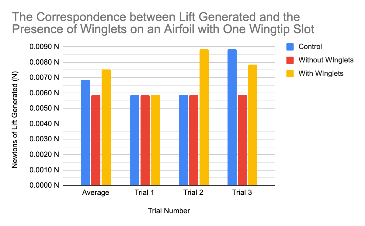
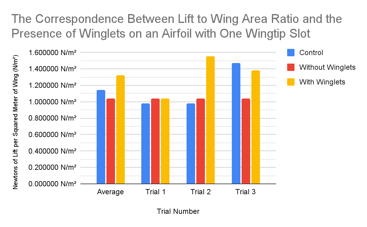
How The Presence of Added Winglets Affects The lift-to-wing Area Ratio and The Lift Produced:
| Trial | Alula AOA° | Wing Area | Scale Reading (No Wind) | Scale Reading (With Wind) | Lift (In Newtons) | Lift (in Newtons) to Wing Area |
|
1 |
Control | 60.00 cm² | 0.60 g | 0.00 g | 0.006 N | 0.9806650 N/m² |
| Without WInglets | 56.67 cm² | 1.40 g | 0.80 g | 0.006 N | 1.0383512 N/m² | |
| With WInglets | 56.67 cm² | 0.60 g | 0.00 g | 0.006 N | 1.0383512 N/m² | |
|
2 |
Control | 60.00 cm² | 0.60 g | 0.00 g | 0.006 N | 0.9806650 N/m² |
| Without WInglets | 56.67 cm² | 0.60 g | 0.00 g | 0.006 N | 1.0383512 N/m² | |
| With WInglets | 56.67 cm² | 0.50 g | -0.40 g | 0.009 N | 1.5575268 N/m² | |
|
3 |
Control | 60.00 cm² | 0.00 g | -0.90 g | 0.009 N | 1.4709975 N/m² |
| Without WInglets | 56.67 cm² | 0.60 g | 0.00 g | 0.006 N | 1.0383512 N/m² | |
| With WInglets | 56.67 cm² | 3.90 g | 3.10 g | 0.008 N | 1.3844682 N/m² | |
|
AVG |
Control | 60.00 cm² | 0.40 g | -0.30 g | 0.007 N | 1.1441092 N/m² |
| Without WInglets | 56.67 cm² | 0.87 g | 0.27 g | 0.006 N | 1.0383512 N/m² | |
| With WInglets | 56.67 cm² | 1.67 g | 0.90 g | 0.008 N | 1.3267821 N/m² | |
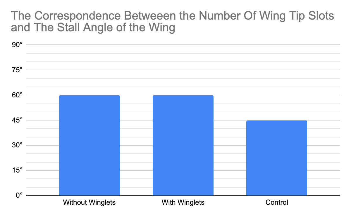
The Impact Of the Presence of Winglets On the Stall Angle of a Wing With 1 Wingtip Slot
| Alula Angle | Stall Angle |
| Without Winglets | 60° |
| With Winglets | 60° |
| Control | 45° |
Analysis
Contrary to previous tests, the wing with one wingtip slot performed worse than the control airfoil in both the lift and lift-to-wing-area ratio tests, but the winglets compensated for this loss of lift, performing even better than the control airfoil. This loss of lift could be caused by the uneven airflow throughout the triangular wing slot, especially through the wider portion. This could be optimized with a rectangular slot, like found on large gliding raptors. The extra lift generated by the winglets could have been due to the winglets reinforcing the vortex-reducing effect created by the wingtip slots, but also doesn’t let too much airflow through the larger parts of the wingtip slot, as the winglets don’t generate a large pressure differential.
There is not much of a pattern between the trials, but the relations between the different wings seem similar for each trial. The small inconsistencies in the lift readings between trials could have been caused by inaccuracies in the scale readings or changes in the data collection system slider. These inconsistencies would be reduced by averaging out the trials.
All the lift at different angles of attack followed a similar pattern, increasing until the stall angle, then decreasing. The wings with two wingtip slots performed the same in terms of stall angle, as their slots work in the same way to prevent airflow separation
Conclusion
Both of my hypotheses were correct, as the lift and stall angle did increase with the introduction of the wingtip slot and winglets. This is because of the wingtip slots and winglets prevent the loss of the pressure difference over the two wing surfaces, and the wingtip slots increase the inertia of the airflow over the upper wing surface. Along with this, the curved wingtip would also form a dihedral, which keeps the aircraft stable in the roll axis by providing offset lift.
Overall, the addition of a “Feather-like” wingtip improved the wing’s lift and stability greatly.
Extension
I might try to change the area of the wingtip by adjusting the taper of the “Feathers”, and see how that affects lift, or narrow the tip to a point, to eliminate the wingtip completely. I could also adapt the square slots mentioned earlier, to ensure optimal airflow throughout the slot.
Iteration 4
Milestone Test to test all Adaptations
Ideas
This test will be combining all previous features to compare the past trials to the current wing.
Test Models
|
Control |
With Bird Addaptations |

Hypothesis
If adaptations found on birds that assist flight are added to traditional airfoils, then the lift, lift-to-wing-area ratio, and stall angle will increase because throughout their 60 million years of evolution, birds have evolved adaptations that suit their individual lifestyles, many of which require more versatile and efficient wings than today’s aircraft.
Variables
Manipulated: Presence of added bird addaptations
Responding:
- Lift to Wing Area ratio
- Lift Produced
- Stall Angle
Controlled:
- Basic Wing:
- Chord Length: 4cm
- Camber Length: 1cm
- Wing Span: 15 cm
- Wing cross section up until 5cm away from the wing root (Symmetrical)
- 1 wing tip slot
- Winglet Angle (30°)
- Airflow in wind tunnel (Max)
Materials:
- Small wind tunnel with adjustable angle of attack and lift reading
- 3-D printed model of control airfoil with 1 wingtip slot, a -20° alula, and winglets.
- 3-D printed model of control airfoil
- Cardboard spacer chip
Procedure
The standardized procedure was used, and can be found here.
Observations
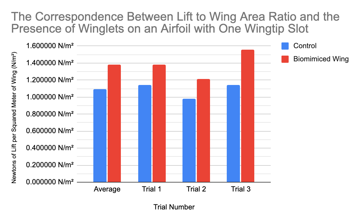
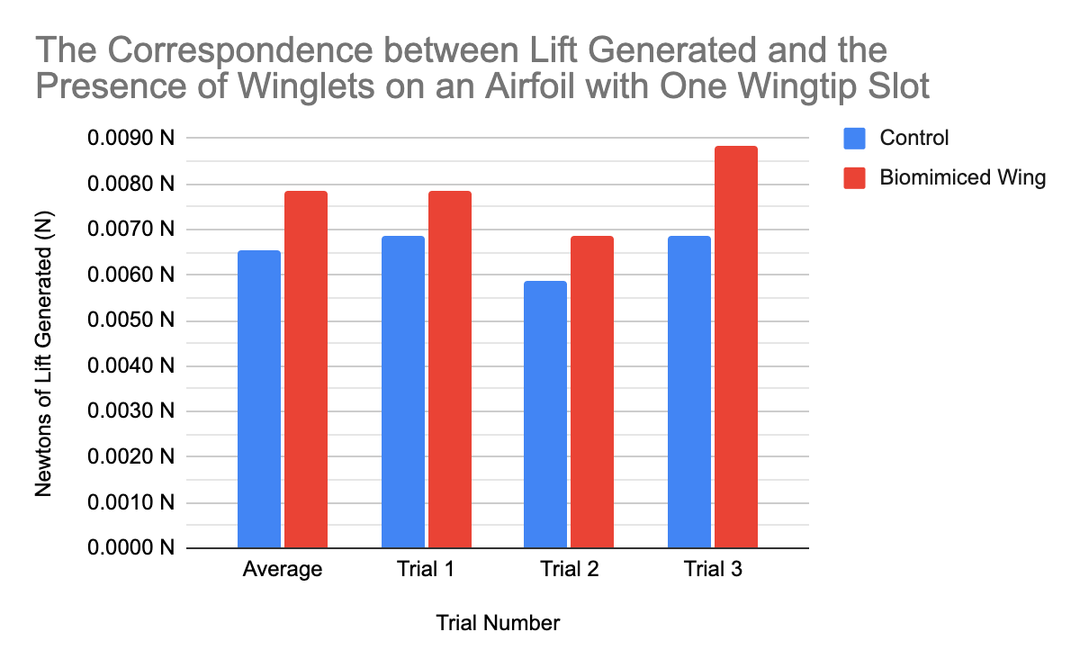
How the Addition of Bird Addaptations affects the lift-to-wing area ratio and the lift produced:
| Trial | Alula AOA° | Wing Area | Scale Reading (No Wind) | Scale Reading (With Wind) | Lift (In Newtons) | Lift (in Newtons) to Wing Area |
|
1 |
Control | 60.00 cm² | 0.70 g | 0.00 g | 0.0069 N | 1.1441092 N/m² |
| Biomimiced Wing | 56.67 cm² | 0.80 g | 0.00 g | 0.0078 N | 1.3844682 N/m² | |
|
2 |
Control | 60.00 cm² | 3.60 g | 3.00 g | 0.0059 N | 0.9806650 N/m² |
| Biomimiced Wing | 56.67 cm² | 3.70 g | 3.00 g | 0.0069 N | 1.2114097 N/m² | |
|
3 |
Control | 60.00 cm² | 0.70 g | 0.00 g | 0.0069 N | 1.1441092 N/m² |
| Biomimiced Wing | 56.67 cm² | 2.00 g | 1.10 g | 0.0088 N | 1.5575268 N/m² | |
|
AVG |
Control | 60.00 cm² | 1.67 g | 1.00 g | 0.0065 N | 1.0896278 N/m² |
| Biomimiced Wing | 56.67 cm² | 2.17 g | 1.37 g | 0.0078 N | 1.3844682 N/m² | |
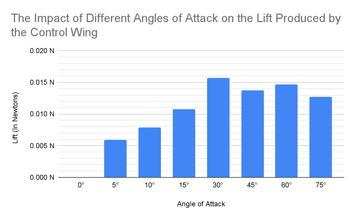
The Effects of Different Angles of Attack on Lift and Airflow Around the Control Wing
| Angle of Attack | Scale Reading (No Wind) | Scale Reading (With Wind) | Lift (In Newtons) | Airflow (Qualitative) |
| 0° | 0.90 g | 0.90 g | 0.000 N | Airflow is laminar and barely affected by the wing |
| 5° | 0.00 g | -0.60 g | 0.006 N | Airflow is laminar and slightly deflected by the wing |
| 10° | 0.80 g | 0.00 g | 0.008 N | Airflow is slightly turbulent, but still mostly laminar, and follows the airfoil shape |
| 15° | 0.40 g | -0.70 g | 0.011 N | Airflow is slightly turbulent, but still mostly laminar, and follows the airfoil shape |
| 30° | 0.80 g | -0.80 g | 0.016 N | Airflow is slightly turbulent, but still mostly laminar, and clearly follows the airfoil shape |
| 45° | 0.50 g | -0.90 g | 0.014 N | The airflow is very turbulent, and spanwise flow is present near the wingtips |
| 60° | 0.30 g | -1.20 g | 0.015 N | The airflow is very turbulent, and air flows backwards over and after the wing |
| 75° | 0.00 g | -1.30 g | 0.013 N | The airflow is very turbulent, and air flows backwards after the wing |
| Stall Angle: | 45° |
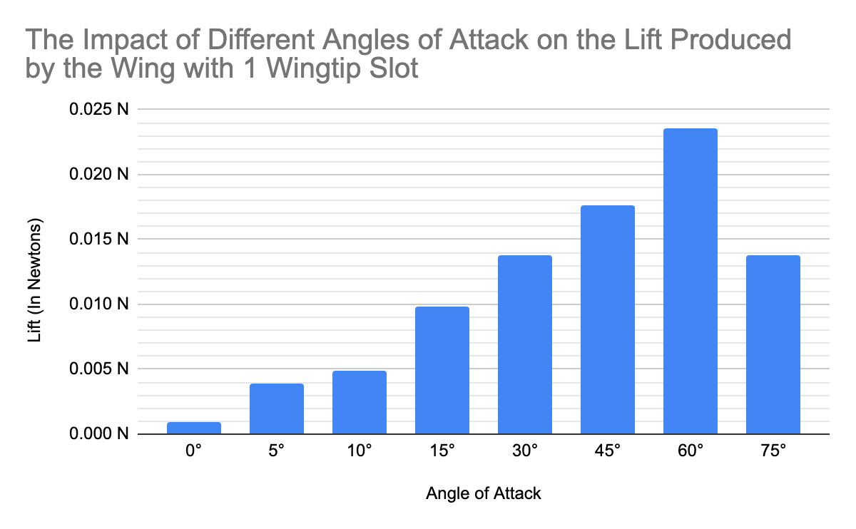
The Effects of Different Angles of Attack on Lift and Airflow Around a Wing With Added Bird Adaptations
| Angle of Attack | Scale Reading (No Wind) | Scale Reading (With Wind) | Lift (In Newtons) | Airflow (Qualitative) |
| 0° | 1.30 g | 1.20 g | 0.001 N | Airflow is laminar and bariley affected by the wing. Airflow also flows over the alula |
| 5° | 1.50 g | 1.10 g | 0.004 N | Airflow is laminar and bariley affected by the wing. Airflow also flows over the alula |
| 10° | 1.50 g | 1.00 g | 0.005 N | Airflow is laminar and slightly deflected by the wing. Airflow also flows over the alula |
| 15° | 1.00 g | 0.00 g | 0.010 N | Airflow is laminar and follows the shape of the wing. Spanwise flow by the alula tip is also present. |
| 30° | 1.40 g | 0.00 g | 0.014 N | Airflow is laminar and follows the shape of the wing. Spanwise flow by the alula tip is also present. |
| 45° | 1.80 g | 0.00 g | 0.018 N | Airflow is turbulant, but more lamniar over the alula. Spanwise flow by the alula tip is also present. |
| 60° | 2.40 g | 0.00 g | 0.024 N | Airflow is very turbulant, and flow backwards sometimes, but less so over the alula. Spanwise flow by the alula tip is also present. |
| 75° | 1.40 g | 0.00 g | 0.014 N | Airflow is very turbulant, and flow backwards sometimes over the whole wing. |
| Stall Angle: | 75° |
The Effects of Added Bird Adaptations on the Stall Angle of a Traditional Airfoil
| Alula Angle | Stall Angle |
| Control | 45° |
| Biomimiced wing | 75° |
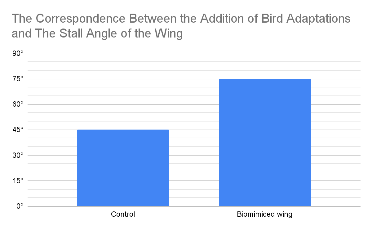
Analysis
Over all three trials, the biomimiced wing generated an average of 27% more lift than the traditional airfoil. This trend was very regular over all three trials, except for trial 3, where the biomimiced airfoil generated 37% more lift than the traditional airfoil. This increase of lift is caused by the winglets and wingtip slot preventing the production of wingtip vortices and maintaining the pressure differential by reducing the wingtip area for vortices to form, and reducing the pressure differential near the wingtip. The alula was also in front of the wing, which might have extended the effective lift area of the wing. The winglets also provide the added benefit of adding a small dihedral, which prevents the aircraft from rolling, providing stability.
The stall angle also surpassed the control airfoil by almost 2 times. This could be because the alula and the wingtip slot shoot a high-pressure jet of air along most of the wing, which reinforces the Coanda effect, and keeps air stuck to the upper surface of the wing. The wing slots means that most of the wing was still generating lift, which resulted in a maximum lift of 0.024N, compared to a peak lift of 0.015N with only alulea. This could allow the wing to land at very low speeds at a high angle of attack, reducing the area required for landing.
Overall, the addition of bird adaptations greatly boosts the performance of the wing, making it more stable and efficient.
Conclusion
My hypothesis was correct, as the added bird adaptations did substantially improve the wing’s lift, lift-to-weight ratio, and stall angle. The lift produced by the wing with bird adaptations was consistently around 27% higher than the control wing, which means that the bird wing could create more lift than the control wing could at the same speed. In addition, the bird wing only stalled and lost lift at a 75° angle of attack, while the control wing stalled at 45°. Just before stalling, the bird wing generated a peak lift of 0.024N, while the control wing only reached 0.016N. This amount of high lift and stall angle is useful for short landings, where the aircraft has to create enough lift to support its weight, but also is moving very slowly at a high angle of attack.
Iteration 5
Inspiration: Rectangular, slotted wings of the Order Accipitriformes
Ideas
As before, the order Accipitriformes contains most large birds of prey, including eagles, hawks, vultures, etc. They have slotted high-lift wings and need to conserve speed while creating high lift because of their gliding lifestyle. For this, they have rectangular wingtip slots, which are the most effective shape of wingtip slot, increasing lift and reducing drag. This is because the base of the slot is wider in rectangular slots, and air can move through the slot with less friction. Many other small forest birds that have elliptical wings, such as sparrows, have less efficient elliptical slots to maximize lift from their small wings. The least efficient and earliest evolved slots were triangular like the ones that I tested initially, and are found in birds that don't make use of wingtip slots often.
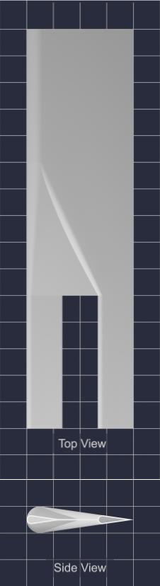
Test Models:
| Control |
Triangular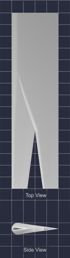 |
Elliptical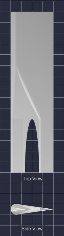 |
Square |
Hypothesis
If a square wingtip slot is added, then the lift and lift-to-wing area ratio will increase because the wingtip slot would reduce the generation of wingtip vortices, which will maintain the pressure differential and increase lift. Vortices generated by the flat base of the slot will be recaptured by the trailing “Feather” to further increase lift.
If a square wingtip slot is added, then the stall angle will increase, because the whole slot will be optimally spaced, and a high-pressure jet of air will be shot along the whole trailing wing, instead of just the wingtip with the triangular slots.
Variables
Manipulated: Shape of Wingtip Slot (Triangular, Elliptical, Rectangular)
Responding:
- Lift to Wing Area ratio
- Lift Produced
- Stall Angle
Controlled:
- Basic Wing:
- Chord Length: 4cm
- Camber Length: 1cm
- Wing Span: 15 cm
- Wing cross section up until 5cm away from the wing root (Symmetrical)
- 1 wing tip slot
- Wingtip Slot
- Depth: 5 cm
- Width: 1⅓ cm
- Airflow in wind tunnel (Max)
Materials:
- Small wind tunnel with adjustable angle of attack and lift reading
- 3-D printed models of 3 identical airfoils with different wingtip slot shapes (Triangular, Elliptical, Rectangular)
- 3-D printed model of control airfoil
- Cardboard spacer chip
Procedure
The standardized procedure was used, and can be found here.
Observations
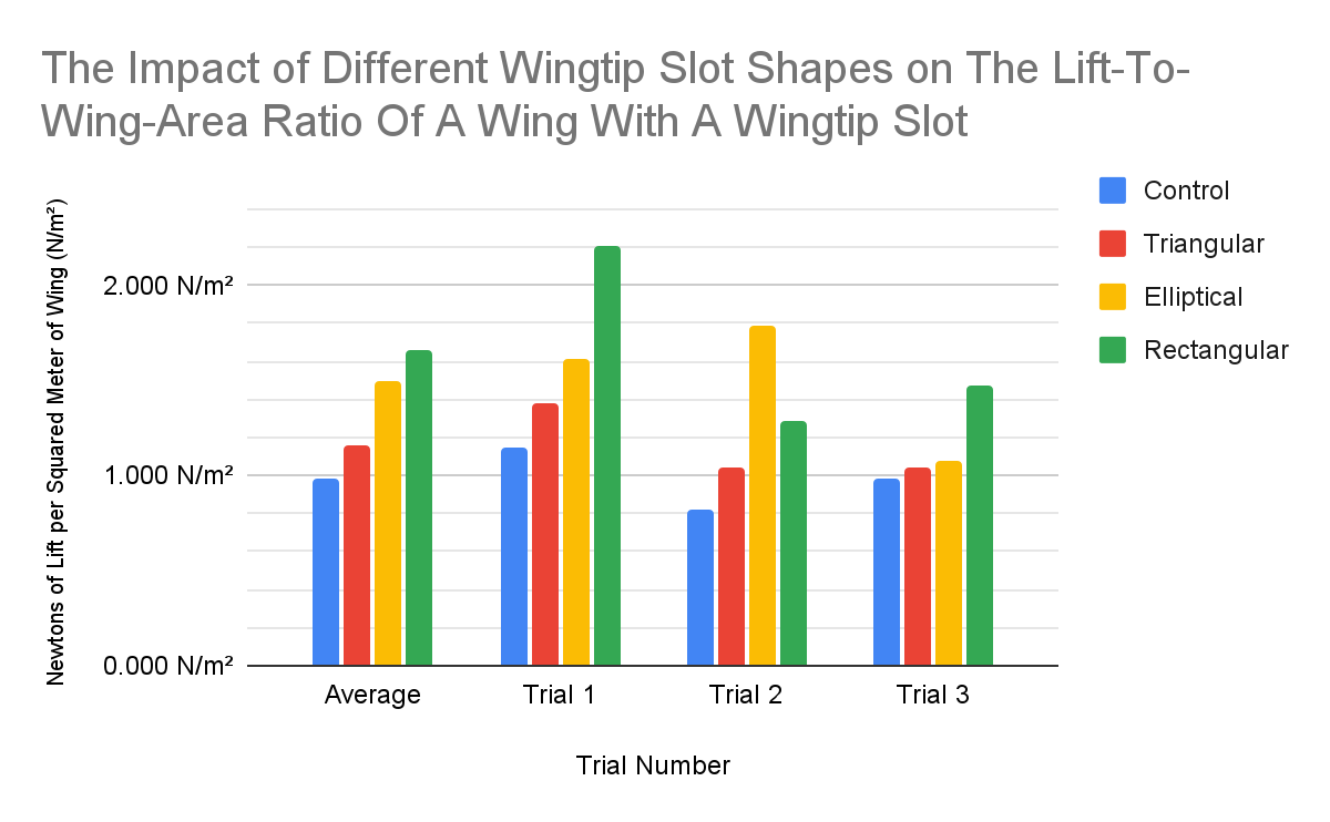
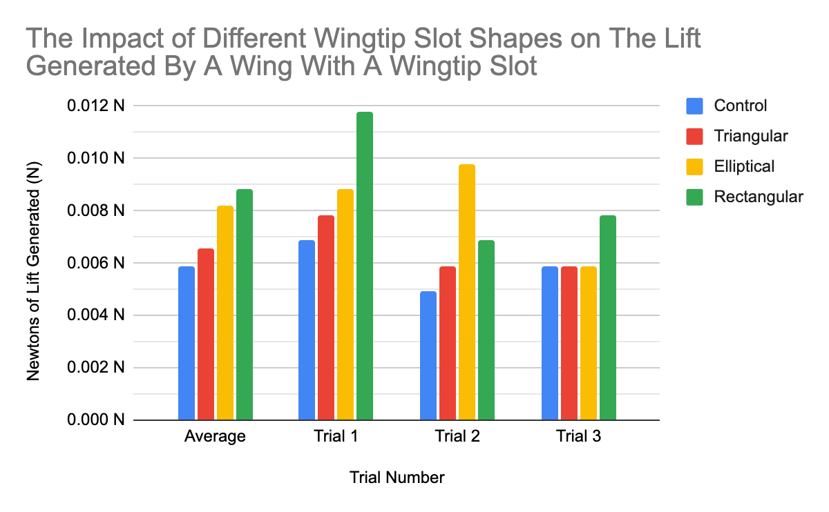
The Impact Of Differently Shaped Wingtip Slots On the Lift-To-Wing Area Ratio and the Lift Produced on a Wing With 1 Wingtip Slot
| Trial | Wingtip Slot Shape | Wing Area | Scale Reading (No Wind) | Scale Reading (With Wind) | Lift (In Newtons) | Lift (in Newtons) to Wing Area |
|
1 |
Control | 60.00 cm² | 0.70 g | 0.00 g | 0.007 N | 1.144 N/m² |
| Triangular | 56.67 cm² | 0.80 g | 0.00 g | 0.008 N | 1.384 N/m² | |
| Elliptical | 54.76 cm² | 0.40 g | -0.50 g | 0.009 N | 1.612 N/m² | |
| Rectangular | 53.33 cm² | 1.20 g | 0.00 g | 0.012 N | 2.206 N/m² | |
|
2 |
Control | 60.00 cm² | 0.00 g | -0.50 g | 0.005 N | 0.817 N/m² |
| Triangular | 56.67 cm² | 1.30 g | 0.70 g | 0.006 N | 1.038 N/m² | |
| Elliptical | 54.76 cm² | 1.50 g | 0.50 g | 0.010 N | 1.791 N/m² | |
| Rectangular | 53.33 cm² | 1.50 g | 0.80 g | 0.007 N | 1.287 N/m² | |
|
3 |
Control | 60.00 cm² | 0.00 g | -0.60 g | 0.006 N | 0.981 N/m² |
| Triangular | 56.67 cm² | 0.60 g | 0.00 g | 0.006 N | 1.038 N/m² | |
| Elliptical | 54.76 cm² | 0.00 g | -0.60 g | 0.006 N | 1.074 N/m² | |
| Rectangular | 53.33 cm² | 0.00 g | -0.80 g | 0.008 N | 1.471 N/m² | |
|
AVG |
Control | 60.00 cm² | 0.23 g | -0.37 g | 0.006 N | 0.981 N/m² |
| Triangular | 56.67 cm² | 0.90 g | 0.23 g | 0.007 N | 1.154 N/m² | |
| Elliptical | 54.76 cm² | 0.63 g | -0.20 g | 0.008 N | 1.492 N/m² | |
| Rectangular | 53.33 cm² | 0.90 g | 0.00 g | 0.009 N | 1.655 N/m² | |
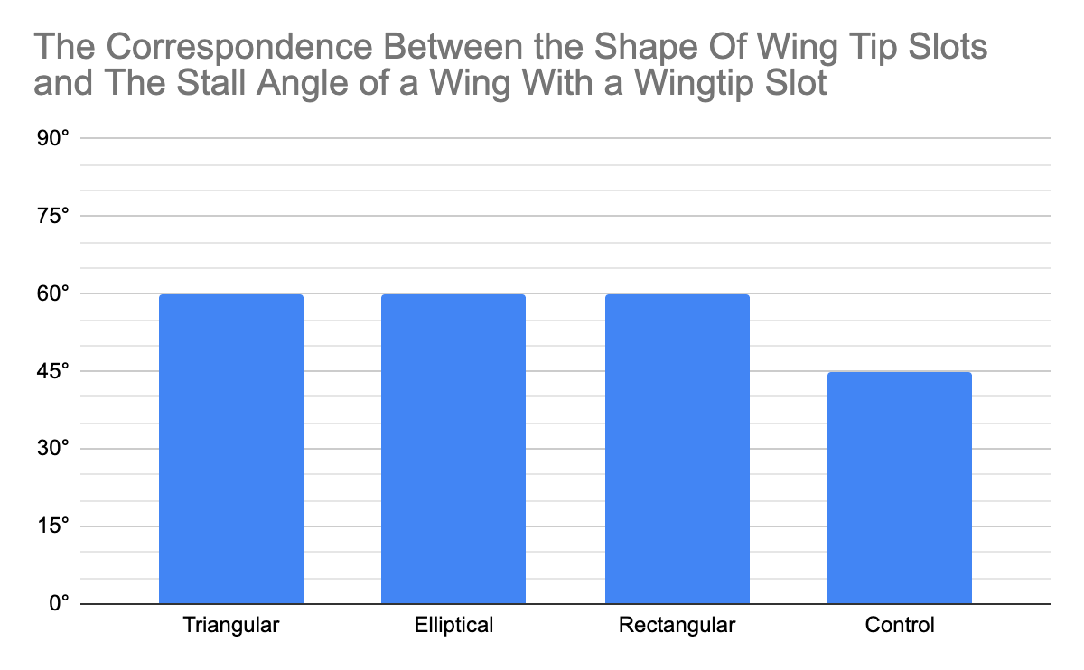
The Impact Of Different Wingtip Slot Shapes On the Stall Angle of a Wing With 1 Wingtip Slot
| Alula Angle | Stall Angle |
| Triangular | 60° |
| Elliptical | 60° |
| Rectangular | 60° |
| Control | 45° |
Analysis
Overall, the rectangular wingtip slot performed the best in both the lift produced and lift-to-wing-area ratio, followed by the wings with elliptical and triangular wingtip slots. The control wing performed the worst in all three areas. There was an outlier in trial 2, where the wing with a rectangular wingtip slot produced relatively much less lift than usual. This could be where the force transmitter disconnected, as I found it was broken at the end of trial 2, and may have affected other results. Other than in trial 2, the rectangular wingtip slot consistently performed better than all other wings. This is because the wingtip slot reduces the wingtip area, which prevents the formation of wingtip vortices and maintains the pressure differential. The square slot further increases lift, by using the flat base of the slot to generate wingtip vortices that push up on the trailing “feather”, creating a stronger high-pressure zone below it.
All wings with wingtip slots only stalled at 60°, compared to 45° for the control wing. This is because the leading “Feather” compresses air below it, which then is shot over the trailing “feather”, reinforcing the Coanda effect and preventing airflow separation.
Conclusion
Both my hypotheses were correct, as the wing with a rectangular wingtip slot performed the best in lift produced, lift-to-wing-area ratio, and stall angle. On average, the wing with a rectangular wingtip slot produces 1.5 times more lift than the control wing. This is because the rectangular shape of the wingtip slot and the reduced wingtip area reduce the loss of the pressure differential and harness some of the wingtip vortices for extra lift. The stall angle for all of the wings with wingtip slots was 60°, compared to 45° for the control wing. This is because the compression of air under the leading “feather” reinforces the Coanda effect over the second “Feather".
Iteration 6
Fine-tuning the size of the rectangular wingtip slot
Test Models
| Control |
0.5 cm Wingtip Slot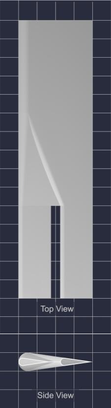 |
1.0 cm Wingtip Slot |
1.5 cm Wingtip Slot |
2.0 cm Wingtip Slot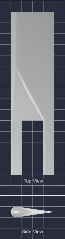 |
Hypothesis
If the square wingtip slot is 2 cm wide, then the lift and lift-to-wing area ratio will increase because the wingtip area would be greatly reduced by the slot and would reduce the generation of wingtip vortices, which will maintain the pressure differential and increase lift. Vortices generated by the flat base of the slot will be recaptured by the trailing “Feather” to further increase lift.
If a square wingtip slot is 0.5 cm wide, then the stall angle will increase, because the air will be compressed as it flows through the slot, resulting in a very high-pressure jet of air being shot along the whole trailing wing, reinforcing the Coanda effect.
Variables
Manipulated: Width of the wingtip slot (0.5cm, 1cm, 1.5cm, 2cm)
Responding:
- Lift to Wing Area ratio
- Lift Produced
- Stall Angle
Controlled:
- Basic Wing:
- Chord Length: 4cm
- Camber Length: 1cm
- Wing Span: 15 cm
- Wing cross section up until 5cm away from the wing root (Symmetrical)
- 1 wing tip slot
- Wingtip Slot
- Depth: 5 cm
- Shape: Rectangular
- Airflow in wind tunnel (Max)
Materials:
- Small wind tunnel with adjustable angle of attack and lift reading
- 3-D printed models of 4 identical airfoils with 1 wingtip slot with different wingtip slot widths(0.5cm, 1cm, 1.5cm, 2cm)
- 3-D printed model of control airfoil
- Cardboard spacer chip
Observations
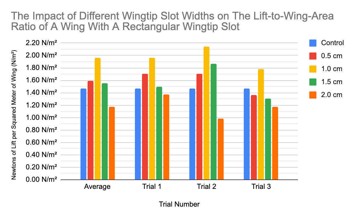
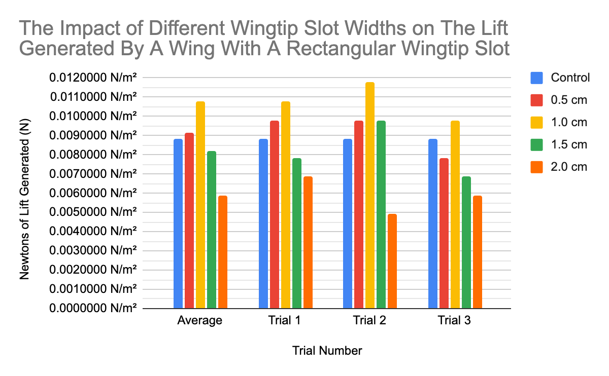
The Impact Of Different Wingtip Slot Widths On the Lift-To-Wing Area Ratio and the Lift Produced on a Wing With 1 Rectangular Wingtip Slot
| Trial | Wingtip Slot Width | Wing Area | Scale Reading (No Wind) | Scale Reading (With Wind) | Lift (In Newtons) | Lift (in Newtons) to Wing Area |
|
1 |
Control | 60.00 cm² | 0.90 g | 0.00 g | 0.009 N | 1.4709975 N/m² |
| 0.5 cm | 57.50 cm² | 1.00 g | 0.00 g | 0.010 N | 1.7055044 N/m² | |
| 1.0 cm | 55.00 cm² | 0.00 g | -1.10 g | 0.011 N | 1.9613300 N/m² | |
| 1.5 cm | 52.50 cm² | 0.00 g | -0.80 g | 0.008 N | 1.4943467 N/m² | |
| 2.0 cm | 50.00 cm² | 1.00 g | 0.30 g | 0.007 N | 1.3729310 N/m² | |
|
2 |
Control | 60.00 cm² | 2.00 g | 1.10 g | 0.009 N | 1.4709975 N/m² |
| 0.5 cm | 57.50 cm² | 1.30 g | 0.30 g | 0.010 N | 1.7055044 N/m² | |
| 1.0 cm | 55.00 cm² | 0.00 g | -1.20 g | 0.012 N | 2.1396327 N/m² | |
| 1.5 cm | 52.50 cm² | -0.50 g | -1.50 g | 0.010 N | 1.8679333 N/m² | |
| 2.0 cm | 50.00 cm² | 0.80 g | 0.30 g | 0.005 N | 0.9806650 N/m² | |
|
3 |
Control | 60.00 cm² | 0.00 g | -0.90 g | 0.009 N | 1.4709975 N/m² |
| 0.5 cm | 57.50 cm² | 1.80 g | 1.00 g | 0.008 N | 1.3644035 N/m² | |
| 1.0 cm | 55.00 cm² | 2.00 g | 1.00 g | 0.010 N | 1.7830273 N/m² | |
| 1.5 cm | 52.50 cm² | 0.00 g | -0.70 g | 0.007 N | 1.3075533 N/m² | |
| 2.0 cm | 50.00 cm² | -0.30 g | -0.90 g | 0.006 N | 1.1767980 N/m² | |
|
AVG |
Control | 60.00 cm² | 0.97 g | 0.07 g | 0.009 N | 1.4709975 N/m² |
| 0.5 cm | 57.50 cm² | 1.37 g | 0.43 g | 0.009 N | 1.5918041 N/m² | |
| 1.0 cm | 55.00 cm² | 0.67 g | -0.43 g | 0.011 N | 1.9613300 N/m² | |
| 1.5 cm | 52.50 cm² | -0.17 g | -1.00 g | 0.008 N | 1.5566111 N/m² | |
| 2.0 cm | 50.00 cm² | 0.50 g | -0.10 g | 0.006 N | 1.1767980 N/m² | |
The Impact Of Different Wingtip Slot Widths On the Stall Angle of a Wing With 1 Rectangular Wingtip Slot
| Alula Angle | Stall Angle |
| 0.5 cm | 75° |
| 1.0 cm | 75° |
| 1.5 cm | 60° |
| 2.0 cm | 60° |
| Control | 45° |
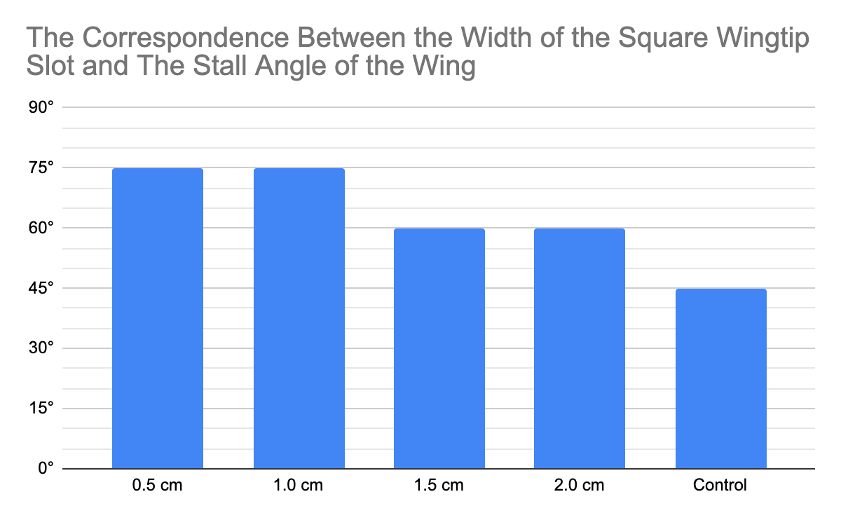
Analysis
The wing with a 1cm wide wingtip slot performed the best in both the lift and lift-to-wing-area tests. This is because the wings with larger wingtip slots basically became shorter, as they “Feathers” were not wide enough to perform as wings. This 0.5cm wingtip slot also didn’t work, as the slot didn’t effectively reduce the wingtip area. On average, All wings with wingtip slots except for the 2cm one performed better than the control, which meant that the 0.5 and 1.5cm wide wingtip slots still were effective.
The wings with 1cm and 0.5cm wingtip slots also performed the best in the stall angle tests, but the 1.5cm and 2cm wings still performed better than the control. This means that the smaller wingtip slots did compress the airstream, reinforcing the Coanda effect, but the larger wingtip slots also deflected air like normal, effectively decreasing the angle of attack of the trailing “feather”. The wing with the 1cm wide wingtip slot only stalls at 75°, but peaks at 0.024N of lift, so if the -20° alula was added, the peak lift might increase because most of the wing wouldn’t be stalled anymore.
Conclusion
Both my hypotheses were correct, as the wing with a 1cm wide wingtip slot generated the most lift and had the highest lift-to-wing-area ratio, and the 0.5cm wide wingtip slot had the highest stall angle. Overall, the wing with the 1cm wide wingtip slot performed the best, as it had the highest lift and stall angle of 75°, and will be used in all future tests.
Analysis
Over the whole project, the addition of avian adaptations have increased both the stall angle and the lift produced. This is most notable in iteration 6, where the addition of 1cm wide wingtip slots, increasing the lift by 133% and improving the stall angle from 45° to 75°. Over 60 million years of evolution have perfected these adaptations, allowing birds the agility and efficiency required in nature. I have yet to combine all my findings into a single wing to test, and expect to complete such test by April 11. For more information about each iteration, there are individual analyses for each trial
Sources Of Error
Due to my limited equipment, my homemade data collection system in the wind tunnel was not very consistent. This could be because of small changes in slider position, and inaccuracies in scale reading. I also was unable to perform more trials of the stall angle tests, as they were very tedious and took a long time to complete, but given more time I would have performed more trials
Conclusion
I have completed my objective, as the added bird adaptations greatly improved the lift, lift-to-wing-area ratio and stall angle of the wing. In iteration 4, the lift produced by the wing with bird adaptations was consistently around 27% higher than the control wing, which means that the bird wing could create more lift than the control wing could at the same speed. In addition, the bird wing only stalled and lost lift at a 75° angle of attack, while the control wing stalled at 45°. Just before stalling, the bird wing generated a peak lift of 0.024N, while the control wing only reached 0.016N. This amount of high lift and stall angle is useful for short landings, where the aircraft has to create enough lift to support its weight, but also is moving very slowly at a high angle of attack. In the latest iteration, a wing with added bird adaptations generated 33% more lift than the control, and also stalled at 75°. I have yet to test a combination of all my tests, but I expect the addition of alulea and winglets will further increase the stall angle and lift.
Extension
Before April 11, I will combine all the info I collected through my trials into one wing to compare to the control wing. Right now, the alula wouldn’t be suitable for high-speed aircraft, because of the air compression underneath the alula, which would make it very unstable. This could be solved by making the alula retractable, either manually or free-moving. The free-moving alula could work by usually being pressed down onto the wing by oncoming airflow, then being blown upwards when the wing reaches a certain angle of attack. I could also experiment with curving the wingtip, much like an elliptical wing, and adding differently sized and shaped wingtip slots, like those found in most elliptical winged birds. With access to more equipment, I would test high-speed wings, like those found on falcons, so this technology could be used for faster aircraft, but I don’t have access to equipment to generate sufficiently high windspeeds right now.
Applications
Many aircraft could use this technology, especially those that require capabilities similar to those of birds. Gliders could use raptor-like wings, which provide them with low vortex-induced drag and high lift, which are important while gliding at low speeds. Another application of this technology is for short takeoff and landing aircraft, such as bush planes. Alulea could be used to prevent stalling and increase lift at low speeds and high angles of attack, which are useful for taking off and landing with minimal runway. Commercial aircraft could benefit from both the increased stall angle and the increased lift, but this wing is currently not adapted for the high windspeeds that commercial aircraft operate at, and would require many more modifications before being accepted into this market. When adopted, this technology could reduce runway lengths, and increase fuel efficiency with increased lift. Alulea, being an external addition to the wing, could quickly be adopted as a post-market device, which can be quickly installed on existing aircraft without many modifications.
For further info, check out my Google Drive folder here.
Citations
Works Cited
Blain, Loz. “It’s a Bird... And a Plane? Africa’s Own Bizarre “NVTOL” Birdoplane.” New Atlas, 10 Dec. 2021, newatlas.com/aircraft/phractyl-macrobat-nvtol-africa/. Accessed 7 Oct. 2023.
Chin, Diana D., and David Lentink. “Birds Repurpose the Role of Drag and Lift to Take off and Land.” Nature Communications, vol. 10, no. 1, 25 Nov. 2019, www.nature.com/articles/s41467-019-13347-3, https://doi.org/10.1038/s41467-019-13347-3. Accessed 9 Nov. 2023.
“Closed Wing.” Wikipedia, 21 Apr. 2022, en.wikipedia.org/wiki/Closed_wing. Accessed 23 Dec. 2022.
Benjijart. “My Mini Wind Tunnel.” Www.youtube.com, 29 Dec. 2020, www.youtube.com/watch?v=ojo3pRilc1w.
Cornell Lab of Ornithology. Birds and Their Wing Shapes Activity Information Sheet.
Garrison, Peter. “Airfoils: A Short History.” FLYING Magazine, 25 Sept. 2009, www.flyingmag.com/technicalities-technicalities-short-history-airfoils/.
Harvey, C., et al. “Birds Can Transition between Stable and Unstable States via Wing Morphing.” Nature, vol. 603, no. 7902, 1 Mar. 2022, pp. 648–653, www.nature.com/articles/s41586-022-04477-8, https://doi.org/10.1038/s41586-022-04477-8. Accessed 7 Nov. 2022.
Lee, Sang-im, et al. “The Function of the Alula in Avian Flight.” Scientific Reports, vol. 5, no. 1, 7 May 2015, https://doi.org/10.1038/srep09914.
Robbins, Jim. The Wonder of Birds : What They Tell Us about Ourselves, the World, and a Better Future. New York, Spiegel & Grau, 2018.
Savile, D. B. O. “Adaptive Evolution in the Avian Wing.” Evolution, vol. 11, no. 2, 1957, pp. 212–224, www.jstor.org/stable/pdf/2406051.pdf?refreqid=excelsior%3Adb29cc87c58257a816ae86321f7fc1b1, https://doi.org/10.2307/2406051. Accessed 10 Oct. 2023.
Savile, D.B.O. “Bird Flight.” Www.thecanadianencyclopedia.ca, 6 Feb. 2006, www.thecanadianencyclopedia.ca/en/article/bird-flight#:~:text=Elliptical%20Wing. Accessed 1 Feb. 2024.
Sue. “How to Land (Gracefully) on a Stump.” Back Yard Biology, 26 Jan. 2017, bybio.wordpress.com/2017/01/26/how-to-land-gracefully-on-a-stump/. Accessed 1 Feb. 2024.
“The Nervous System and Senses.” Ornithology, 6 Jan. 2015, ornithology.com/ornithology-lectures/nervous-system-senses/#:~:text=In%20addition%2C%20the%20cerebrum%2C%20the. Accessed 1 Feb. 2024.
Tobalske, B.W., et al. “Kinematics of Flap-Bounding Flight in the Zebra Finch over a Wide Range of Speeds.” Journal of Experimental Biology, vol. 202, no. 13, 1 July 1999, pp. 1725–1739, https://doi.org/10.1242/jeb.202.13.1725. Accessed 11 Oct. 2023.
Tucker, V. A. “GLIDING BIRDS: REDUCTION of INDUCED DRAG by WING TIP SLOTS between the PRIMARY FEATHERS.” Journal of Experimental Biology, vol. 180, no. 1, 1 July 1993, pp. 285–310, journals.biologists.com/jeb/article/180/1/285/6536/GLIDING-BIRDS-REDUCTION-OF-INDUCED-DRAG-BY-WING, https://doi.org/10.1242/jeb.180.1.285. Accessed 14 Dec. 2023.
“Wake Turbulence.” Wikipedia, 21 May 2020, en.wikipedia.org/wiki/Wake_turbulence. Accessed 24 Dec. 2023.
Wikipedia Contributors. “Alula.” Wikipedia, 19 Nov. 2023, en.wikipedia.org/wiki/Alula. Accessed 4 Jan. 2024.
---. “Bird Anatomy.” Wikipedia, Wikimedia Foundation, 6 May 2019, en.wikipedia.org/wiki/Bird_anatomy. Accessed 19 Dec. 2022.
---. “Boeing X-53 Active Aeroelastic Wing.” Wikipedia, 12 Dec. 2023, en.wikipedia.org/wiki/Boeing_X-53_Active_Aeroelastic_Wing. Accessed 7 Jan. 2024.
---. “Eoalulavis.” Wikipedia, Wikimedia Foundation, 13 Oct. 2019, en.wikipedia.org/wiki/Eoalulavis. Accessed 12 Jan. 2023.
---. “Flap (Aeronautics).” Wikipedia, Wikimedia Foundation, 27 Sept. 2019, en.wikipedia.org/wiki/Flap_(aeronautics). Accessed 14 Jan. 2024.
---. “Leading-Edge Cuff.” Wikipedia, 17 June 2023, en.wikipedia.org/wiki/Leading-edge_cuff. Accessed 1 Feb. 2024.
---. “Wing Fence.” Wikipedia, 16 Mar. 2022, en.wikipedia.org/wiki/Wing_fence. Accessed 20 Jan. 2024.
---. “Wingtip Device.” Wikipedia, Wikimedia Foundation, 25 Sept. 2019, en.wikipedia.org/wiki/Wingtip_device. Accessed 19 Dec. 2023.
Zenith Air. “STOL Wing Design.” Www.zenithair.com, www.zenithair.com/stolch801/design-wing.html.
Acknowledgement
Many people helped me along the way with this project. Just a few people I’d like to thank are:
- My parents, for supporting me through the whole project
- Ivan Phillipsen, for answering some of my questions about bird evolution.
- Paul Gies, for answering my questions about the applicability of this technology in the current aviation industry.
- Mrs.Secord-Tomlin and Mrs.Davis, for guiding me through this project from a judge’s point of view.