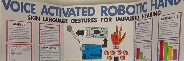
Voice Activated Robotic Hand - Sign Language Gestures for Impaired Hearing
Grade 9
Presentation
Problem
General Project Overview:
1.1 - Abstract:
For years, it has been exceedingly difficult to bridge the communication gap between people with impaired hearing and the rest of society. Often, sign language, such as American Sign Language (ASL) is used. Unfortunately, only a small percentage of the population can fluently converse in ASL. This project addresses the issue of the large communication gap between deaf people and the rest of society, through the design of a translation system. The goal of this project is to develop a robotic hand that implements the usage of real-time voice commands to translate spoken letters and words into American Sign Language hand gestures. This design was prototyped using the Arduino microcontroller, servo motors (with different torques), and the EasyVR 3 Plus speech recognition module. It was concluded that there was a 95% accuracy for the detection of “CANADA” in low noise environments, demonstrating the feasibility of the project. This innovation will continue to pave the way for future concepts for the benefit of hearing-impaired individuals.
1.2 – Introduction/Problem:
Hearing loss is a widespread problem affecting many individuals worldwide. It is referred to as the “reduced ability to hear sounds” [1]. Although it can be caused by a variety of things, it typically happens due to the factors of aging and prolonged exposure to loud noises often. In the United States, around one in every five people have hearing loss, or are deaf [2]. Loss of hearing, or impaired hearing, is becoming more prevalent over time, as the population increases. According to the World Health Organization (WHO), 42 million people were recorded to have disabling hearing loss during 1985. In 2018, that number rose to 466 million individuals. WHO predicts that by 2050, over 900 million people will have disabling hearing loss, which is around an eighth of the world’s total population. [3].
Unfortunately, members of the hard-of-hearing community face lots of struggles in day-to-day activities, as their inability to participate in conversation limits lots of their actions. For instance, the inability to hear can impact the number of opportunities they receive, due to the difficulty in communication. Job and education opportunities can be limited. There can also be more social withdrawal, leading to limited participation in most social activities [4]. On top of that, self-esteem can decrease, and there can be psychological and emotional factors that affect those deaf individuals. Have any measures been taken to ensure that deaf people can go to public presentations and understand what is being said? Is it possible for them to engage in conversation with strangers walking down the road? Can they go to the cinema and enjoy themselves watching a movie? Unfortunately, the answer is that most events are not accessible to people with extreme hearing loss.
Due to reduced ability to hear, clear communication with deaf patients is difficult, as only a small number of community members are educated in American Sign Language. Sign language is a format of visual communication, typically through hand gestures, used for communication with deaf individuals. In fact, there are around three hundred different sign language types around the world [5], but American Sign Language (ASL) is most used in North America. Sign language is based on the principle of associating meanings with different hand gestures. This is also known as fingerspelling, a generic term to describe the action of using hand signs to spell out letters.
The most used feature of ASL is the American Manual Alphabet (AMA), which is a system of twenty-six hand gestures, each representing a letter of the alphabet. These letters can be put together to spell words. Often, AMA is used just for the alphabet, but also for words that do not have a set sign. To form different letters, fingers are moved to various positions, and wrist movement can also be utilized. The combinations of finger and wrist movement form the 26 AMA letters. For this project, the AMA letters are used to sign words. For instance, if the word “CANADA” is spoken, then the following letters are signed: “C,” “A,” “N,” “A,” “D,” “A”.
1.3 - Research Questions:
There are very few innovations created for individuals with disabilities. Companies produce innovations and technologies based on their market size and ability to attract customers. Innovations for disabled individuals means that only people that are impacted by that disability may purchase the product. This means that the said product has a smaller market size, which means that fewer customers will be attracted to buy it. This product was derived from the inspiration to bring more innovations into the disability market.
One source of inspiration for this design came from the job of sign language interpreters. Obviously, sign language interpreters are used for only situations of extremely high importance, so not all speeches and presentations are inclusive, or even accessible for those that have impaired hearing. In fact, it is difficult for those that are hard-of-hearing to take part in day-to-day conversations as well, as only limited individuals can sign in ASL. Human-led tasks also have other issues, such as exhaustion over time. Sign language interpreters have limits to which they can do their job. This led to the question of: “How can we design an effective alternative to sign language interpreters, which can commonly be utilized?”
Another question was asked: “How can we design a human-like translation solution?” If a human-based approach is utilized, then it can be used more widely, and will be understood more easily. Instead of developing an application, which listens to what is said and translates it into ASL, a versatile solution should be implemented. These questions led to the idea of a robotic hand that imitates these sign language gestures, with the most focus on the AMA. This hand will ensure that any gestures signed will be clearly understood by those with impaired hearing.
Method
2 - Method:
2.1 - Goal:
As mentioned earlier, this project focuses on the development of a humanoid robotic hand, which answer to spoken voice commands to form hand gestures in American Sign Language (ASL). Any spoken letter of the alphabet can also be converted into ASL. The specific program created will be built in the Arduino IDE (Integrated Development Environment), and it will be focused on producing different finger movements for each letter of the American Manual Alphabet. There will be many humanoid hand prototypes and Arduino sketches before an efficient final design is reached.
The criteria of this project are as follows:
- Functionality of the hand (range of motion and speech recognition accuracy) – The robotic hand should be able to effectively detect each voice command, and make accurate hand gestures, relative to the actual gestures.
- Cost– This design should be an inexpensive solution, so that it can be considered a widely-accessible initiative and can be used in more communities for those that have impaired hearing.
- Durability – The robotic hand should not wear down overtime and maintain optimal performance over extended periods of use. It should not break down within a few months of use.
- Design and Aesthetics – It should look visually appealing, but this is the ultimate step in the project.
These criteria will be studied at the conclusion of the report to determine whether the final goal has been reached.
2.2 - Materials and Initial Hand Designs:
Materials (The ones with a star are the materials used in the final design.
- Arduino UNO microcontroller
- PCA9685 PWM Servo Driver
- Jumper wires
- Power supply module
- MG996R servo motors (6)
- EasyVR 3 Plus Speech Recognition Module from Fortebit
- 3D Printed Robotic Hand
- Sewing string
- Fishing line
- Cardboard
- Voice Recognition Module V3
- Miuzei SG90 Micro Servo motors
- KidzLab Robotic Hand
- Ballpoint pen springs
- Dynamic Microphone
- 3D Printed Robotic Hand
2.2.1 – Cardboard Hand + Plastic Hand:
The “Straw Cardboard Hand” model was a preliminary design, used to assess the potential issues in this project. For this, a cardboard outline was cut out, and five measured straw pieces were glued onto the cardboard base. Sewing string was threaded through the hole in each servo motor’s rotational arm. When the command was given, the servo motor would pull the rope and close the straw finger. Figure 2.1 is an image of the preliminary cardboard robotic hand.
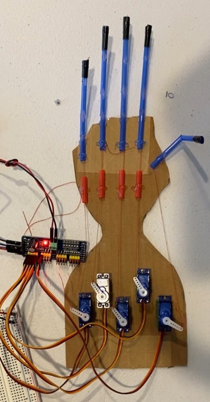
Figure 2.2.1.1 – Image of the Straw Cardboard Hand Design
The criteria of this design were not met in a satisfactory manner. The robotic hand was not functional and had no range of motion, as there was no control to determine the angle at which the fingers would remain at. However, the hand was very inexpensive. The fingers, as well as the palm of the hand, were not durable. It was visibly seen that the creases where each finger bent were slowly starting to tear. Lastly, the design was not acceptable, as there was more potential for a professional finish to enhance the project.
The next robotic hand design was a larger, 3D hand. This hand perfectly imitated a human hand, as it had movable joints, as well as fingers that resembled human fingers. There was trial and error, as well as designing and redesigning of the moveable parts. Figure 2.2 is an image representing the template that was used to make each cardboard finger.
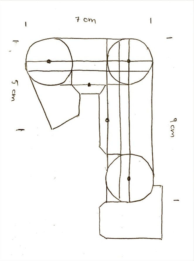
Figure 2.2.1.2 – Cardboard Finger Template
representing the template used to cut out cardboard parts to form each finger. This was an extremely time-consuming process, as many parts turned out to be damaged in shape. All the cut-outs were hot glued together to form each individual finger.
Each 3D finger had two joints to bend, and a cardboard strip was glued to the back of each joint to prevent the fingers from bending backwards. Afterwards, each finger was connected to a 3D hand palm. A fishing line was glued to the top of the finger, and the bottom of the fishing line was connected to the servo rotational arm. When the servo moved away from 0 degrees, the fishing line would get pulled, which allowed the finger to close to the 180-degree position. The question
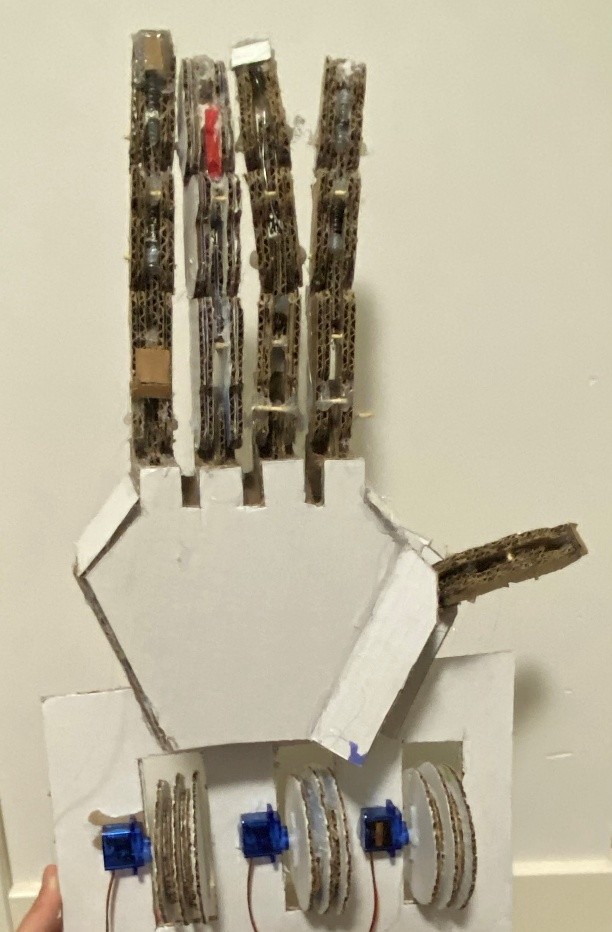
Figure 2.2.1.3 – Full 3D Cardboard Robotic Hand
arises as to how the finger can be brought back to 0 degrees from 180 degrees. This motion is referred to as the “snap back” motion in this project. Initially, a rubber band was glued to the back of the finger to create tension at the back, ensuring that the finger would snap back into 0 degrees once the servo released its tension and went back to the open state. Although the rubber band idea did work, a rubber band alone was not strong enough to bring each finger fully back to the open position. Elastics with varying levels of tension were tested, such as rubber bands, and many different elastic waistbands, taken out of stretchy pants and shorts. After several trials, it became clear that elastics were not suitable for a large hand such as the one shown in Figure 2.3. Additionally, elastics were not an ideal solution, as they would not fit in with the durability criteria. Over time, elastics typically lose their original tension, meaning that the fingers would not snap back to 0 degrees.
Since elastics were no longer a viable option for the snap back motion, a pulley system was developed. This time, there were two separate fishing lines involved. The front fishing line was glued to one side of the pulley, inside the indentation, while the other fishing line was glued onto the other side of the pulley, 180 degrees from the first fishing line. Each pulley was attached to the movable arm of each servo motor. This meant that when the servo rotated, so would the pulley, and the fishing lines would also get impacted. Often, pulleys are used in robotics to allow strings to smoothly move and bend. However, pulleys are utilized in this large robotic hand to increase the distance the fishing line could be pulled to snap the finger closed. If the fishing line was directly connected to the smaller arms of the servo motor, then a 180-degree rotation would not be sufficient to put the finger in a closed position. For the finger to go from an open to closed position, the fishing line needed to be pulled approximately 9.2 centimeters in total. If we assume c = circumference of the pulley and r = radius of the pulley, then c2=9.2 cm and c=18.4 cm. Assume that π = 3.14. To solve for r:
c = 2πr
18.4 = 2(3.14)r
r = 2.93 cm
The radius of the pulleys needed to be 2.93 cm to ensure that the fishing like would be pulled 9.2 cm when the servo motor moves 180 degrees. For instance, if the servo moved to the closed position, then the pulley would turn 180 degrees, pulling the front fishing line taut while the back fishing line would loosen. This allowed the entire finger to snap closed. To bring the finger back to the open position, the servo motor would be moved to 0 degrees, which loosened the front fishing line but pulled the back line tight. This ensured that the finger stayed upright in an open position. However, this example was only a theoretical assumption of how this pulley system would work. Not long after, it was determined that the back of the finger had to move the fishing line a farther distance than the front line to bend 180 degrees. The distance the back fishing line moved for the finger to close was 10.5 cm, compared to the front line, which was 9.2 cm. The same calculations were done, knowing that c2=10.5 cm, and therefore c=21 cm.
c = 2πr
21 = 23.14r
r = 3.34 cm
To ensure that both the front and back fishing lines would move 9.2 cm and 10.5 cm respectively, a double pulley system was created, where two pulleys with different circumferences were adjacently glued together as one pulley system, shown in Figure 2.4 below. The servo motor driving the system would be able to move both pulleys simultaneously, satisfying the needs of both fishing lines. This worked quite well! However, during the development of this cardboard hand, the wear and tear of the hand was extremely noticeable over time. Since it was made primarily using cardboard, joints were becoming loose, and pulleys were also beginning to fall apart. Due to this, it was clear that this robotic hand did not meet the durability criteria. A new robotic hand was developed.
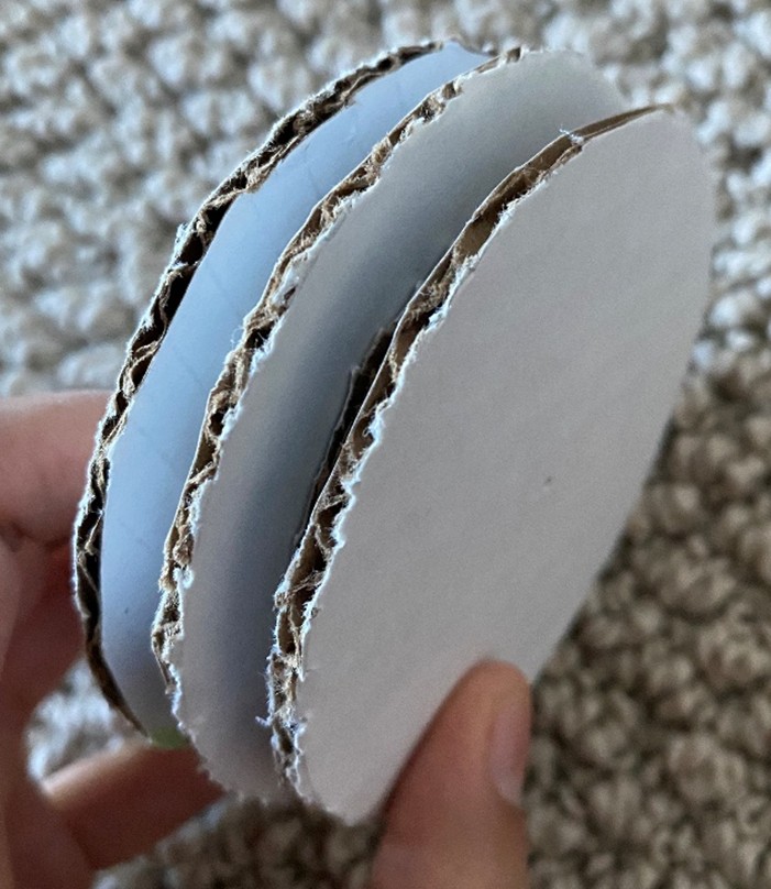
Figure 2.4 – Double pulley system
Trial 2 – Plastic Robotic Hand:
Since the goal was to create a functional, durable hand, it was decided that plastic would be a suitable alternative to cardboard. A plastic hand, smaller than the cardboard one, was incorporated into this project, shown in Figure 2.5. Since plastic tends to go back to its original tension, there was no need for a snap-back motion. However, each plastic finger will obviously lose their tension over time, so rubber elastics were added to the backs of each finger to ensure that the fingers will always snap-back. The plastic hand was glued to a shoe box, and each servo was organized on the shoe box. Just like the other robotic hands, the fingers would bend when the servo started to move. This hand did not require pulleys, since the distance the fingers needed to move to go from 0 to 180 degrees was the same as the distance the servos are able to move. After testing, it was determined that this simple robotic hand works very well.
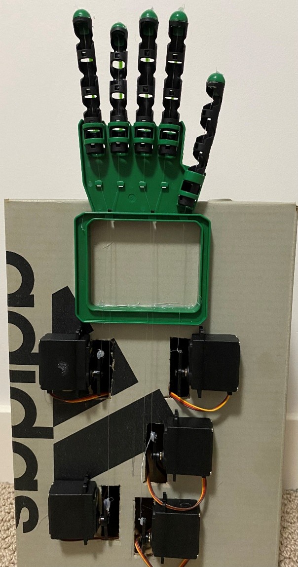
Figure 2.2.1.4 – Plastic Robotic Hand
Certain letters of the ASL alphabet require wrist movement. For instance, the letter “C” requires the wrist to turn 90 degrees. However, this plastic robotic hand does not have a moveable wrist joint. For this reason, a new robotic hand is required.
2.2.2 - Final Developed Robotic Hand:
The goal of this 3D printed robotic hand was to produce a hand with a moveable wrist joint. Letters such as “C,” “D,” and “F” require some degree of wrist capability. To do this, a 3D printed robotic hand was incorporated into this project. A high torque servo motor (MG 996R) was glued to the base of the 3D printed robotic hand, allowing for wrist motion between 0 and 180 degrees. The 90-degree position is the neutral position for the hand. Figure 2.2.2.1 is a representation of how the 3D printed hand works. This hand is the final product.
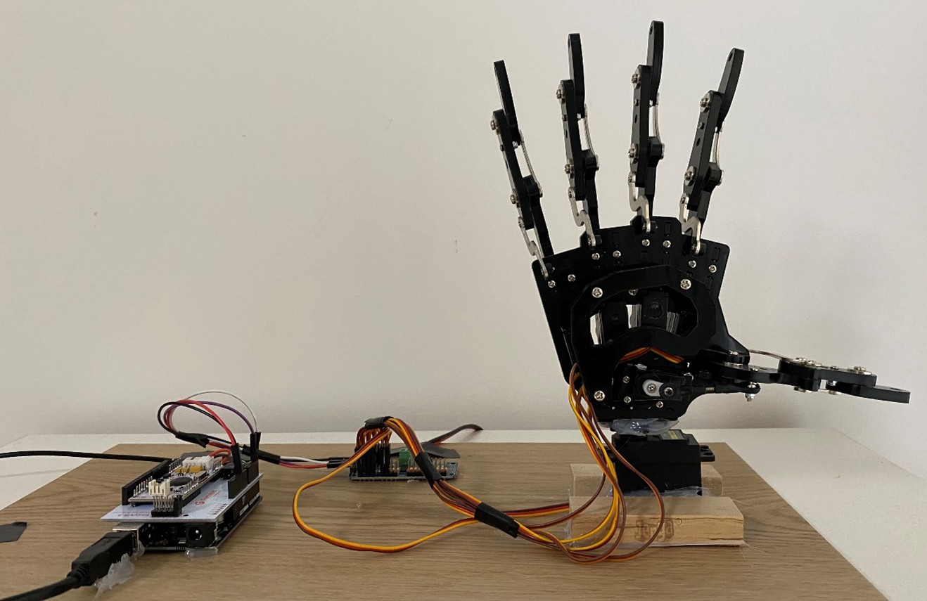
Figure 2.2.2.1 – 3D Printed Robotic Hand System
2.3 - Speech Recognition Design + Program:
The robotic hands were not the only challenge that this project was faced with. There were many voice recognition modules available on the market with different recognition capabilities. The purpose of voice recognition modules is to store commands and be able to detect when a trained command is spoken. This way, any microcontroller connected to the module (in this case, the Arduino) would be able to associate an action with the detection of that specific command.
Typically, voice commands can be divided into two groups when it comes to voice recognition. There are Speaker Dependent (SD) and Speaker Independent (SI) voice commands. They are simply two separate groups in which voice commands are detected. SD commands refer to trained commands that can only recognize the speaker that trained the command. This means that the command will not be recognized by the module if other people say it. SI systems are trained to be able to recognize a trained command regardless of who says it. However, both systems have their drawbacks. SD commands can only be effective for the person who trained those commands. On the other hand, SI commands may potentially be less accurate.
2.3.1- Voice Recognition Module V3:
The first module that was used was the ELECHOUSE “Voice Recognition Module V3”, shown in Figure 2.3.1.1 below. This Speaker Dependent module was approximately fifty dollars to purchase from Amazon. In previous ELECHOUSE voice recognition module versions, such as the “Voice Recognition
Module V2,” all voice commands would be separated into three groups. Each group could only support five commands maximum. This meant that the V2 was capable of only holding fifteen commands in total, while only one group could be active at once to be recognized.
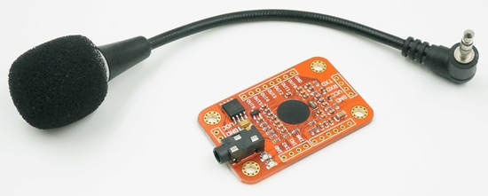
Figure 2.3.1.1 [9] – Voice Recognition Module V3 (Version 3)
On the other hand, the Voice Recognition Module V3 is much more advanced. In total, the V3 can store eighty voice commands as opposed to just fifteen. Additionally, instead of having multiple smaller groups, the V3 has one large group to store all commands. While the V2 may only have five active commands, the V3 can have seven. A microphone was also supplied with this module, and the microphone could be plugged into the audio jack to receive audio input. Overall, the Voice Recognition Module V3 was not satisfactory, as the module’s voice recognition system was not perfectly accurate. Some testing revealed that in low noise environments, the module could only recognize one command out of twenty, which means it had a 5% accuracy in low noise settings.
2.3.2– EasyVR 3 Plus:
Since the Voice Recognition Module V3 had ineffective voice recognition, new modules were searched for. Finally, the “EasyVR 3 Plus” by Fortebit was bought with an EasyVR 3 Plus Shield board, shown in Figure 2.3.2.1 below. This module also had previous versions, such as the “EasyVR 3.” In general, the EasyVR 3 Plus had many more advanced capabilities over the Voice Recognition Module V3. It had a total storage capacity of 256 Speaker Dependant voice commands, much larger than the eighty total commands in the V3. Each of the groups can hold thirty-two commands, which means that thirty-two out of 256 commands can be active at once. Thirty-two commands are more than four times the number of commands the V3 can have active. However, there was one main question remaining: Is the EasyVR 3 Plus accurate? The accuracy of voice recognition was remarkably high, as it typically was able to detect most commands. However, the accuracy mostly is dependent on the type of microphone being plugged into the module: condenser microphones or dynamic microphones. The results are explored in the ‘Analysis’ section. The EasyVR 3 Plus was a little different from the V3 because it utilized an Easy VR 3 Plus Shield. In Figure 2.3.2.1, the EasyVR 3 Plus is mounted atop a larger board, which is known as a “shield” board. The shield is like a daughterboard. Essentially, the shield is placed on
top of the Arduino as an “add-on” circuit board that also adds more functionality [11].
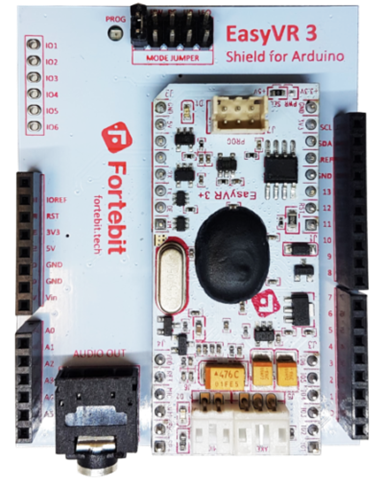
Figure 2.3.2.1 [10] – EasyVR 3 Plus Module + Shield
The EasyVR 3 Plus was trained through the EasyVR commander, an application where the commands are trained using a connected microphone. Figure 2.3.2.2 shows how the EasyVR Commander looked. All the trained word commands are in Group 2, while the trained letters are in Group 1. The EasyVR Commander made the training process easier, as it helped structure the system.
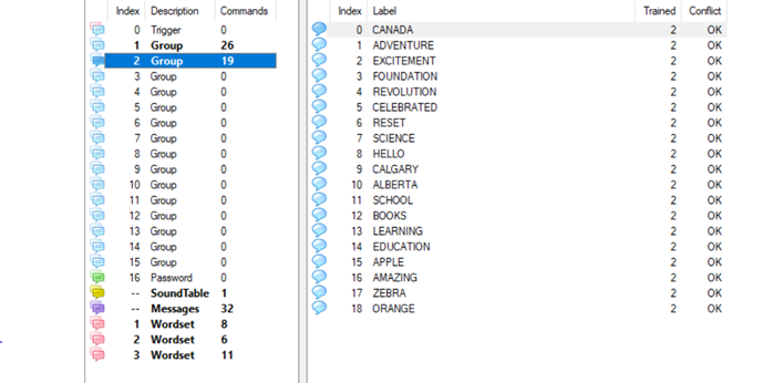
Figure 2.3.2.2 – EasyVR Commander
Final Product:
After many trials and redesigning of components, the final product is created. The robotic hand uses six servo motors. One servo motor operates each finger, and one servo operates the wrist joint. Each of the six servos are plugged into the PCA9685 servo driver, and the servo driver is connected to the Arduino pins. An external power source is powering all the servo motors. The EasyVR 3 Plus is used for the voice recognition within the system. The EasyVR 3 Plus is connected to a shield, and the shield is joined to the Arduino microcontroller. Then, a microphone is connected to the EasyVR 3 Plus. A spoken command input is taken through the microphone and changed into the output of moving the servo motors to certain angles, which forms one letter.
Groups of those letters create one word! Figure 2.3.2.3 represents the final product.
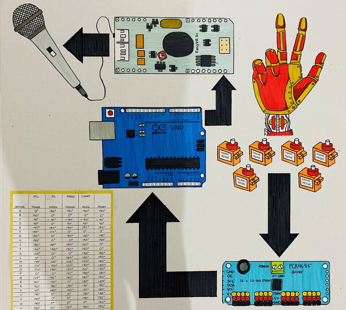
Figure 2.3.2.3 – Full process + Final product
3 - Technical Explanation:
Servo Motors:
Servo motors (servos) are used in this project to move each finger. Servo motors fall into the category of electric motors. Typically used in robotics, servos are used for precision, as they allow users to accurately control direction of rotation and degree of rotation. Figure 3.1 shows how a typical micro servo motor looks. Servos fall into two categories: Continuous servos and positional servos. Continuous servos allow servo motors to rotate 360 degrees. Positional servos restrict movement to 180 degrees, typically through the usage of a pin to prevent rotation past 180 degrees. However, this project only utilizes positional servos.
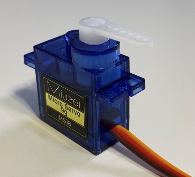
Figure 3.1 – Image of Micro Servo Motor
Servo motors rotate due to the fundamental concept of pulse width modulation (PWM). PWM is a type of direct current signal. Direct current, known as DC, is a form of current that has only two states only. This can be “high” or “low,” and “on” or “off.” A typical direct current signal is shown in Figure 3.2. DC sources allow current to move in only one direction. PWM is utilized by servos to change the duration of how long a DC signal is high (on) for.
The duration that a servo’s PWM signal is on for determines the direction of rotation for the motor, a well as the degree of rotation. A “pulse” defines the duration that a signal is high, or on for. Wider pulses tell the servo to move towards 180 degrees, while smaller pulses tell it to move towards 0 degrees. All servo motors have a neutral position, which is defined as the center of rotation. For positional servos, the center of rotation is 90 degrees. A cycle refers to the total period when the pulse is high (on) and low (off). Most servo motors, such as SG90 servos have a frequency of 50 Hz, or 50 cycles per second. This means that each cycle is 20 milliseconds long. Within 20 milliseconds, the width of the pulse determines the
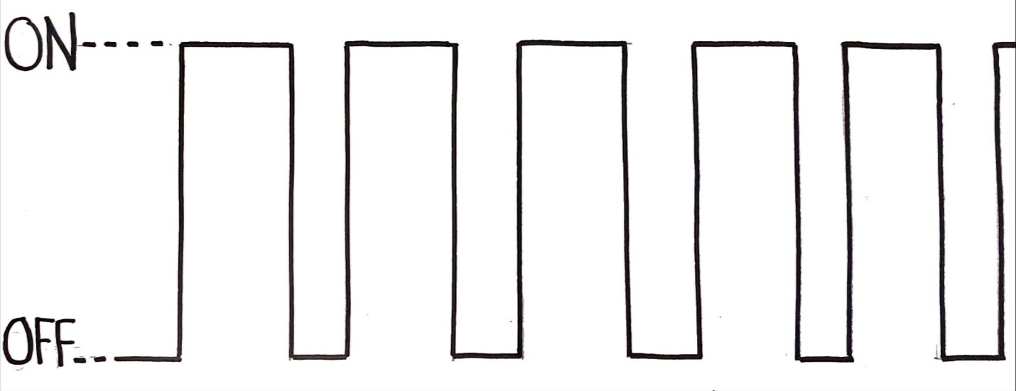
Figure 3.2 – Example of a DC signal
angle the servo moves to. Figure 3.3 is a chart that represents the duration a cycle should be on and off for different angles (in an SG90 micro servo motor). 1 millisecond represents the minimum width of a pulse, and 2 milliseconds represents the maximum. Any value in between will move the servo motor to an angle in between 0 and 180 degrees. Duty cycle is a measurement, in percentage, of the total time the signal is high in a full cycle. For instance, a pulse width of 2 milliseconds would have a duty cycle of 10%. This is because 2 milliseconds out of 20 milliseconds is 10% of the full cycle. In this case, 2 milliseconds would be the pulse width, or the time the cycle is high. 18 milliseconds would be the time that the signal is off.
|
Position/Angle |
Pulse Width (High/On) |
Signal Duration (Low/Off) |
Duty Cycle (%) |
|
0 degrees |
1.0 millisecond |
19.0 milliseconds |
5% |
|
90 degrees |
1.5 milliseconds |
18.5 milliseconds |
7.5% |
|
180 degrees |
2.0 milliseconds |
18.0 milliseconds |
10% |
Figure 3.3 – SG90 Servo Pulse Width Guide
Servo motors have a variety of components that allow them to precisely rotate. All the primary components are shown in Figure 3.4 below:
DC Motors - A crucial component of the servo motor is the DC motor. DC motors operate on the principal of electromagnetism, which is defined as the relationship between electricity and magnetism. DC motors harness DC current from a source, such as a battery and convert it into mechanical rotation. Once a DC input is taken, the electrical current passes through the rotating coil within the motor. This produces a rotating electromagnet, known as a rotor. A stationary field magnet (stator) is positioned around the rotor. Due to the attracting and repelling forces between the rotor and stator, mechanical energy is produced! In a servo motor, the DC motor performs the rotation
.
Gear Train – The gear train is a chain of gears that are driven by the DC motor. The input gear starts off with a high speed but low torque. The output gear (final gear in train) has a low speed but high torque. Different sized servos have different torques, due to the varying voltages and gear trains.
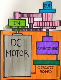
Figure 3.4 – Internal Components of a Servo Motor
within them. For instance, an SG90 servo has a stall torque between 1.3 kg/cm to 1.5 kg/cm [7]. Kilograms per centimeter is the unit of measurement for torque. It represents how many kilograms of mass the servo can carry one centimeter away from the shaft.
Circuit Board - Dc motors, when receiving voltage from a power source, instantly move. On the other hand, servo motors, when provided with a voltage, do not move. Servo motors will not operate without a microcontroller or control board providing a PWM signal, such as Arduino or Raspberry Pi. The circuit board is a principal component of the servo motor. It works by receiving the specific PWM signal from the microcontroller, and it converts it into an action to control the servo output. Typically, the circuit board ensures that the instructions passed down by the controller are conducted. A critical part of the circuit board is its feedback loop- a system in which the output is used to improve the input [8]. This allows for adaptation and minimal errors within the servo system. For instance, if the servo does not move to the right position, that position is sent back to the circuit board. Then the circuit board uses that output position to tell the motor where to move to reach the correct position.
PCA9685 Servo Driver:
The PCA9685 is a 16-channel Pulse Width Modulation Driver, shown in Figure 3.5. This is used to control up to sixteen servo motors using one board. Typically, an Arduino itself does not have enough pins to individually control each servo motor, which is why the PCA9685 is used. This servo driver allows for minimal Arduino pins to be occupied, while still using a large quantity
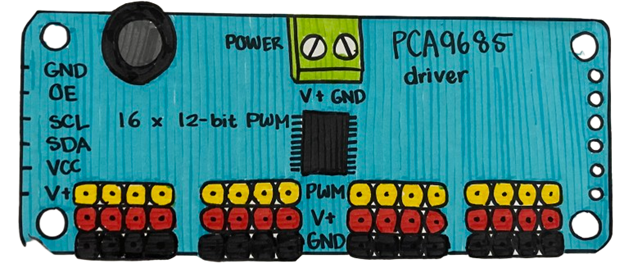
Figure 3.5 – PCA9685 16-channel Servo Driver
of servo motors. Power can also be supplied to all the servo motors through an external power source. In this project, an extern
al adapter was utilized.
Arduino:
Arduino is a platform that is widely used to construct electrical projects. “Arduino” refers to both the Arduino microcontroller and the Arduino Integrated Development Environment (IDE) to program the board. The Arduino microcontroller is one of the main components of all the robotic hands shown previously. Figure 3.6 is a representation of the Arduino board. There are many diverse types of Arduino boards, which all work similarly but have different capabilities. This project utilizes the Arduino Uno. The microcontroller is the device that executes an action after a command has been detected by the EasyVR 3 Plus voice recognition module. Essentially, the Arduino takes in an input and changes it to an output. In this case, the input is the spoken command, and the output is the movement of the servo motors to form different ASL hand gestures. Keep in mind that the following components are specific to the Arduino Uno microcontroller and may not be the same as other Arduino boards.
ATmega328P = The Arduino board carries a highly efficient critical component, known as the ATmega328P microcontroller. The ATmega328P is responsible for storing the program, executing it, and controlling all the input and output operations. The program gets stored in the ATmega328P’s flash memory- a type of storage strategy where the program gets retained even
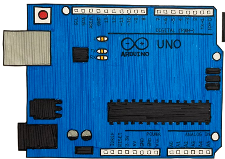
Figure 3.6 – Arduino Microcontroller
when you turn off the Arduino. You can also erase the flash memory and reprogram it [14]. The flash memory allows for new programs to be created.
Digital and Analog Pins – On the Arduino Uno board, there are visible pins running along the sides. These can be divided into two categories: digital and analog pins. Digital pins can read digital inputs and power digital outputs. Digital pins power digital outputs using two voltage levels: “HIGH” (on) and “LOW” (off). Since digital pins use DC to power outputs, there are always two states. “HIGH” may represent five volts, while “LOW” may represent 0 volts. For instance, a digital input may be a switch. There are only two states on the switch: on or off. Then, the state of the switch may be used to power a digital output, such as a simple LED. When the switch is on, the digital signal is “HIGH,” which means that the full 5V is powering the LED. When the switch is off, then the digital signal is “LOW,” meaning that there is 0V powering the LED, turning it off. On the other hand, the Arduino analog pins can read analog inputs. They read various levels of voltages between 0 volts and 5 volts. For instance, a potentiometer, also known as a variable resistor, can be considered an analog input. This is because it has multiple states, not just two.
USB Connector – The USB (Universal Serial Bus) connector establishes the connection between the Arduino board and the IDE. The USB can be used to provide power for the microcontroller, but it also allows the program to be stored in the ATmega328P.
Power Port – The power port is an alternative to powering the Arduino. When the USB is not being utilized, or when the program is already stored within the ATmega328P, an external power source can be used to power the board through the power port.
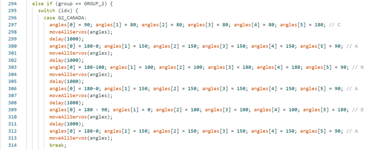
Figure 3.7 – “CANADA” code in Arduino IDE
Figure 3.7 is a picture of the code used in the Arduino IDE to program what is happening to the output – servo motors – when the command “CANADA” is detected by the EasyVR 3 Plus module. Figure 3.7 is representing a switch-case statement. In Arduino, switch-case statements allow the execution of different blocks of code depending on the value of the variable. In this case, the variable is “idx,” and it is referring to all the spoken commands. If we look at case “G2_CANADA,” the code below says that if “CANADA” is detected as the idx by the EasyVR 3 Plus, then each of the six servos (including the wrist servo) will move to a certain angle. If "G2_CANADA" command is not detected, then it moves on to the next command in the switch-case statement to check if that one is detected.
Microphones:
Microphones are devices that convert audio/sound waves into electrical signals [12]. In this project, trained voice commands are said into a microphone as a first step. As mentioned earlier, there are two main types of microphones utilized in this project: condenser microphones and dynamic microphones.
Condenser Microphones – These are extremely sensitive microphones. Condenser microphones notice even the smallest noise. They are preferred when the application requires a microphone to convert the smallest and quietest noise [12].
Dynamic Microphones – Dynamic microphones are less sensitive compared to condenser microphones. More importantly, they are preferred for applications where there is constant “ambient noise.” Ambient noise refers to continuous background noise [13]. Dynamic microphones were perfect for this project since they are less sensitive to ambient noise. That means that this robotic hand can be utilized in larger, more crowded areas. If this robotic hand is being used in a large speaker presentation, it should be able to ignore crowd noise and only focus on the speaker.
Analysis
4 – Analysis:
The final robotic hand product decreases in accuracy when the noise in the environment increases. This means that the accuracy is inversely proportional to the noise. However, testing shows that there are various levels of accuracy when the microphone connected to the EasyVR 3 Plus is changed. As discussed previously, there are condenser microphones and dynamic microphones. Figure 4.1 is a bar graph displaying the accuracy of the module’s voice recognition in varying noise environments when a condenser microphone is used.
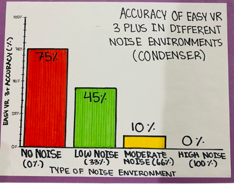
Figure 4.1 - Accuracy of EasyVR 3 Plus in Different Noise Environments (Condenser)
The noise percentages (0%, 33%, 66%, 100%) represent the volume percentage on TV when crowd noise is being played. It is clear from the graph that the accuracy is extremely low, especially as noise gets louder. When the microphone was switched out with a dynamic microphone, there were completely different results. Figure 4.2 is a similar bar graph representing the accuracy of the EasyVR 3 Plus in different noise environments. However, Figure 4.2 is representing the accuracy when a dynamic microphone is connected to the voice recognition module. As mentioned earlier, dynamic microphones are less sensitive to ambient noise, which is why they show better results than condenser microphones.
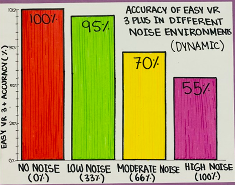
Figure 4.2 – Accuracy of EasyVR 3 Plus in Different Noise Environments (Dynamic)
The final voice controlled robotic hand reached the criteria defined at the beginning of the project. The entire system cost around 250 dollars, which is very inexpensive. The functionality and motion are great, as the hand signs accurately mimic a human hand. The angles to sign conversion were correct. Lastly, the design was strong and durable. Previous hand models did not have the durability factor, but the final product is capable of lasting for a long time.
Conclusion
5 - Conclusion:
This project focused on the development of a solution to provide support to individuals with hearing impairment in society. The solution was a robotic hand with a voice recognition system that translated spoken letters and words into American Sign Language hand gestures. This will allow the minority of people with hearing impairment to now take part in daily activities, such as attending school, listening to conferences and meetings, speaking to friends, and even watching movies! The robotic hand is an accessible initiative for everyone! This revolutionary, innovative solution now shows how technology can be deployed for the betterment of society.
There are existing phone applications that address this issue. However, during many tests and trials of these apps, it was determined that they do not provide accurate visualization of words to ASL gestures. Additionally, the idea of an app solution is not scalable. For instance, in large presentations, it is not effective to use a phone app to convert the speaker’s voice into sign language. On the other hand, a robotic hand can be used in the same way as a sign language interpreter!
Not only that, but there are a few limitations to this voice activated robotic hand. For letter recognition, letters such as C, B, D, E, G, P, T, and V all sound very similar, which often leads to confusion within the voice recognition module. The module is less accurate at classifying between these letters. In noisier environments, the voice recognition module’s accuracy decreases. Another limitation is that only trained words can be recognized, which leads back to machine learning. If a machine learning solution could be utilized to detect individual letters within any spoken word, then this product could understand all words! This voice activated robotic hand is a revolutionary project and a beneficial solution for humankind.
There are many improvements for this robotic hand. Instead of servo motors, stepper motors would allow for better hand movements and more wrist freedom. Additionally, adding more motors in each finger and the wrist would allow for more precise hand gestures. Most importantly, a machine learning model can be deployed to be able to detect all words and letters, improving the overall capability of the robotic hand to detect voice commands. A Speaker Independent (SI) machine learning model would allow the model to be able to understand all voice types and languages, advancing the product!
Citations
Report Citations:
-
Hearing Loss | HealthLink BC. www.healthlinkbc.ca/healthwise/hearing-loss.
- Abou-Abdallah, Michel, and Abigail Lamyman. “Exploring Communication Difficulties With Deaf Patients.” Clinical Medicine, vol. 21, no. 4, June 2021, pp. e380–83, doi:10.7861/clinmed.2021-0111.
- Davis, Adrian C., and Howard J. Hoffman. “Hearing Loss: Rising Prevalence and Impact.” Bulletin of the World Health Organization, vol. 97, no. 10, Sept. 2019, pp. 646-646A, doi:10.2471/blt.19.224683.
- Department of Health & Human Services. “Hearing Loss - How It Affects People.” Better Health Channel, www.betterhealth.vic.gov.au/health/conditionsandtreatments/hearing-loss-how-it-affects-people. Accessed 20 Mar. 2025.
- Sign Language. education.nationalgeographic.org/resource/sign-language. Accessed 20 Mar. 2025.
- Henson, Mark. “A Guide to Electric Motors.” Dietz Electric Co., Inc., 27 June 2024, www.dietzelectric.com/blog/guide-to-electric-motors/#:~:text=The%20electric%20motor%20is%20one,conveyor%20belts%2C%20and%20power%20tools.
- “SG90 Micro Servo Motor Price TowerPro | JSumo.” https://www.jsumo.com/, www.jsumo.com/sg90-micro-servo-motor. Accessed 20 Mar. 2025.
- Yasar, Kinza, and Laura Fitzgibbons. “Feedback Loop.” Search IT Channel, 13 June 2024, www.techtarget.com/searchitchannel/definition/feedback-loop.
- “Speak Recognition, Voice Recognition Module V3 - ELECHOUSE.” ELECHOUSE, www.elechouse.com/product/speak-recognition-voice-recognition-module-v3. Accessed 20 Mar. 2025.
- Galizia, Andrea. “EasyVR 3 Plus Shield for Arduino.” Fortebit, 9 Jan. 2020, www.fortebit.tech/easyvr-3-plus-shield-for-arduino.
- Arduino Shields - SparkFun Learn. learn.sparkfun.com/tutorials/arduino-shields#:~:text=Shields%20are%20modular%20circuit%20boards,There's%20a%20shield%20for%20that. Accessed 20 Mar. 2025.
- A Brief Guide to Microphones - What a Microphone Does | Audio-Technica. www.audio-technica.com/en-ca/support/a-brief-guide-to-microphones-what-a-microphone-does?srsltid=AfmBOorZwzmg5j-PhxUCUl4WXAmZmthEfdFcyewEDF4una-Zk5tLgxZe. Accessed 20 Mar. 2025.
- Safeopedia. “Ambient Noise.” Safeopedia, 7 Apr. 2024, www.safeopedia.com/definition/5568/ambient-noise. Accessed 20 Mar. 2025.
- Yasar, Kinza. “Flash Memory.” Search Storage, 28 June 2023, www.techtarget.com/searchstorage/definition/flash-memory. Accessed 20 Mar. 2025.
Other Research Links:
“Adafruit PCA9685 16-Channel Servo Driver.” Adafruit Learning System, 16 Oct. 2012, learn.adafruit.com/16-channel-pwm-servo-driver?view=all. Accessed 20 Mar. 2025.
Anatomy 101: Finger Joints | the Hand Society. www.assh.org/handcare/blog/anatomy-101-finger-joints. Accessed 20 Mar. 2025.
“Anatomy of the Hand - Teton Hand Surgery.” Teton Hand Surgery, 10 July 2023, tetonhandsurgery.com/service/anatomy-of-the-hand. Accessed 20 Mar. 2025.
A Brief Guide to Microphones - What a Microphone Does | Audio-Technica. www.audio-technica.com/en-us/support/a-brief-guide-to-microphones-what-a-microphone-does. Accessed 20 Mar. 2025.
Davis, Adrian C., and Howard J. Hoffman. “Hearing Loss: Rising Prevalence and Impact.” Bulletin of the World Health Organization, vol. 97, no. 10, Sept. 2019, pp. 646-646A, doi:10.2471/blt.19.224683.
Diver, Brian. “Guide to Servo Motors: What Are Servo Motors and How Do They Work?” Industrial Automation Co., 21 Dec. 2022, industrialautomationco.com/blogs/news/what-are-servo-motors?utm_source=google&utm_medium=cpc&utm_campaign=19737462676&gad_source=1&gclid=CjwKCAjw6c63BhAiEiwAF0EH1MUbsGw-louEQszavnuiYCu-usa3UNCwHxV3GTQfuIJ8f-2fE2TYHRoCnUUQAvD_BwE. Accessed 20 Mar. 2025.
Electronoobs. “Voice Recognition Module - 254 Voice Commands + UART.” YouTube, 26 Dec. 2021, www.youtube.com/watch?v=zCEYxSdYBcA.
Haile, Lydia M., et al. “Hearing Loss Prevalence and Years Lived With Disability, 1990–2019: Findings From the Global Burden of Disease Study 2019.” The Lancet, vol. 397, no. 10278, Mar. 2021, pp. 996–1009, doi:10.1016/s0140-6736(21)00516-x.
Instructables. “Introduction to Voice Recognition With Elechouse V3 and Arduino.” Instructables, 28 Jan. 2018, www.instructables.com/Introduction-to-Voice-Recognition-With-Elechouse-V. Accessed 20 Mar. 2025.
Kg, Rohde &. Schwarz GmbH &. Co. “Understanding UART.” Rohde & Schwarz, www.rohde-schwarz.com/cz/products/test-and-measurement/essentials-test-equipment/digital-oscilloscopes/understanding-uart_254524.html#:~:text=UART%20stands%20for%20universal%20asynchronous,also%20have%20a%20ground%20connection. Accessed 20 Mar. 2025.
“Quick Start Guide for Using the Shield.” Fortebit, 14 Jan. 2020, www.fortebit.tech/docs/manuals/easyvr-3/easyvr-shield-3-for-arduino/quick-start-guide-for-using-the-shield. Accessed 20 Mar. 2025.
Randale Sechrest. “Hand Anatomy Animated Tutorial.” YouTube, 14 Oct. 2012, www.youtube.com/watch?v=zyl6eoU-3Rg.
SparkFun Electronics. “Servos Explained.” SparkFun Electronics, www.sparkfun.com/servos. Accessed 20 Mar. 2025.
Syedzainnasir. “Getting Started With EasyVR Commander.” The Engineering Projects, 1 Nov. 2017, www.theengineeringprojects.com/2013/04/getting-started-with-easyvr-commander.html. Accessed 20 Mar. 2025.
“Topic: Hearing Loss.” Statista, 24 Oct. 2024, www.statista.com/topics/3491/hearing-loss-in-the-us. Accessed 20 Mar. 2025.
Unknown. Voice Recognition Module. www.geeetech.com/wiki/images/6/69/Voice_Recognize_manual.pdf?srsltid=AfmBOorAv8HAMx3Ah-fIDbq4Bi_wuRWzrOkKirqT2eMA4a9Z_CXti-w7.
veear. “EasyVR 3 (Plus) User Manual.” www.veear.eu, user manual, 28 Jan. 2019, cdn.sparkfun.com/assets/learn_tutorials/9/3/1/EasyVR-3-User-Manual-1.0.17.pdf.
Voice Recognition Module V3. ELECHOUSE, 2021, www.elechouse.com/elechouse/images/product/VR3/VR3_manual.pdf.
Acknowledgement
I am grateful to everyone that has supported me in this amazing journey of innovation.
Firstly, thank you to the Calgary Youth Science Fair for providing me with this awesome opportunity to showcase my product. Thank you so much to my family for standing by me and providing me with the electrical and software components necessary for the development of this device. Thank you to the Fairview School teachers and staff for encouraging me and motivating me!
I appreciate the support that I was given. Once again, thank you to everyone!