A CFD-Based Investigation of Baffle Geometry on Fluid Sloshing Forces: From Comparison to Optimization of Smart Baffle Designs
Mason Chen
Queen Elizabeth High School
Grade 9
Presentation
No video provided
Hypothesis
Scientific Hypothesis
Using transient multiphase CFD simulation, it is hypothesized that the Smart Baffle design that redirects internal fluid motion into controlled circulation patterns will produce lower peak lateral sloshing forces and reduced force amplitude compared to a Standard Baffle under identical tank and fill conditions.
Research
Abstract
Fuel tanker rollovers are often caused by destabilizing effects, including liquid sloshing during abrupt maneuvers such as sudden acceleration, braking, and sharp turns. During such maneuvers, dangerous and unpredictable internal forces are generated within partially filled tanks. In my previous project, Safer Roads Ahead, I designed and physically tested a Smart Baffle which demonstrated improved stability and shorter braking distance compared to the industry-standard Standard Baffle. However, during physical testing, internal fluid forces could not be directly measured.
In this project, I utilized Computational Fluid Dynamics (CFD) to validate and quantify how baffle geometry affects the damping of sloshing forces. I prepared detailed 3D models of both the Standard and Smart Baffle using Autodesk Fusion 360 and ANSYS SpaceClaim. I then generated meshes using ANSYS Meshing and performed transient Volume of Fluid (VOF) simulations in ANSYS Fluent. Both models were tested under identical fluid volume and gravity conditions to ensure a controlled comparison. The simulations indicate that the Standard Baffle permits larger coherent free-surface waves and greater force oscillations. In contrast, the Smart Baffle disrupts large-scale sloshing motion, redistributes internal fluid momentum, and reduces peak lateral forces over time.
These results provide computational support that optimized baffle geometry can mitigate sloshing-induced forces and contribute to improved tanker stability.
Project Evolution
This project is the successive stage in the development of my Smart Baffle design. In my previous project, I focused solely on physical modeling and experimental validation using 3D-printed tanks and a RC tractor-trailer system. In those tests, I was able to verify that the Smart Baffle was able to reduce braking distance and visible sloshing compared to the Standard Baffle. While those results were very promising, they relied heavily on external performance measurements including braking distance and visual observations of internal fluid movement. In such physical testing, I could not have directly measured the internal fluid forces responsible for any of the improvements.
To strengthen the scientific rigor of my work, I decided to confirm the effectiveness of the two designs using Computational Fluid Dynamics (CFD). This allowed me to analyze pressure distribution, velocity fields, and time-dependent force fluctuations within the tank which could not have been obtained through any form of physical testing. By moving from conceptual experiments and observations to computation force quantification with high accuracy, I aimed to validate the effectiveness of both baffle designs.
This transition required learning highly advanced tools including ANSYS SpaceClaim and ANSYS Fluent. This was especially challenging as I was starting from zero prior CFD experience. I was able to complete self-paced tutorials, online CFD courses, studied basic fluid dynamics principles, and consulted university professors for guidance. Additionally, I leveraged AI responsibly to guide me, clarify issues I was experiencing and to help interpret results. This project evolved from a prototype project tested with only physical experiments into a CFD simulation based engineering investigation, demonstrating a growth in technical depth, analytical rigor, as well as independent learning.
Research Preparation and Tool Selection
Decision to Use CFD
In my previous project, I validated the effectiveness of the Smart Baffle with physical testing done with 3D-printed models which relied solely on measurements of braking distance and visual sloshing. While those experiments were able to demonstrate improved stability, they could not directly measure any of the fluid forces, pressure distribution, or flow behavior within the tank.
To strengthen the scientific rigor of my work, I decided to use Computational Fluid Dynamics (CFD). CFD allows visualization and quantification of:
- Sloshing force over time
- Pressure distribution on tank walls
- Velocity fields and turbulence
This transition allowed me to evolve from observation-based validation to numeric force-based engineering analysis.
Selection of Tools
In order to conduct such CFD-based investigation with high scientific rigor, I needed tools and software that could produce accurate 3D models, clean and effective preparation of geometry, production of high-quality meshes, and calculate reliable transient fluid simulations. As this project is an evolution upon last year’s physical model work, the selected tools had to be compatible with my pre-existing designs while also meeting the higher computational requirements.
I evaluated two crucial tools for this project, 3D modeling software and CFD platforms based on accuracy, usability, simulation capability, and learning feasibility.
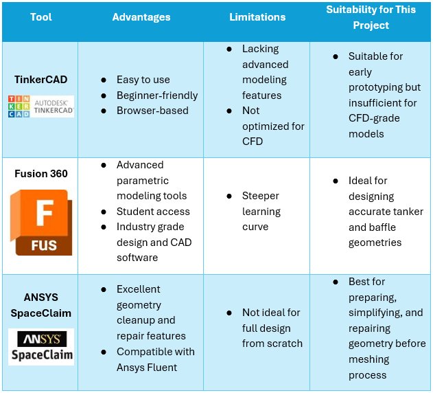 Table 1. Comparison of 3D Modeling Tools
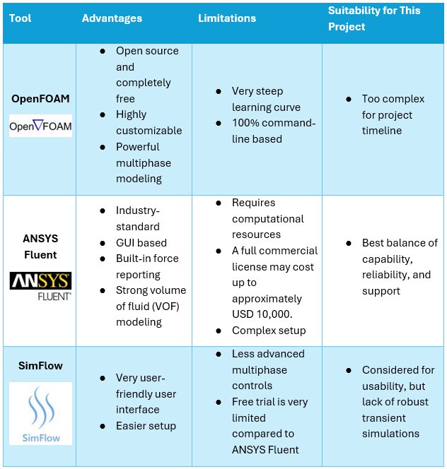 Table 2. Comparison of CFD Tools
Conclusion:
After careful evaluation and discussion with professionals, I selected Autodesk Fusion 360 for its precise geometric modeling, as well as ANSYS SpaceClaim for its robust geometry preparation, simplification, and cleanup. Lastly, I selected ANSYS Fluent for its strong transient CFD simulations and force analysis.
This highly integrated workflow ensured accurate geometry, high quality mesh generation, reliable multiphase sloshing simulations, and consistent force extraction for comparing results from the Standard and Smart Baffle designs. This organized tool selection process allowed for strengthened technical reliability of the project and demonstrated a systematic engineering approach rather than ad-hoc software usage.
Variables
Variables
Independent Variable (Manipulated):
- Internal baffle geometry (Standard Baffle vs. Smart Baffle)
Dependent Variables (Responding):
- Peak lateral sloshing force
- Lateral force oscillation amplitude
- Time required for force stabilization
- Pressure distribution on tank walls
Controlled Variables (Constant):
- Tank geometry and dimensions
- Fluid type (water)
- Fluid density and viscosity
- Initial fill level
- Gravity setting
- Mesh strategy and refinement approach
- Solver configuration (VOF model, turbulence model, time-step size)
- Simulation duration
By controlling all simulation parameters except internal baffle geometry, differences in force behavior can be attributed directly to geometric variation.
Procedure
CFD Methodology
Pre-CFD Geometry Preparation
Before running any CFD simulations, careful geometry preparation was required to ensure numerical stability and simulation accuracy. Although the original 3D models of the Smart and Standard Baffle were created using Autodesk Fusion for physical prototyping, CFD simulations require a simplified and de-featured watertight fluid domain.
Firstly, the 3D models (as. step format) were imported into ANSYS SpaceClaim for geometry cleanup. Unnecessary small features such as lids, sharp edges, and manufacturing details that were irrelevant to fluid flow we removed to reduce the complexity of the mesh. Then, the internal fluid volume was then extracted to define the computational domain. This step ensured that only the fluid region inside the tank would be solved during the simulation.
Next, the geometry was inspected for any gaps, overlaps, or non-manifold edges which could otherwise kill a simulation. Any detected imperfections were repaired to create a fully enclosed fluid body. This was critical to prevent mesh failure or solver instability later in the process.
Both the Standard Baffle and Smart Baffle geometries were prepared with the same procedure, starting with identical tank dimensions to ensure a controlled comparison. The only geometric difference between models was the internal baffle design and structure. Maintaining this consistency allowed for simulation results to isolate the effect of baffle geometry on sloshing forces.
Such careful pre-processing at this stage allowed for the reduction of computational errors, improved mesh quality, and ensured that subsequent CFD simulations would produce reliable and comparable results.
| Standard Baffle | Smart Baffle |
|---|---|
 |
 |
Figure 1: Volume Extract of Standard Baffle and Smart Baffle
Mesh Generation and Quality Control
After geometry preparation was completed, high-quality mesh generation was performed to accurately discretize the fluid domain for numerical analysis. Since CFD solutions depend heavily on mesh resolution and element quality, careful control of mesh parameters was required to ensure accuracy and solver stability during simulations.
A volumetric mesh was generated using ANSYS Meshing. Local mesh refinements were applied to regions with high gradients, including:
- Baffle blade edges
- Tank walls
- Free-surface regions
Refinements in these specific high traffic areas improve the numerical resolution of velocity and pressure gradients, which directly affects force calculation accuracy.
Mesh quality metrics were monitored to maintain numerical reliability:
- Skewness was maintained within acceptable limits to prevent numerical instability.
- Orthogonal quality was controlled to ensure accurate flux computation.
- Total element count was optimized to allow stable transient simulation within available computational resources.
Due to software limitations during early development using the ANSYS Student Version, full mesh-independence testing was not performed. However, identical meshing strategies were applied to both designs, Standard and Smart Baffle to reduce and eliminate any mesh-induced bias. This ensured that differences in results were attributable directly to the geometry variation.
Controlled mesh refinement and quality verification were essential for producing stable simulations and reliable force comparisons.
| Standard Baffle | Smart Baffle |
|---|---|
 |
 |
Figure 2: Generated Mesh for Standard Baffle and Smart Baffle Geometry
Solver Configuration in ANSYS Fluent
After successfully generating accurate meshes for both baffle designs, the simulation was then configured in ANSYS Fluent to accurately represent transient sloshing inside a partially filled tanker. Since sloshing involves not only the simulation of fluid but also requires a moving free surface between the liquid and air, thus a multiphase modeling approach is required.
Physical Models
A Transient Pressure-based Solver was selected because sloshing is time-dependent. Furthermore, gravity was enabled to allow for realistic fluid behavior under acceleration and braking in the simulation.
To model the interface between water and air, a Volume of Fluid (VOF) multiphase model was required. This allowed the model to track the free surface and allows for accurate simulations of wave formation and fluid movement.
A Turbulence Model (e.g., k-ε or k-ω SST or laminar) was applied to the simulation to capture flow separation and turbulence generated around the baffles.
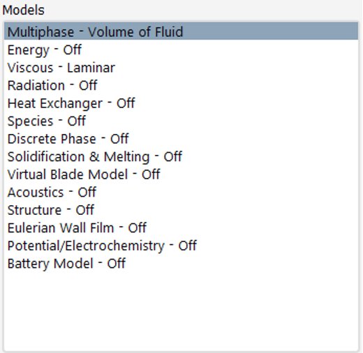 Figure 3: Multiphase (VOF) Model Setup
 Figure 4: Gravity and Operating Conditions Settings
Boundary Conditions
Boundary conditions of the geometry were defined consistently for both baffle designs to ensure fair and scientific rigor in the comparison between baffle designs:
- Tank walls defined as no-slip boundaries
- Initial liquid fill level set identically in both models
- Identical fluid properties (density and viscosity)
The only manipulated variable in the simulations was the internal baffle geometry.
 Figure 5: Boundary Condition Setup
Transient Settings and Convergence
Time step size, as well as the number of timesteps, was carefully selected to capture free-surface and sloshing forces without numerical instability. Residual plots were monitored carefully during calculations to ensure convergence at each time step.
Force monitors were created to record:
- Lateral forces
- Vertical forces
- Pressure forces on tank walls
 Figure 6: Force Monitor Setup
By maintaining identical solver settings across both baffle designs, the simulation results isolate the influence of baffle geometry and sloshing-induced forces. This ensured a controlled and scientifically rigorous comparison.
Simulation Execution and Force Extraction
After configuring the CFD solver, transient VOF simulations were executed for both the Standard and Smart baffle models under identical initial boundary conditions. Each simulation was run for the same physical time duration to capture the full sloshing cycle and force stabilization behavior.
During calculations, residuals were continuously monitored to ensure numerical convergence at each time step. Simulation stability was carefully observed to prevent any divergence caused by free-surface instability or excessive time-step size. Any instability detected early in calculations was resolved by refining time-step size and improving mesh quality near high-gradient regions if needed.
Observations
Observations
Force Monitoring & Data Extraction
To numerically quantify sloshing behavior and wave force inside the tank, force monitors were defined on the internal tank walls. The following quantities were extracted over time:
- Lateral force (Side-to-side force contributing to rollover risk)
- Vertical force variation
- Total pressure force fluctuations.
Force-time histories were exported for both designs and compared based on:
- Peak force magnitude
- Force fluctuation amplitude
- Time required for force stabilization
Force-Time Comparison
Pressure contour analysis revealed distinct differences in internal flow behavior.
The Standard Baffle configuration showed:
- Concentrated high-pressure regions near tank walls
- Steeper free-surface gradients
- Pronounced wave impact zones
The Smart Baffle configuration showed:
- More evenly distributed pressure contours
- Reduced free-surface slope
- More fragmented internal circulation patterns
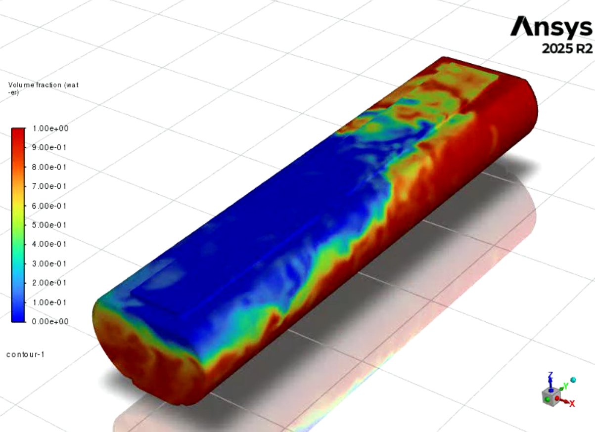
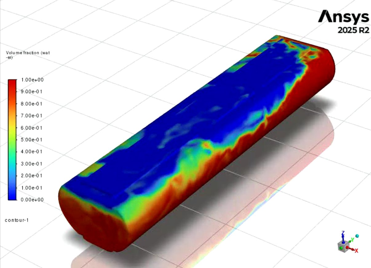
| Time | Standard Baffle | Smart Baffle |
|---|---|---|
| 0 sec | 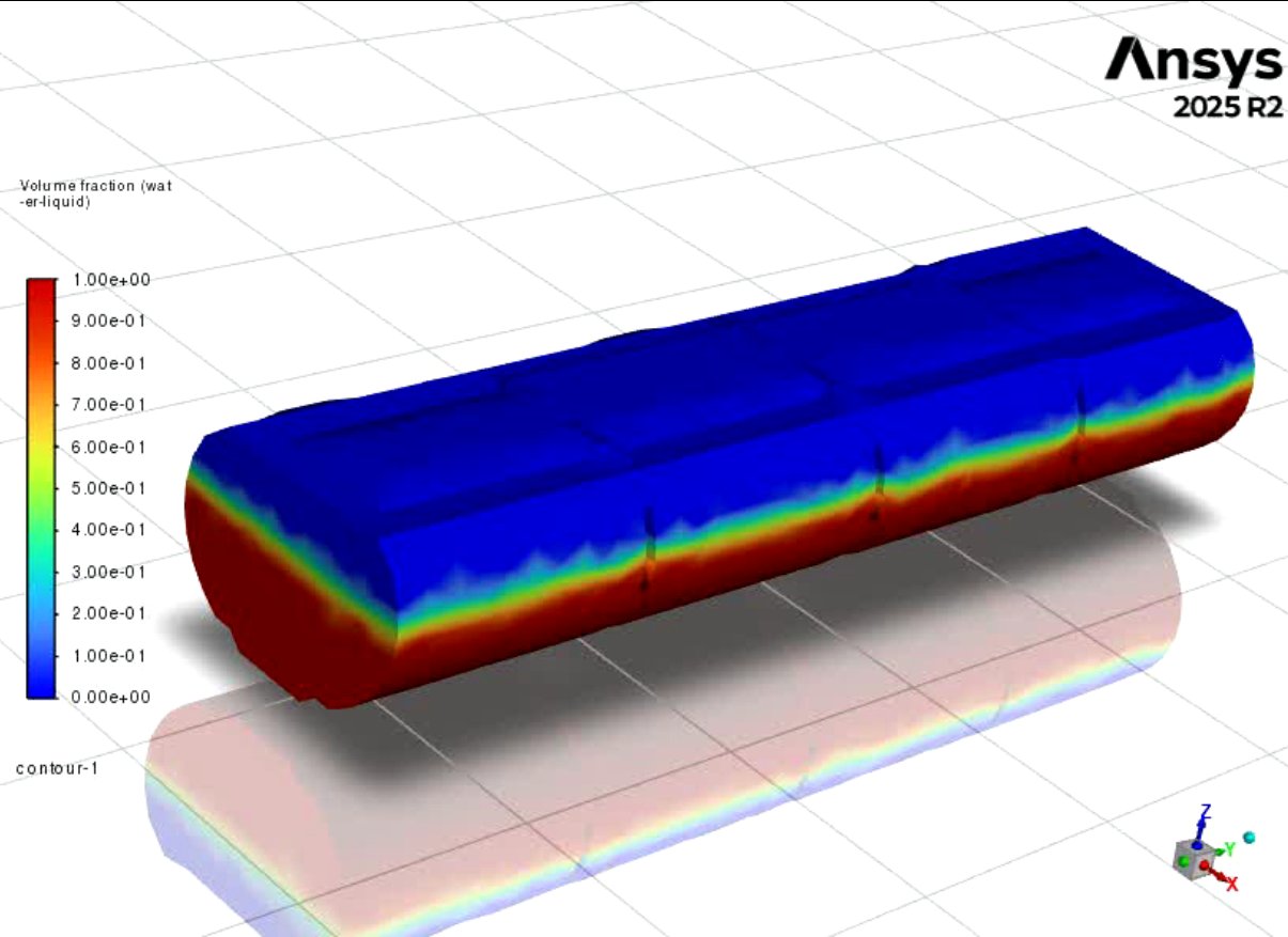 |
 |
| 15 sec | 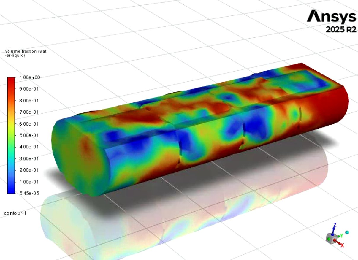 |
 |
| 30 sec | 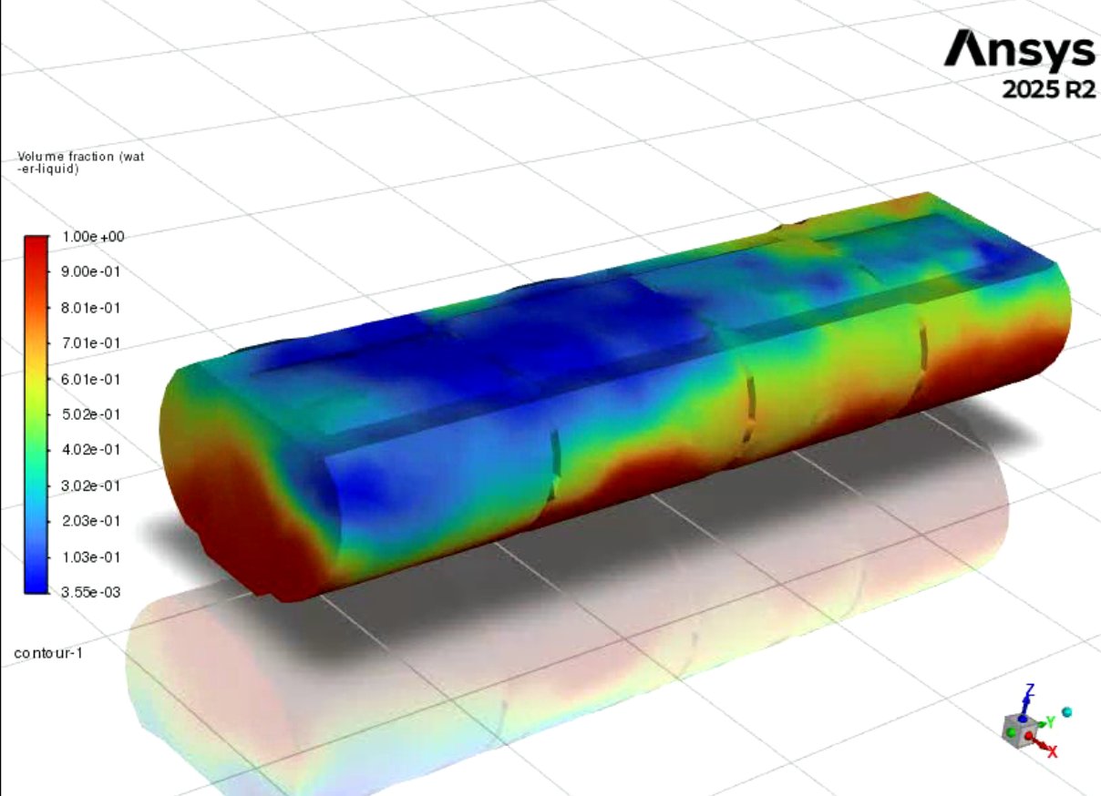 |
 |
| 45 sec | 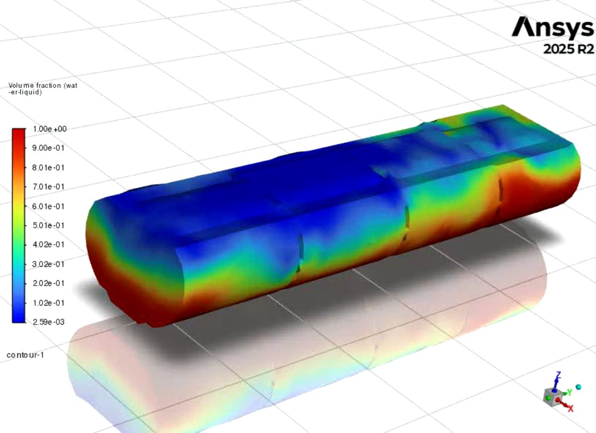 |
 |
| 60 sec | 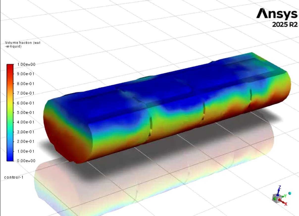 |
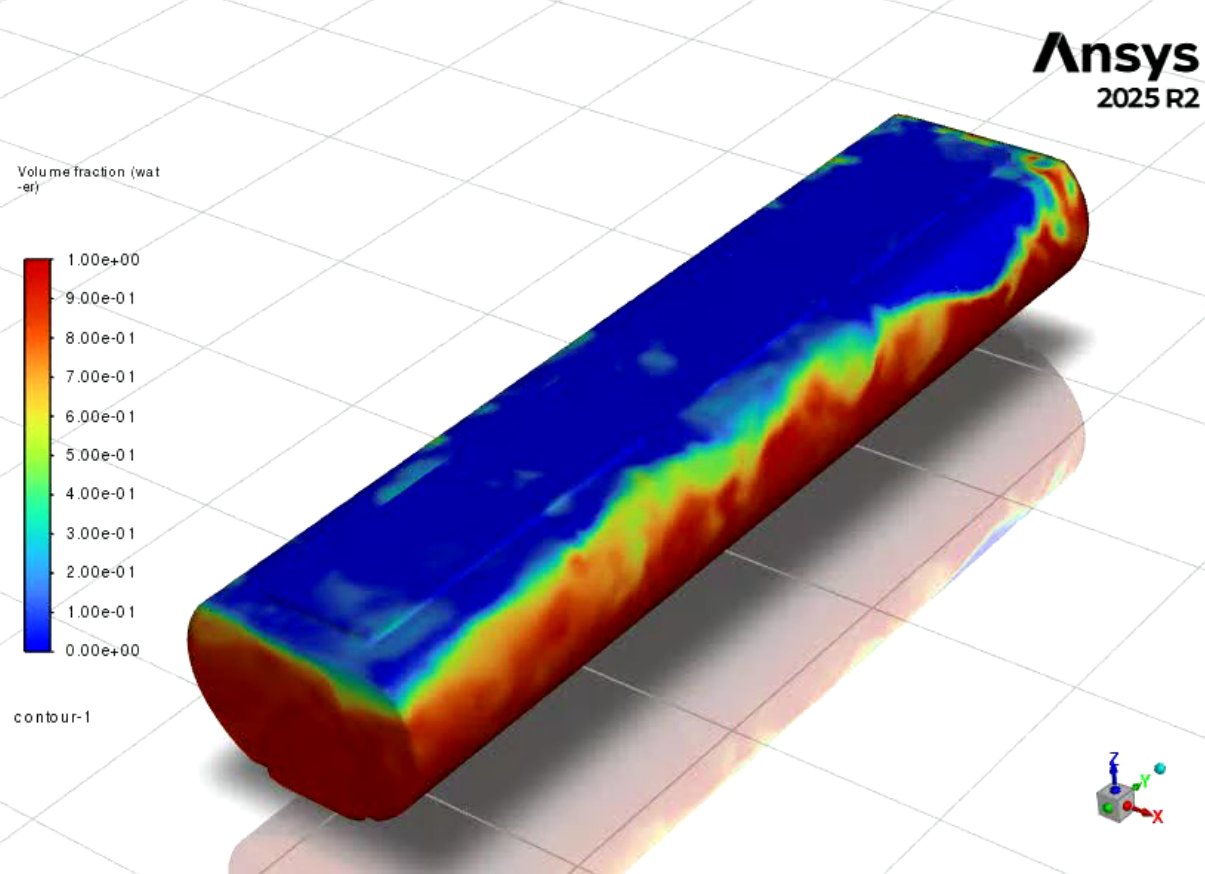 |
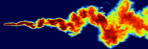
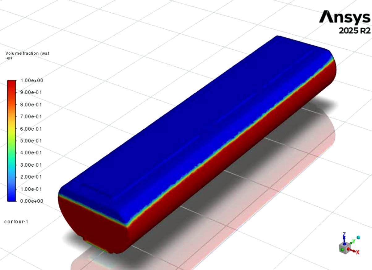
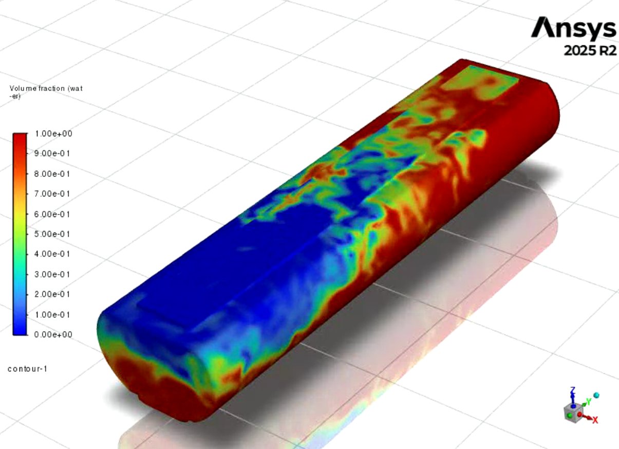
Figure 7: Free-surface Animation Snapshots
Time-Resolved Free-Surface Evolution (VOF Analysis, 0–60 s)
Time-matched Volume of Fluid (VOF) snapshots were analyzed at 5-second intervals from 0 s to 60 s for both configurations.
Early Stage (0–15 s):
- Both models began with identical flat free surfaces.
- The Standard Baffle developed a coherent longitudinal wave.
- The Smart Baffle showed more distributed deformation with less continuous wave crest formation.
Mid Stage (20–40 s):
- The Standard Baffle maintained a dominant tank-spanning wave with visible end-wall reflections.
- The Smart Baffle exhibited reduced wave coherence and smoother interface gradients.
Late Stage (45–60 s):
- The Standard Baffle continued to show residual large-scale oscillatory motion.
- The Smart Baffle displayed reduced tank-spanning slope and smaller localized fluctuations.
Across all time intervals, the Standard configuration demonstrated more persistent coherent wave structures compared to the Smart configuration.
Numerical Convergence Comparison
Residual plots were used to check whether both simulations were stable and reliable.
In both the Smart and Standard baffle cases, the residual values decreased and stayed within acceptable ranges. There was no sign of solver divergence or numerical failure. This means both simulations were stable and suitable for comparing results.
However, some differences were observed:
- The Standard Baffle showed larger and more frequent residual oscillations, especially in the volume fraction (water–air interface).
- The Smart Baffle showed smoother residual behavior and more steady stabilization over time.
In sloshing simulations, some oscillation in residuals is normal because the water surface is constantly moving. The larger oscillations seen in the Standard case are consistent with its stronger wave motion. The smoother pattern in the Smart case matches its more controlled internal flow behavior.
Overall, both simulations converged properly, and the differences in force results are due to baffle geometry, not numerical errors.
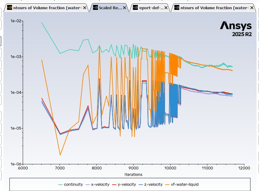 Figure 8a: Residual Convergence Plot - Standard Baffle
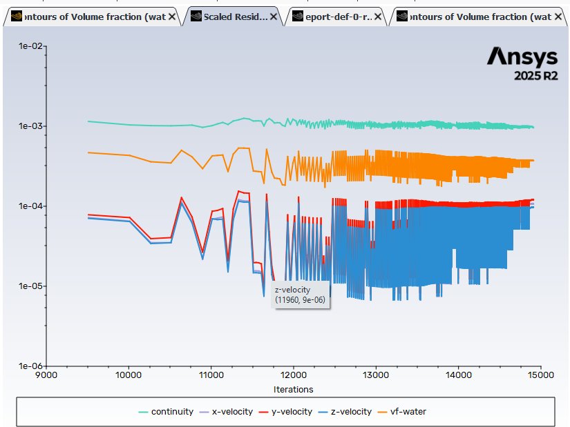 Figure 8b: Residual Convergence Plot - Smart Baffle
Flow Behavior Analysis
Visualization tools in Fluent were used to analyze velocity vectors, pressure contours, and free-surface deformation. The Standard Baffle model showed:
- Larger free-surface waves
- More concentrated high-pressure regions
- Greater force oscillation over time
In contrast, the Smart Baffle model demonstrated:
- Redirected swirling flow patterns
- More distributed pressure fields
- Reduced peak force values and smoother force decay
These simulation results provided computational validation of last year’s physical findings, demonstrating that the Smart Baffle geometry reduces sloshing-induced forces rather than only improving external braking performance.
By extracting quantitative force data and combining it with flow visualization, this stage transformed the project from observational testing into force-based engineering validation.
Analysis
Engineering Analysis
Wave Coherence and Momentum Redistribution
The observed formation of coherent longitudinal waves in the Standard configuration indicates bulk fluid translation across the tank length. Such motion allows large volumes of liquid to shift collectively, increasing transient lateral loading. In contrast, the Smart Baffle disrupts large-scale wave coherence and redistributes internal fluid momentum into smaller circulation structures. This limits bulk mass translation and reduces concentrated lateral force development.
Mechanism of Force Reduction
The steeper free-surface gradients observed in the Standard configuration correspond to larger hydrostatic pressure variation along tank walls, contributing to higher peak lateral forces. The smoother interface behavior in the Smart configuration is consistent with reduced pressure concentration and lower transient force magnitude. The distributed circulation patterns observed in the Smart case reduce the formation of dominant impact regions along the tank boundaries.
Oscillation Persistence and Dynamic Stability
The longer persistence of oscillatory motion in the Standard configuration indicates slower attenuation of sloshing motion. The earlier stabilization observed in the Smart configuration suggests improved internal flow control under identical excitation conditions. Reduced oscillation amplitude and shorter duration of force fluctuation are consistent with enhanced dynamic stability of the liquid mass
Correlation with Previous Experimental Findings
The computational results align with previous physical testing, where the Smart Baffle reduced braking distance and visible sloshing behavior. The CFD analysis now provides quantitative internal force measurements that support and explain those earlier experimental observations.
Conclusion
Results and Conclusions
This project advanced the Smart Baffle design from physical prototyping to computational validation. By applying Computational Fluid Dynamics (CFD) using ANSYS Fluent, I quantitatively analyzed how internal baffle geometry influences sloshing forces within a partially filled tanker.
The simulation results demonstrate that the Smart Baffle reduces peak lateral forces, lowers force oscillation amplitude, and promotes faster stabilization of internal fluid motion compared to a Standard Baffle. Pressure contours and time-resolved VOF visualizations further show that the Smart Baffle disrupts large coherent sloshing waves and redistributes internal fluid momentum into more controlled circulation patterns.
These findings computationally support last year’s experimental observations and strengthen the engineering foundation of the Smart Baffle concept. By integrating 3D modeling, structured meshing, transient multiphase simulation, and quantitative force extraction, this investigation demonstrates how simulation-based analysis can enhance design evaluation, improve predictive reliability, and support safer tanker configurations.
Beyond the technical results, this project reflects significant growth in independent learning, advanced problem-solving, and application of professional engineering tools. It illustrates how computational modeling can transform an innovative concept into a quantitatively supported engineering solution with meaningful implications for safer liquid transport.
Application
Application
The results of this investigation have direct implications for road safety and hazardous material transport. Fuel tankers and liquid cargo vehicles are especially vulnerable to rollover accidents when partially filled, due to internal sloshing forces generated during braking, acceleration, and turning. These forces shift the vehicle’s center of mass and create destabilizing lateral loads that can lead to loss of control.
By reducing peak lateral sloshing forces and lowering force oscillation amplitude, the Smart Baffle design may decrease the magnitude of destabilizing loads acting on tanker walls during sudden maneuvers. Reduced internal force fluctuations can contribute to improved dynamic stability, more controlled vehicle response after braking or turning, and potentially lower rollover risk under comparable operating conditions.
Improved tanker stability can help reduce:
- Traffic accidents involving heavy liquid cargo vehicles
- Environmental damage from fuel spills
- Road closures and economic disruption
- Injury risk to drivers and surrounding motorists
Beyond fuel transport, similar baffle optimization principles may be applied to chemical tankers, agricultural liquid transport, and other partially filled cargo systems where sloshing contributes to instability.
By enhancing internal flow control, optimized baffle geometry has the potential to improve transportation safety and reduce the societal and environmental impact of tanker rollover accidents.
Sources Of Error
Technical Challenges and Problem-Solving
Transitioning from physical prototyping to CFD simulation presented significant technical challenges. Unlike experimental testing, CFD requires careful numerical setup, computational stability, and validation of assumptions. Throughout this project, numerous technical obstacles were encountered and systematically resolved.
Geometry and Meshing Challenges
One of the first challenges I encountered was preparing simulation-ready geometry. My original CAD 3D models were designed solely for the purpose of 3D printing, not fluid simulation. Small gaps, sharp edges, and overlapping surfaces initially cause a myriad of mesh failures and solver errors.
To resolve such issues, I:
- Simplified non-essential features such as embossed text and fillets
- Repaired non-manifold edges in SpaceClaim
- Exclusively extracted the volume of the CAD 3D models
- Ensured watertight fluid domains
- Applied local mesh refinement near high-gradient regions
Improving geometry quality significantly reduced meshing errors and enhanced solver stability.
Solver Instability and Convergence Issues
During early simulation runs, divergence occurred due to free-surface instability and aggressive time-step sizes. Sloshing simulations are highly sensitive to time resolution and turbulence modeling. To address these, I:
- Reduced time-step size to improve numerical stability
- Adjusted under-relaxation factors
- Monitored residual convergence at each time step
- Refined mesh near the free-surface region
Through iterative adjustments, stable transient solutions were achieved.
Learning Advanced CFD Concepts
This project required understanding concepts way beyond my grade level, including:
- Multiphase Volume of Fluid (VOF) modeling
- Turbulence models (k-ε / k-ω)
- Force extraction and pressure integration
- Transient flow behavior
Since I had zero prior CFD experience, I completed self-paced tutorials, reviewed documentation, completed online CFD courses, and sought guidance from university professors. I also used AI responsible to clarify technical settings and help interpret solver outputs.
Validation and Fair Comparison
Ensuring a fair comparison between Standard and Smart Baffles required strict control of:
- Mesh density
- Fluid properties
- Initial conditions
- Solver settings
The only manipulated variable was the internal baffle geometry, and this systematic approach ensured that observed differences were only due to design geometry, rather than numerical bias.
Summary
Overcoming these challenges strengthened both the technical reliability of the results and my understanding of computational fluid dynamics. The iterative problem-solving process transformed this project from software operation into a structured and rigorous engineering investigation.
Limitations and Future Work
Limitations
Although at the end of the day this CFD investigation was able to provide quantitative validation of the Smart Baffle design, several limitations should be acknowledged.
First, the simulations were conducted using scaled geometries and simplified fluid properties. While water was used as the working fluid and gravity-driven sloshing was modeled, real fuel transport may involve different densities, viscosities, and dynamic driving conditions. Therefore, the simulation results can only represent controlled comparative conditions, rather than full-scale real-world operations.
Secondly, early development was conducted using ANSYS Student Version, which contained significant restrictions on mesh element count and advanced solver features. These limitations required additional mesh optimization efforts and reduced simulation resolution in early trials, increasing computational time and iteration cycles. Due to these restrictions, some high-resolution transient studies were not initially feasible.
However, after continued effort and communication, I obtained an academic license from ANSYS, which allowed me to access advanced features and higher mesh limits. This license significantly improved simulation stability, mesh refinement capability, and result accuracy.
I also explored various other alternative CFD platforms. I contacted SimFlow for potential academic access but did not receive a response. The available free trial imposed strict meshing restrictions that prevented high-quality transient sloshing simulations. Therefore, it was not suitable for this investigation.
Finally, although mesh sensitivity was considered, a full formal mesh-independence study could be expanded further in future work.
Future Work
Future research could extend this project in several directions:
- Conducting a full mesh-independence study with quantitative convergence analysis
- Simulating different fill levels to study partially loaded tank behavior
- Testing different fluids with varying densities and viscosities to represent different fuels
- Incorporating vehicle acceleration profiles instead of gravity-only assumptions
- Performing Fluid-Structure Interaction (FSI) analysis to model tank wall deformation
- Validating CFD results with additional high-speed physical experiments and testing
- Optimizing Smart Baffle geometry to be more effective at dampening sloshing forces
With access to expanded computational resources and advanced simulation tools, future work could move toward industry-scale modeling and broader application in liquid transport safety.
Citations
References
1. ANSYS\, Inc. (2024). ANSYS Fluent user’s guide (Release 2025 R2). ANSYS, Inc.
2. ANSYS\, Inc. (2024). ANSYS meshing user’s guide (Release 2025 R2). ANSYS, Inc.
3. ANSYS\, Inc. (2024). ANSYS SpaceClaim user’s guide. ANSYS, Inc.
4. Ferziger\, J. H.\, & Perić\, M. (2002). Computational methods for fluid dynamics (3rd ed.). Springer. https://doi.org/10.1007/978-3-642-56026-2
5. Hirt\, C. W.\, & Nichols\, B. D. (1981). Volume of fluid (VOF) method for the dynamics of free boundaries. Journal of Computational Physics, 39(1), 201–225. https://doi.org/10.1016/0021-9991(81)90145-5
6. Ibrahim\, R. A. (2005). Liquid sloshing dynamics: Theory and applications. Cambridge University Press. https://doi.org/10.1017/CBO9780511536656
7. Munson\, B. R.\, Okiishi\, T. H.\, Huebsch\, W. W.\, & Rothmayer\, A. P. (2013). Fundamentals of fluid mechanics (7th ed.). Wiley.
8. Versteeg\, H. K.\, & Malalasekera\, W. (2007). An introduction to computational fluid dynamics: The finite volume method (2nd ed.). Pearson Education.
9. White\, F. M. (2016). Fluid mechanics (8th ed.). McGraw-Hill Education.
10. ANSYS Learning Forum. (2024). VOF modeling guidelines and best practices. https://forum.ansys.com
Acknowledgement
Acknowledgements
I would like to express my heartfelt gratitude to everyone who was involved and supported me throughout this project.
I am especially grateful to Dr. Schuyler Hinman from the University of Calgary, at the Department of Mechanical and Manufacturing Engineering, who kindly took the time to meet with me and provide invaluable guidance on my CFD methodology and research direction. His insights helped strengthen my understanding of CFD as well as maintaining scientific rigor.
Additionally, I would also like to thank Autodesk and ANSYS for allowing me academic access to their software, which enabled me to perform simulations with higher accuracy. Furthermore, I am greatly thankful for all the online educational resources, open-source communities, as well as technical documentation that supported my independent learning.
Finally, I am deeply thankful to my teachers, science fair coordinators, and most of all, my parents for their continuous encouragement, support, and guidance.