
How Do Traffic Lights Work?
Grade 5
Presentation
Hypothesis
If we put all the wires, resistors, and LED lights on the right spots on the breadboard, connect all the wires on the correct pin on the Arduino board, and accurately code the times for each traffic light, then the process should work properly and resemble real traffic lights, because our research shows that exact and perfectly timed coding will result in properly functioning traffic lights.
Research
RESEARCH
Question: How does a traffic light system work?
Source:https://nacto.org/publication/urban-street-design-guide/intersection-design-elements/traffic-signals/signal-cycle-lengths/#:~:text=The%20amount%20of%20green%20time,decreases%20congestion%20on%20surrounding%20streets
Source:https://amperite.com/blog/how-does-a-traffic-light-system-work/#:~:text=Under%20the%20road%2C%20an%20inductive,or%20cameras%20to%20detect%20vehicles
- Red means stop, yellow means get ready to stop, and green means go.
- Traffic lights either use timers or sensors. Each one is used for different types of intersections depending on what is better for that specific road.
- Most common system is the timer-based system, more commonly used in busier, high traffic areas.
- At intersections where traffic is variable, fixed-time traffic lights are not efficient. Drivers often have to wait longer and that can cause frustration and a possible build up of traffic.
- In rural areas with sparse or unpredictable traffic flows, sensors are a better choice.
- In urban areas, short cycle lengths of 60–90 seconds are ideal to keep traffic of cars and people flowing smoothly.
- Traffic lights keep drivers and pedestrians safe.
- Each set of traffic signals has a traffic signal controller box. This box contains the electrical wiring and a microprocessor control unit which communicates with the central computer located somewhere else in the city. The computer, also knows as the brains, contains the data needed to make traffic lights work properly and it is specific to that intersection. This box also contains a backup battery in case the power goes out.
- There are many ways that these controllers work to control traffic. Through detection, multiple types of sensors, cameras, and even a smart traffic light system.
Source:https://www.greenlighttrafficengineering.com/what-is-traffic-engineering/
Research question: What do traffic engineers do?
- Traffic engineers deal with the safe and efficient movement of people and goods on roadways.
- They work hard to make sure that roads are designed and operate in a way that reduces congestion and accidents.
- Traffic engineers are responsible for the planning, designing, and operation of traffic lights.
- They often use computer simulations to test various traffic scenarios before implementing changes on real-world roads.
Questions for a Traffic Engineer:
Q1.
- How do traffic engineers ensure safe placement as well as safety of traffic lights in different areas and weather scenarios?
-
To ensure safety of the traffic lights and road users, traffic engineers perform a study of vehicles passing the intersection based on the posted speed, and examine the area based on weather conditions and land. Safety is ensured in the design & construction phases which involves careful placement of traffic signals dependent on area, as well as careful selection of materials based on specifications, weather resistance. Safety codes & review of tests are always performed before implementing and installation.
-
Q2. We learnt that for sensors detecting a car, there is always a box in the area that transmits the signal, is there a separate box for timers of all the signals as well ? Why or why not ?
-
- No, there isn’t a separate box for each signal timer controller, just one main central box for the whole intersection, because:
- Ease of access to maintain & during troubleshooting, a single key opens the small cabinet box for checking everything simultaneously in one place.
- These are small size components not requiring much space, they have to be connected to each other by means of wiring just like a CPU of desktop PC is connected to monitor, keyboard, mouse, camera, etc.
- The box also houses a backup battery for traffic signal operation in case of electrical power failure.
- No, there isn’t a separate box for each signal timer controller, just one main central box for the whole intersection, because:
Variables
Controlled Variables:
- Breadboard
- Jumper Wires
- Arduino Board
- 220 Ohm Resistors
- LED lights
- Setup Instructions
- 9 Volt Battery
- Laptop
Manipulated Variables: The coding entered on the laptop instructing the traffic lights when to turn and off and for how long.
Responding Variables: The order and timing of the 6 LED lights turning on and off, to make it work like a traffic signal.
Procedure
Step by Step Procedure:
1. Gather all our information and materials needed for the experiment.
2. Follow instructions on how to build the traffic light system.
3. Place the LED lights, resistors, and wires on the right place on the breadboard.
4. Connect the wires to the Arduino board to create a circuit.
5.Plug in the USB cable from the laptop to the Arduino board.
6. Name the LEDs accurately based on the pins they correspond to for correct results.
7. Begin coding by entering the information for when lights should be on or off and for the right number of seconds
8. Press verify, then upload button for the coding to be transferred to Arduino board.
9. Check if the traffic light LEDs light up in the correct order and the right time.
10. Repeat the process until we get the results we want.
Observations
For our traffic light system, we started off by setting up the breadboard and Arduino board. Then we started coding. Each time we verify and upload the code onto the Arduino Board, we waited to see how the lights are working. We had some trials and errors along the way until we got the results we wanted.
- The materials placed on the breadboard need to be placed correctly so it can conduct electricity in a loop.
- Breadboard is representing tap points. If the wire is not connected properly, lights do not work because the connection is not made.
- This is a closed circuit.
- The LED light placed on the breadboard has 2 pins (long end and short end). One pin is connected to the resistor, other pin is connected to the jumper wire.
- Resistor is used to control the flow of electricity to LED lights as we have learnt in our science unit.
- Jumper wires are used to conduct the electricity. They are placed in a loop. One wire is on the negative bus of the breadboard, and other wire is connected to the LED light.
- The green wire, also the ground wire, provides a path for electricity to run through the circuit. Without this wire connected properly, nothing will work.
- Loop is from the microprocessor (Arduino board where the coding is uploaded) to the breadboard and back.
- All this is connected to a 9V battery which powers the Arduino Board
- Laptop can also be used to power the Arduino Board.
- The USB cable is a direct connection between the Arduino Board and the laptop, allowing to upload the code right away.
- The coding on the computer looks very confusing but reading instructions is helpful to understand.
- Any small mistake iN coding results in lights not working properly
- It is very important to make sure that the LED connecting to the Arduino Board pin is propoerly coded based on the pin number, otherwise we code the wrong light and it is not correct.
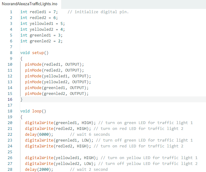
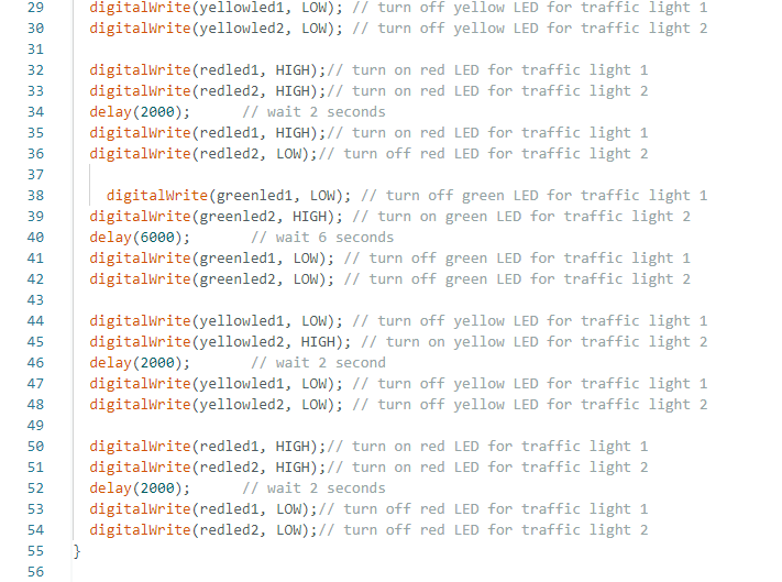
- When initializing the digital pin, it is important to label it correctly. We labeled them so we knew which light we were coding and timing and had to make sure it corresponds with the correct pin on the Arduino Board, which should be connected with wire to the correct LED light.
- HIGH means the LED light will be on.
- LOW means the LED light will be off.
- The microprocessor uses 1000th of a second for its coding. So, if we want the light to be on or off for 2 seconds, the code we enter after ‘delay’ would be ‘2000’. For 6 seconds, we would enter ‘6000’. This helped us make sure the right timer was on, if we wrote just 2 or 6, it would not work.
- To make sure we do not lose track, we wrote down what each line meant.
|
Trial 1 |
The traffic lights started off with a trailing light effect with all the lights turning on one after the other. We had to fix that because that is not what we want. |
|
Trial 2 |
The yellow light kept blinking while the other lights turned on at the right times and order. |
|
Trial 3 |
We made a mistake by deleting an important section of the coding, so none of it worked, had to rewrite the code again. |
|
Trial 4 |
The yellow LED stopped blinking and the 3 sets of lights turned on like an actual traffic light |
|
We decided to add another traffic light to our system. So we had to set up another set of LEDs, resistors, and wires, as well as add more details to the coding to make sure that both traffic lights were set up properly. |
|
|
Trial 5 |
When code is uploaded, we notice that all the LEDs were on at the same time. |
|
Trial 6 |
We managed to get only 2 lights on at the same time. Traffic light 1's green LED was on, while traffic light 2's red LED was on as well. |
|
Trial 7 |
We tried changed the code so that the correct lights were on and off for the right amount of time. Most of it worked, but the yellow failed to turn off and the red was on at the same time as the yellow. |
|
Trial 8 |
We fixed all the mistakes in our coding, and our traffic light system is working perfectly. |
Analysis
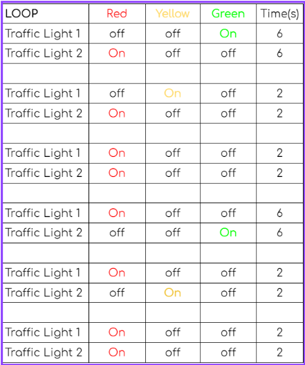
RESULTS WE WANTED TO GET:
Analysis of the results:
The loop we have coded was as close as possible to traffic lights we could get. We did not take into account the left turn signal, or pedestrian crossing in our project.
We created a traffic light system which is perpendicular to each other. So when one traffic light is green, the other one has to be red, otherwise the cars will crash into each other.
Traffic Light 1 has the green light on for longer allowing traffic to flow through it. Then the yellow light is turned on for a shorter amount of time to let the traffic to know that they need to get ready to stop. The red light is then turned on for the traffic to come to a complete stop. While Traffic Light 1 allowed traffic to go through, Traffic Light 2 had only the red light on during that whole time so there are no car crashes.
An important part of our results sheet is to notice that for a small amount of time, both traffic signals have just the red light on at the same time. We believe this is to leave a few seconds in between for cars to make it through if they got on the road when it was yellow and turned red halfway through. This is a good idea to avoid car crashes. If the green from traffic light 2 turns on right away, there is high chance of frequent car crashes.
The signal cycle repeats with Traffic Light 2 turning green, while traffic light one stays red.
This loop we created made us realize that traffic light signals are very important for traffic to flow smoothly. The traffic engineers have a very important job that requires a lot more that what we did. Our system was simple, and our coding times were less and not reflecting the times of an actual signal as they also vary based on the location and traffic flow of the road. We also did not have pedestiran cross walks or left turn signals to account for. A trafiic engineer's job is to monitor, research, and figure out the best system for roads and this is a very important job.
Conclusion
In conclusion, our hypothesis was proven correct. By putting the wires, LEDs, and resistors in the right spot on the breadboard and Arduino board, and coding the information correctly, we figured out how to do make the traffic light work and we got the end results we wanted. The traffic lights were working in the correct order with the right times.
Application
We use traffic lights in our everyday lives. They help with the flow of traffic, and also help us avoid car crashes. They make the traffic run smoothly, and keep everyone safe. The colors on the traffic light indicate how we should react. Red for stop, yellow for get ready to stop, and green for go.
We have realized the importance of traffic lights, based on all the information we have collected. If anyone should have the credit, it would be our traffic engineers. They are responsible for the operation of traffic lights, and making sure it works. Knowing how traffic lights work is very important, as millions of people around the world depend on them.
Extension:
If we were to be doing the experiment differently, we would add the use of pressure sensors or motion sensors. The sensors are used in more rural areas, and timers are used for more urban areas. We did timers for this project, so for future projects, we might do sensors. It would be more work, but we want a challenge, and we will be up for it. We could also make it a 4-traffic light signal with left turn signals. This would require a lot more coding and precision. Along with that, adding a pedestrian crosswalk, and putting the correct signage for our display model would also something we would like to consider doing.
Sources Of Error
Possible sources that interfere with our results:
- A loose connection on the breadboard, this would break the circuit connection, and electricity cannot flow, so the LED with a loose connection would not turn on.
- Human errors:
- Placing the jumper wire in the wrong spot, not allowing for a connection be made.
- Forgetting to add the ground wire to the Arduino board, the whole circuit will not work.
- Entering coding that does not match the traffic light color.
- Confusing the LEDs and wires and entering the incorrect name when coding.
- A fused LED bulb
- Uncharged battery
Citations
https://www.smraza.com/products/
https://amperite.com/blog/how-does-a-traffic-light-work/
https://www.greenlighttrafficengineering.com/what-is-traffic-engineering/
https://www.cityworks.com/blog/7-fascinating-facts-about-traffic-lights/
Acknowledgement
Parents: Noor Waseem, Ali Sheikh, Reem Siddique, Mirza Danish Baig
Teacher: Mrs. Bosman, Ms. Deb
Traffic Engineer: Mr. Affan