Exploring The Design And Physics of Solar Sails, Including Their Applications in a Telescope at the Solar Gravitational Lens (SGL)
Grade 10
Presentation
Problem
The James-Webb Space Telescope (JWST) is considered by many to be the largest, most powerful telescope to be launched into space, providing insights into every phase in the history of our universe, including the start of the Big Bang, formation of bodies capable of supporting life, and evolution of our own solar system. However, despite its capabilities, current telescopes face fundamental limitations in magnification and resolution, restricting our ability to directly image exoplanets. As objects become more distant, the images we capture become increasingly blurred. In order to appetize our imaging needs and overcome these imaging challenges, we need telescopes significantly larger than ever before. That reality has started to become increasingly implausible due to technological, physical, and logistical restraints. This major limitation has hindered our ability to deepen and confirm our understanding of celestial bodies outside our solar system, preventing us from taking the next major leap in space sciences.
A potential solution to evolve our technology and extend current capabilities is the use of the sun as a Solar Gravitational Lens (otherwise known as an SGL). By harnessing the Sun's immense gravitational field as a natural lens, we can achieve unprecedented magnification and resolution capabilities, creating an optical system far larger than any human-made telescope. The benefits of this method have the chance to completely transform extrasolar research, with the potential to visibly confirm and map out the geography of an exoplanet. Furthermore, an SGL could enable the detection of liquid water or macroscopic life on an exoplanet. Such a discovery would be revolutionary; inspiring future interstellar missions, reshaping our current understanding of habitable environments, and altering the way we approach the universe.
Despite the undeniable benefits, the intricacies of such a mission of this magnitude present significant challenges. There are concerns about transporting the instruments required to a magnification point capable of using the sun as a lens. This is one of the key obstacles—positioning an observational instrument at the required focal point of an SGL, which is at least 550 AU away, surpassing the orbit of Pluto. Such incredible distances make propulsion a major concern. The propulsion demands for such distances are immense, making traditional propulsion methods, such as chemical rockets and ion thrusters, inefficient and infeasible.
An effective and plausible solution to this issue is the use of solar sails. Unlike conventional propulsion systems, solar sails require minimal fuel, instead relying on solar radiation (sunlight) to generate thrust. This makes them an energy-efficient, low-maintenance sustainable option for deep-space travel. In a potential SGL mission, solar sails could serve as both the primary means of propulsion, and as the main body for capturing and processing light bent by the Sun's gravity.
To demonstrate the feasibility of this approach, this project will focus on two key aspects of an SGL mission:
1. Developing, understanding, and eventually creating a scalable prototype of a solar sail using 3D printing techniques to explore its effectiveness and applications in deep-space exploration.
2. Understanding how solar gravitational lensing works, including its benefits/drawbacks, and further investigating image distortions (Einstein rings) caused by the use of gravitational lensing, which will allow us to explore methods of distortion reversal, including potential computational models.
If solar sails prove to be an effective solution for the challenges of transporting an SGL mission, they could revolutionize deep-space exploration when used with SGLs, enabling imaging capabilities that will allow for direct exoplanet imaging with unprecedented detail, highlighting how SGLs may be the revolutionary technology required to make the next step in astronomical observations. Simultaneously, this success will demonstrate how solar sails are an effective novel method of space transport. The implications of such advancements are vast, with the ability to expand our current knowledge of the universe, exoplanets, and potentially pave the way for future interstellar travel.
Method
Abstract
This science project revolves around introducing a revolutionary method of exoplanet imaging using a Solar Gravitational Lens (SGL), where the Sun's gravity is used to warp rays of light to a single point, greatly increasing the resolution and magnification of imaging devices on this focal point (550 AU+). This method of imaging allows for direct exoplanet observation, with the potential to image surface features. By providing an in-depth understanding of solar sail physics, this project will underline the exceptional high velocity and acceleration solar sails can achieve and therefore, their superiority in deep-space travel as supreme alternatives to traditional methods of propulsion including chemical rockets and ion thrusters. This project also provides an understanding of SGL drawbacks and distortions as well as methods for reversal in order to create clear, detailed images surpassing the capabilities of current telescopes. I propose using my own design of a hybrid solar sail as a transport method for an array of imaging devices, each used to image a single pixel of an exoplanet. If done correctly, this innovative method of imaging will allow for unprecedented detail that revolutionizes the field of telescopy.
1.2.Broad History And Review
Solar sails represent a revolutionary advancement in space propulsion, offering a fuel-free and efficient method for long-term space exploration. However, in the grand scheme of space exploration, solar sails are a relatively recent technology. Other methods of propulsion, including chemical and ion thrusters, have existed and been in use for much longer and are therefore far more widespread. Since solar sails are still an emerging technology, they have only just begun developing but are a promising alternative for missions requiring sustained acceleration over vast distances. To appreciate their potential in Solar Gravitational Lens (SGL) missions, it is essential to explore their historical development and technological evolution.
While solar sails have yet to see widespread application and use in space travel, they have existed as a theoretical technology for years. The concept of solar sailing dates back nearly 400 years to the work of Johannes Kepler, the astronomer who formulated the laws of planetary motion. Kepler first hypothesized the idea when observing comets: he noticed their tails always pointed away from the sun and theorized that a "solar breeze" was responsible for the behaviour. He later suggested that in order to effectively travel through spacecraft, a spacecraft should be equipped with a sail capable of harnessing the solar winds in order to propel itself (Coulter, 2008). However, we now know that solar sails do not rely on solar winds, but rather on the pressure exerted by photons from the Sun's light. Although his idea of harnessing solar winds was later refined, Kepler's insight laid the foundation for the modern understanding of solar sails.
In the 1860s, James Clerk Maxwell's groundbreaking work on electromagnetism provided the scientific basis for solar sailing. His additions proved that light can exert pressure on physical objects. This transformed solar sailing from a speculative idea to a scientifically grounded concept. The first practical demonstration of this principle occurred in 1962, informally tested by NASA on the Mariner 1 spacecraft. After the probe lost significant amounts of propellant due to a calibration and navigation error, NASA engineers used solar pressure to exert thrust on the spacecraft's solar panels and antennae, re-orienting itself to correct its course (NASA & Johnson, n.d.). The success of this maneuver was sufficient to demonstrate that solar sails were a viable method of propulsion.
A more deliberate test of solar sailing occurred in 1964 with NASA's Echo II satellite: a spherical, 41-meter balloon-like inflatable spacecraft placed in near-polar orbit. Its shape minimized solar pressure torque allowing for direct observation of the effects of solar thrust on spacecraft orbit. The data gathered from Echo II advanced NASA's understanding of solar sailing and paved the way for future developments (NASA & Johnson, n.d.).
The first true solar sail spacecraft, IKAROS (Interplanetary Kite-craft Accelerated by Radiation of the Sun), was developed and launched by the Japan Aerospace Exploration Agency (JAXA) in 2010. IKAROS was the first spacecraft to take full advantage of solar sails as a primary propulsion method, navigating on a path past Venus using photon pressure alone. More recently, NASA's Advanced Composite Solar Sail System (ACS3), launched on April 23, 2024, testing innovative boom arm technology for optimal sail deployment, marking another milestone in solar sail development (NASA et al., 2024).
From its theoretical origins to practical applications, solar sailing has evolved into a viable propulsion technology, with ongoing advancements pushing its capabilities. Given its fuel-free nature and efficiency for deep-space travel, solar sail technology could serve as an ideal candidate for deep-space travel, including the transportation of an observational instrument to the focal point of an SGL. By harnessing the constant acceleration provided by sunlight, solar sails could enable humanity to explore the farthest reaches of our solar system and beyond.
1.3.Propulsion And Physics Of A Solar Sail
As mentioned above, solar sails have evolved into a mature technology that can be applied in the field of SGLs.To understand how solar sails can benefit SGL missions, it is crucial to examine the physics behind their propulsion. By relying on thrust generated by photons, solar sails can accelerate indefinitely and eventually surpass the speeds of traditional propulsion methods, including chemical or ionic thrusters.
Solar sails harness the momentum of a photon through a light, thin, large sail. Unlike traditional rockets, which rely on finite fuel supplies, solar sails generate thrust by harnessing the momentum of photons. This allows them to accelerate indefinitely, provided they remain within a light source's influence. However, solar sails face limitations: The less intense the light source for a solar sail is, the less acceleration the sail will gain from it. To contextualize this, we can compare Jupiter's distance from the Sun to solar sail sizes. Jupiter is ~24x farther away from the Sun than Earth is, and therefore the sunlight is ~24x less intense. This means a solar sail starting in Jupiter's orbit would require a sail ~24x larger than one at Earth to produce the same amount of acceleration (Miller, 2015). Therefore, starting a solar sail close to the sun is the most efficient way to balance high acceleration and low sail sizes, and consequently, costs. Furthermore, because solar sails rely on the intensity of light for efficient acceleration, if a light source loses intensity or disappears, solar sails will eventually slow down due to atmospheric interference in space. Space is not 100% vacuum, which means there is a chance that microscopic particles can impact the solar sail, degrading its durability and velocity. Despite these challenges, solar sails remain superior to traditional propulsion methods for deep-space missions due to their unlimited fuel supply and potential to reach speeds of up to 10% the speed of light (29933.798 kilometers per second) (Miller, 2015). Over time, this continuous force results in exponential velocity gains.
While solar sails are split into three general types, all three are comprised of similar parts and follow the same general structure. This project will focus on the square solar sail, which is the most broadly known and commonly used among the three. The following diagrams below describe the process that allow for square solar sails to propel themselves using photons, including how their trajectories can be affected by their angle in relation to their light source. Both figure 1.3.1 and 1.3.2 describe how incoming photons apply force to the solar sail. We will look at figure 1.3.1 first to get a simpler understanding of how photons (light particles) apply momentum onto the solar sail, therefore causing a reaction force. This knowledge will be applied to understand how angled solar sails can affect the direction of this reaction force, and later allow us to understand how to maximize our ability to generate thrust on a solar sail from photons.
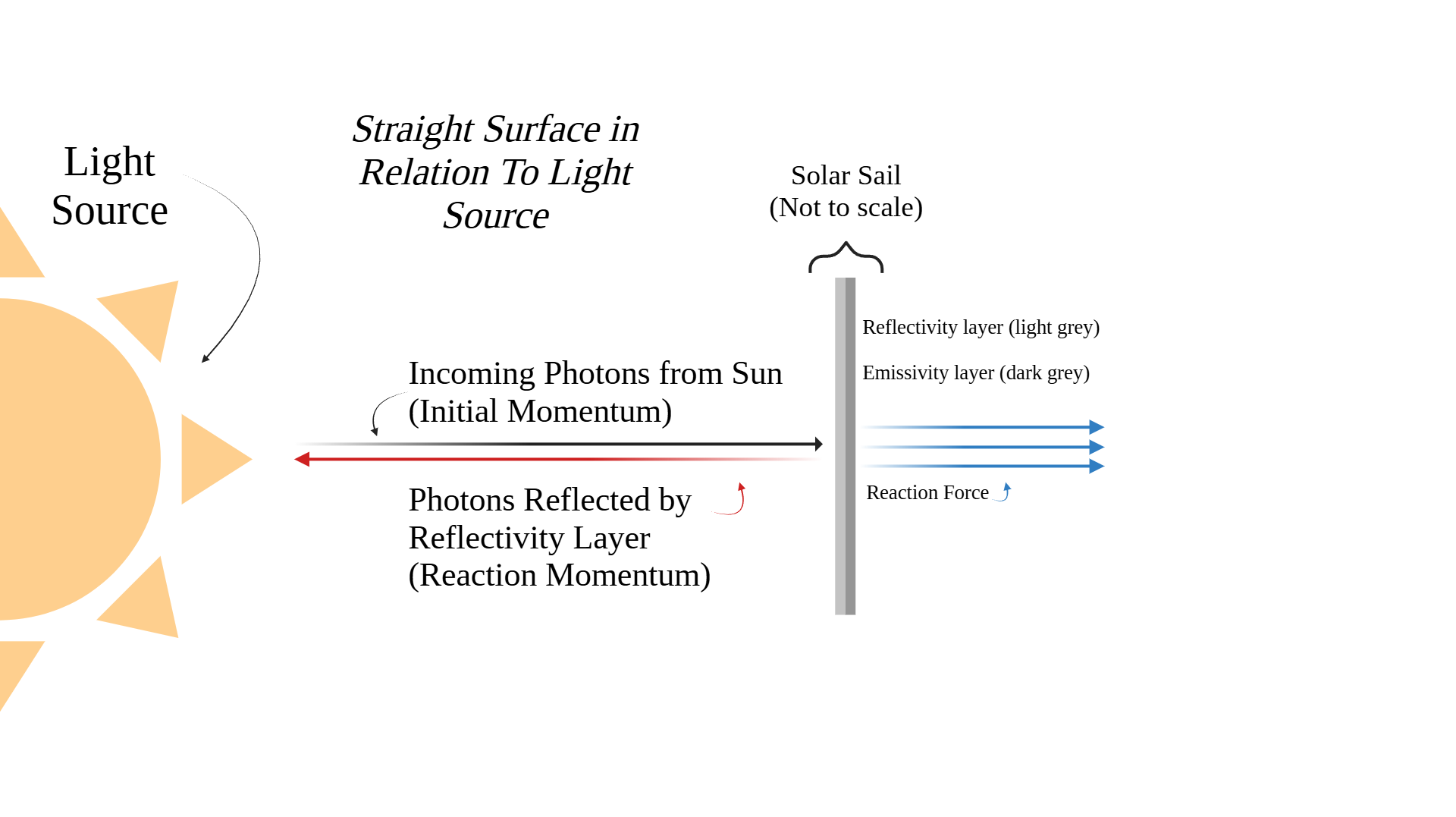
Figure 1.3.1: Straight Surface in Relation to Light Source (Created in https://BioRender.com)
The figure above features two photon paths. One path for initial momentum, (black) and the other for reaction momentum (red). The path for initial momentum is seen approaching from a light source, or in this case, the Sun. The initial momentum describes the momentum of the photons which collide with the solar sail, transferring momentum and exerting a force on the spacecraft. While light has virtually no mass, it has an incredibly high velocity. This velocity is what enables photons or light particles to have momentum. This is the basic principle of how light can propel an object. However, we can effectively double this process through the use of a perfectly reflective material (Miller, 2015).
Solar sails have three main components; the emissivity layer (dark grey), reflectivity layer (light grey), and payload (Miller, 2015). The layer in a solar sail membrane responsible for propulsion is the reflectivity layer. Due to the 3rd law of Newtonian physics, which states that for every action, there is an equal and opposite reaction, reflected photons can also use their reaction momentum to contribute to the propulsion of a solar sail. The reflectivity layer functions by reflecting incoming photons from a light source (such as the sun). When incoming photons from a light source bounce off the reflectivity layer, they also transfer their momentum to the solar sail (Miller, 2015). We can see the reaction momentum in figure 1.3.1 as the red path. Both the initial and reaction momentum contribute to the reaction force, allowing solar sails to efficiently propel themselves through space. Over time, this acceleration allows solar sails to gain significant velocity. However, photons that are absorbed (not reflected) are radiated through the emissivity layer as infrared light or heat away from the incoming light source (Miller, 2015). While this emission does have a small negative impact on the velocity of the sail, it is negligible, and is crucial to maintain stable solar sail temperatures.
Below, we can see a diagram of the reflectivity scale, which represents the reflectivity of different substances on a linear scale. Perfect absorbent materials (0.0) absorb all incoming light. Subsequently, perfect reflectants (1.0) reflect all incoming light (Miller, 2015). However, both perfect absorbent and perfect reflectant materials are physically impossible because of entropy, meaning both processes cannot be 100% efficient. "Perfectly" absorbent materials will reflect some light, and "perfectly" reflective ones will absorb some light.
The common reflectivity values of solar sail membranes (0.88 10 0.99) can be seen below, roughly highlighted in blue. These values vary by material. A suitable material for a membrane varies on many factors, and reflectivity is a large one. These values are important to understand as they play a key role in calculating momentum, force, and velocity.
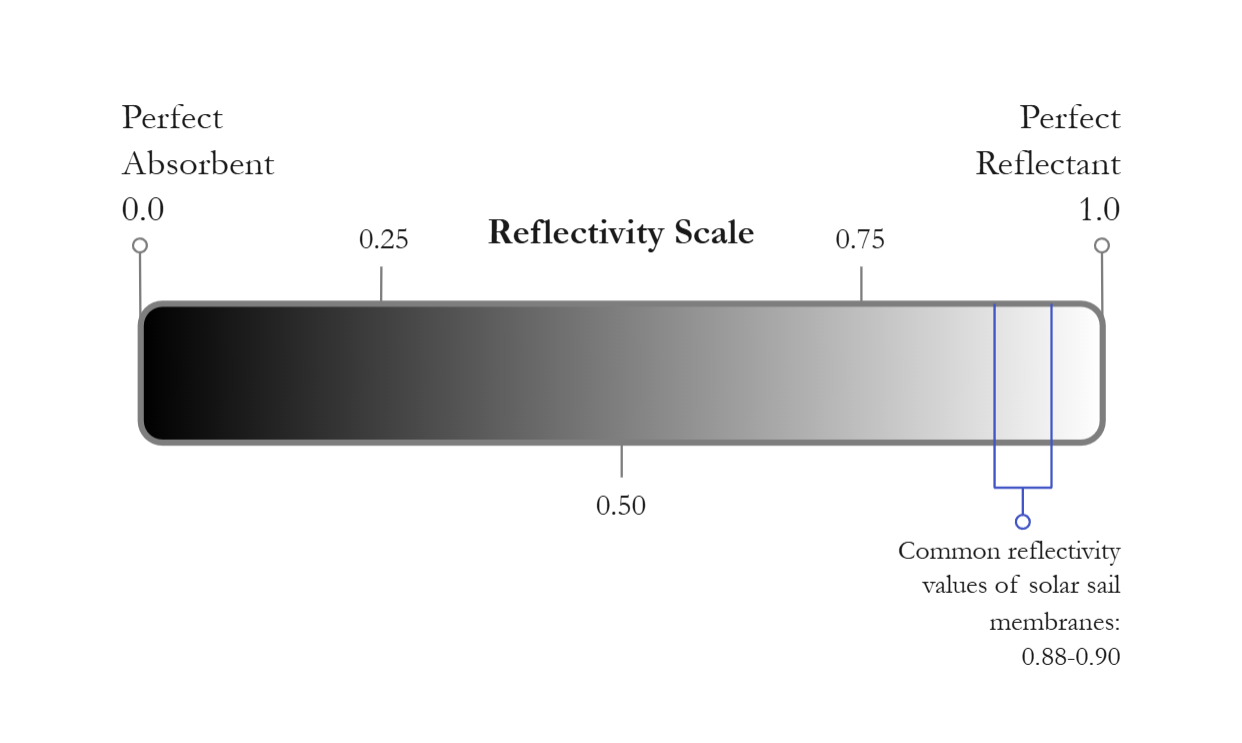
Figure 1.3.2: The Reflectivity Scale
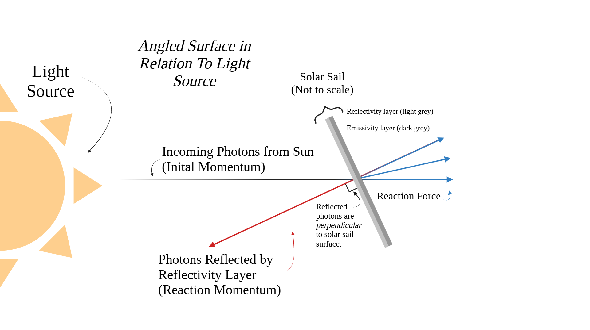
Figure 1.3.3: Angled Surface in Relation to Light Source (Created in https://BioRender.com)
Before we begin to understand the calculations for determining momentum, force, and velocity, we should begin to understand how the basic principles of light-based propulsion change when surfaces in relation to the light source are angled. The above figure (1.3.3) is a diagram of how photon paths change when reflected at an angle. Similar to the first diagram, it features a light source, initial momentum path (black), and reaction momentum path (red). However, the solar sail here is slanted, causing the reaction momentum path to change course. Notice how the reflected photons are always perpendicular to the surface they were reflected from (the solar sail membrane). We can see how both the initial momentum photon path and reaction momentum photon path have corresponding reaction forces. Initial momentum creates a reaction force that continues straight ahead, while the reaction momentum path has a reaction force that is angled, also perpendicular to the solar sail. These two forces combine to propel the solar sail in an angled path as opposed to a linear one (Miller, 2015).
Now that we understand the basic principles of solar sail propulsion, we can begin to understand how to calculate it, and how to maximize our ability to generate thrust through photon-based propulsion. Solar sails operate on the principle of photon momentum transfer. When photons from sunlight strike the sail's reflective surface, they impart momentum, creating a reaction force that propels the spacecraft. Although photons have no mass, their high velocity enables them to carry momentum, as described by the equation:
Momentum Of a Photon With an Absorbent Surface (Miller, 2015):
P = 1E/C
Where:
- P is equal to the momentum of the photon.
- E is equal to the energy of the photon.
- C is equal to the speed of light in a vacuum (a constant: 3.00•108m/s).
However, this equation changes when we factor in the reflectivity of a surface. As seen earlier, the average reflectivity values for solar sail membranes were roughly 0.88-0.90. For a reflective surface, the momentum transfer is enhanced. If the sail has a reflectivity coefficient K, the equation becomes:
Momentum Of a Photon With a Reflective Surface (Miller, 2015):
P = (1+K)E/C
Where:
- P is equal to the momentum of the photon.
- K is equal to the reflectivity value of the surface (in this case, 0.89).
- E is equal to the energy of the photon.
- C is equal to the speed of light in a vacuum (a constant: 3.00•108m/s).
We can see how the equation is affected through the reflectivity. If the reflectivity of our surface was perfect, then we would essentially double the energy of the photon, therefore doubling the momentum transferred onto the solar sail. However, we cannot have a perfectly reflective surface, but having a solar sail with a surface that is the most reflective will allow us to generate the most force. For example, a sail with a reflectivity of 0.89 transfers 1.89 times more momentum than a perfectly absorbent surface. In tandem with the diagrams earlier, we can understand how this increased efficiency allows solar sails to achieve significant acceleration over time.
Force Created by Momentum Of a Photon (Miller, 2015):
The force generated by a solar sail can be calculated using the equation:
F = I(1+K)/C
Where:
- F is equal to the force of the solar sail.
- I is equal to the solar intensity (watts/m2).
- K is equal to the reflectivity value of the surface.
- C is equal to the speed of light in a vacuum (a constant: 3.00•108m/s).
Knowing the equation for momentum, we can begin to see the similarities between the two equations. Both need the reflectivity value of a solar sail. The momentum equation requires the energy of the photon while the force equation requires solar intensity instead. We can apply this knowledge to calculate the velocity of a solar sail.
Calculating The Velocity Of a Solar Sail (Miller, 2015):
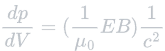
Where:
- dp is equal to the change in momentum (see momentum of a photon with a reflective surface).
- dV is equal to the change in volume of light interacting with the sail.
- μ0 is equal to the permeability of free space [a constant: 4π•10-7N/A2 (newtons per ampere squared)].
- E is equal to the electric field component of light.
- B is equal to the magnetic field component of light.
- C is equal to the speed of light in a vacuum (a constant: 3.00•108m/s).
To understand how this equation can be used to calculate velocity, we must dissect it into smaller parts to get a greater, comprehensive understanding of what is occuring. Describing the equation this way will allow us to rearrange it to determine values for dv (velocity).
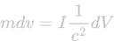
According to Newton's second law, the change in momentum is equal to mass times velocity. Therefore:
dp = mdv
Where:
- dp is equal to the change in momentum.
- m is equal to mass.
- dv is equal to change in velocity.
Furthermore, in order to calculate the change of volume of light interacting with the solar sail, we can use the following equation:
dV = LA
Where:
- dV is equal to the change in volume of light interacting with the sail.
- A is equal to the area of light interacting with the solar sail (essentially area of the solar sail, m2)
- L is equal to the length of the beam of light interacting with the sail (L = ct).
Finding the length (L) can be determined by multiplying the speed of light with the time in seconds (L = ct), giving us the distance the light has travelled. This works because light travels a set, constant speed in a vacuum (3.00•108m/s). If we know how many seconds it has travelled, then we know how far it has travelled. Assume you roll a ball at a steady speed of 2m/s. If the ball travelled for two seconds, it would have travelled four meters. The same principle applies to light. By multiplying the length with the area of a solar sail, this equation allows us to accurately define how much light is interacting with the solar sail.
We can further simplify the initial velocity equation using this equation for solar intensity:
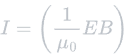
Where:
- I is equal to the solar intensity (watts/m2).
- μ0 is equal to the permeability of free space [a constant: 4π•10-7N/A2 (newtons per ampere squared)].
- E is equal to the electric field component of light.
- B is equal to the magnetic field component of light.
The electric and magnetic field component of light:
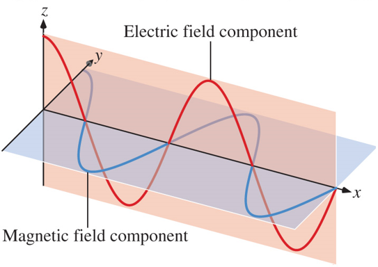
Figure 1.3.4: The Electric and Magnetic Components of Light (Dornshuld, n.d.).
The electric and magnetic field component of light describes light as an electromagnetic wave: it consists of two components, the electric and magnetic. These components are waves, perpendicular to each other. They allow us to describe the energy of light. The above figure visualizes how light travels as a wave. The two waves always have the same frequency and wavelength and depending on their wavelength, their energy changes (NASA, 2010).
Conveniently, we can ignore these aspects of light. As described above, we can substitute solar intensity. With these substitutions, we can simplify our initial equation to solve for velocity.
Initial Equation:
Rearranging The Equation:
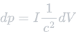
As aforementioned, we can substitute EB and μ0 for solar intensity, I. This allows us to simplify our initial equation to the following:

Using this equation, we can begin to introduce the required variables in order to solve for velocity. First, we must isolate the change in momentum, dp, so we can later substitute it for mdv. We can do this by rearranging the equation to move dV to the right (multiply by dV). This gives us the following:
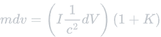
Now we can introduce velocity. Earlier, we learnt that dp = mdv. Knowing this, we can substitute dp for mdv, which we can further isolate into velocity later. We must introduce four more variables before we can solve.
In figures 1.3.1 through 1.3.3, we demonstrated how the reflectivity of a surface can affect the momentum, force, and therefore velocity it gains from incoming photons. In order to maximize our solar sail's efficiency, we will ensure the membrane we use is the most reflective as possible. We will represent the reflectivity value of the solar sail with K.
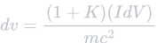
We can now further isolate velocity by dividing by mass. This will move mass to the right. The rearranged equation is as follows:
Finally, we need to substitute dV (change in volume of light) with the variables L and A, expressed through the equation dV = LA. L can be further split into ct, described earlier with the equation L = ct. This leaves us with the variables c, t, and A. Where c is the speed of light, s is the time in seconds, and A is the area of the solar sail (m2). This gives us our final equation for velocity.
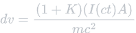
Where:
- dv is equal to change in velocity.
- A is equal to the area of light interacting with the solar sail (essentially area of the solar sail, m2).
- I is equal to the solar intensity (watts/m2).
- c is equal to the speed of light in a vacuum (a constant: 3.00•108m/s).
- K is equal to the reflectivity value of the surface.
- m is equal to mass.
- t is equal to the time (seconds).
If we were to launch a probe starting from Earth, assuming it had a mass of 70lbs and one large square solar sail with the dimensions 124mx124m (15376m2), (the same dimensions as the Sunjammer, a cancelled solar sail mission), and a perfectly reflective surface, then we can calculate how long it would take for the probe to reach the following speeds:
Velocity Over Time - (Miller, 2015)
| Velocity | Time | Distance Travelled |
| 1 m/s | 3.793 min | 0.227561242 km |
| 50 m/s | 3.16 hours | 568.935291 km |
| 100 m/s | 6.32 hours | 2275.805537 km |
| 500 m/s | 31.61 hours | 56894.9775 km |
| 1000 m/s | 63.21 hours | 227579.942177 km |
By understanding how solar sails can exponentially increase their velocity over time, we can see how they are an effective candidate for deep-space exploration, surpassing other traditional methods of propulsion. This makes solar sails a plausible transport method for a mission to the solar gravitational lens.
1.4.Design of Solar Sails
Solar sails come in three primary designs, each with unique advantages and challenges. This project focuses on the square solar sail due to its simplicity, effectiveness, and proven track record.
| Type of Solar Sail | Image | Deployment Method | Rationale |
| Square Sail | 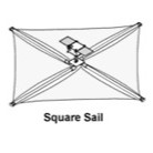 |
Square sails are three-axis stabilized, meaning their structure supports the sail membrane in all three axes without rotating (SolarSailWiki, n.d.). Similar to a kite, this structure spreads out the membrane and holds it stiff, ensuring adequate light capture. This is done using extendable boom arms, which deploy four triangle-shaped masks that create a larger, uniform, square shape (SolarSailWiki, n.d.). | The square sail is the most favored and popular due to its simple, effective design. A large advantage of the square shape is that it maximizes surface area, allowing the sail to generate high amounts of thrust from photons, while also minimizing hot spots produced by incoming thermal radiation from the sun (Miller, 2015). This shields the rest of the spacecraft and prevents it from overheating. However, the boom arms needed for deployment make this design heavier than the other two. |
| Heliogyro Sail | 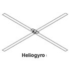 |
This design was developed by NASA's jet propulsion laboratory (JPL) in the 1970s. The deployment method for this sail has a stronger structure compared to the square sail by harnessing centrifugal force (Miller, 2015). Unlike the three-axis stabilized design of the square sail, this design is spin-stabilized. By rotating, this design deploys its blades from rollers, which extend into long, flat surfaces, eliminating the need for supports (SolarSailWiki, n.d.). This is made possible through centrifugal force, the same phenomena that prevents water from spilling out a spinning bucket. The number of blades can be more than four. They are attached to the center using multiple wires (SolarSailWiki, n.d.). | The heliogyro's blades can be controlled similar to a helicopter, enabling this design to adjust its pitch and cycle to redirect solar pressure and maneuver itself (Miller, 2015). Due to its alternative method of deployment, this design has a stronger structure, however, the rotation has to be sustained in order for the blades to keep their shape. The shape of the blades means this design's surface area is much less than the square or spinning disk sails, making it less feasible for long term travel where maximum photon collection is needed. |
| Spinning Disk Sail | 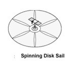 |
The spinning disk sail was also developed by JPL and follows a concept similar to the heliogyro sail (Miller, 2015). It uses only rotation and light, thin tethers to ensure its masks are spread out. Furthermore, it features small gaps in its design to maximize its surface area. This allows it to have a surface area similar to the square sail. | By achieving a surface area similar to the square sail while also staying light, the spinning disk sail is a strong candidate. However, it also requires constant spinning to keep its centrifugal force strong enough to suspend itself, and it has not been tested in space. |
From the above table, we can conclude that the square sail's balance of efficiency, durability, and simplicity makes it the most suitable design for SGL missions. Its ability to generate high thrust while protecting the payload from solar radiation ensures its viability for long-duration space travel. However, combining features of the sails may prove to be a better solution. A design that uses the deployment of a heliogyro sail while also using large amounts of surface area, like a square solar sail, may prove to be the most effective for this intrasolar mission.
The following are 3D models of potential solar sail designs.
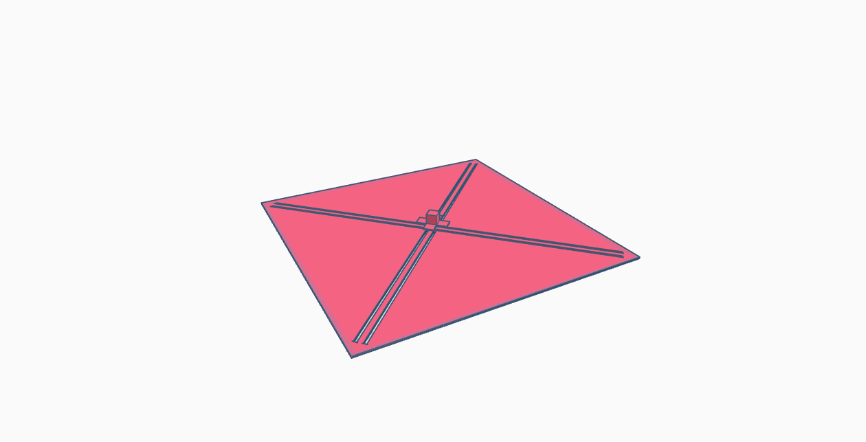
Figure 1.4.1: 3D Model of a Square Solar Sail

Figure 1.4.2: 3D Model of a Heliogyro Solar Sail
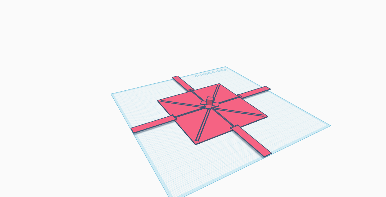
Figure 1.4.3: 3D Model & Design of a Hybrid Solar Sail (Subject To Change)
As seen above, a solar sail with both qualities of a square and heliogyro design may prove to be the most scalable. The hybrid design I present takes advantage of these benefits. In theory, a sail with this design would have greater maneuverability through its blades, able to be angled like that of a helicopter, enabling greater attitude control. This hybrid design would differ from traditional heliogyro sails: Instead of the entire spacecraft rotating, only the blades would spin, passively powered by solar radiation. This would allow the sail to minimize torque on the center while keeping the maneuverability of the heliogyro's blades.
Benefits of This Design:
The design I propose for a mission to the SGL uses characteristics of both heliogyro and square solar sails. This hybrid design allows for:
- Greater maneuverability.
- Fine-tuned adjustments to course.
- Dynamic adjustments to blade angles, allowing for efficient propulsion to be sustained at all times (this also means the blades can adjust their angle if interstellar objects impact the sail).
- Counteraction to instability by adjusting blade angles, potentially fighting back against wobbles or unstable parts of the spacecraft.
Two key elements must be considered for a solar sail in deep-space travel: Long-term durability and adaptability. A mission to the SGL implies a long time in deep-space, potentially multiple decades. While this time can be cut short using solar sails, they still need to be reliable enough to survive the years in space. This hybrid design incorporates the most reliable design yet; the square solar sail. In tandem with this durability, the design must also have the ability to adapt. Space travel is unpredictable, and therefore, it is essential the solar sail we use contains an adaptable element that allows it to compensate for future instabilities or changes during intrasolar travel. This hybrid design takes advantage of the heliogyro's blades to achieve this, allowing for dynamic changes throughout.
This design would function using a combination of tethers, boom arms, electromechanical components, solar radiation, and centrifugal force. The deployment would include two parts: the square sail and the blades. The square sail and blades would be deployed using their respective deployment methods (three-axis stabilization and spin stabilization), using boom arms and tethers. The blades would initially extend using motors to rotate them and stay extended by tilting to an angle sufficient enough to allow for photons to push on the blades and cause them to rotate. This rotation would keep the centrifugal force strong enough to keep the blades extended, keeping the design energy-efficient. These blades would have their angles fine-tuned sparingly using small motors that can rotate, allowing for minor corrections. However, solar pressure should passively adjust the angles without the need for mechanical components, allowing for longevity. Therefore, even if the mechanical components fail, the blades would still be able to rotate given they are angled correctly and are facing a source of light.
2.Solar Gravitational Lensing (SGL)
Imagine the possibilities that would open up if direct imaging of exoplanets was possible. Currently, the only images of planets that we have are those within our solar system. Imaging another world within another solar system would be an incredible revolutionary feat. Not only would it revolutionize the realm of telescopy and astronomy, but it would alter the way humans as a society views the universe and world. We could be opened to the fact that we may not be alone.
With a newfound understanding of solar sail design, physics, and benefits compared to other propulsion systems, we can begin to understand how to harness solar gravitational lensing to directly image exoplanets, using solar sails as an effective method of transport. These sections will highlight the physics of solar gravitational lensing, drawbacks, deformities and restoration of an image, observational methods, and the exoplanet a potential mission could image. Using this knowledge, we will be able to conclude if an SGL in combination with solar sails is a viable form of technology capable of revolutionizing telescopy.
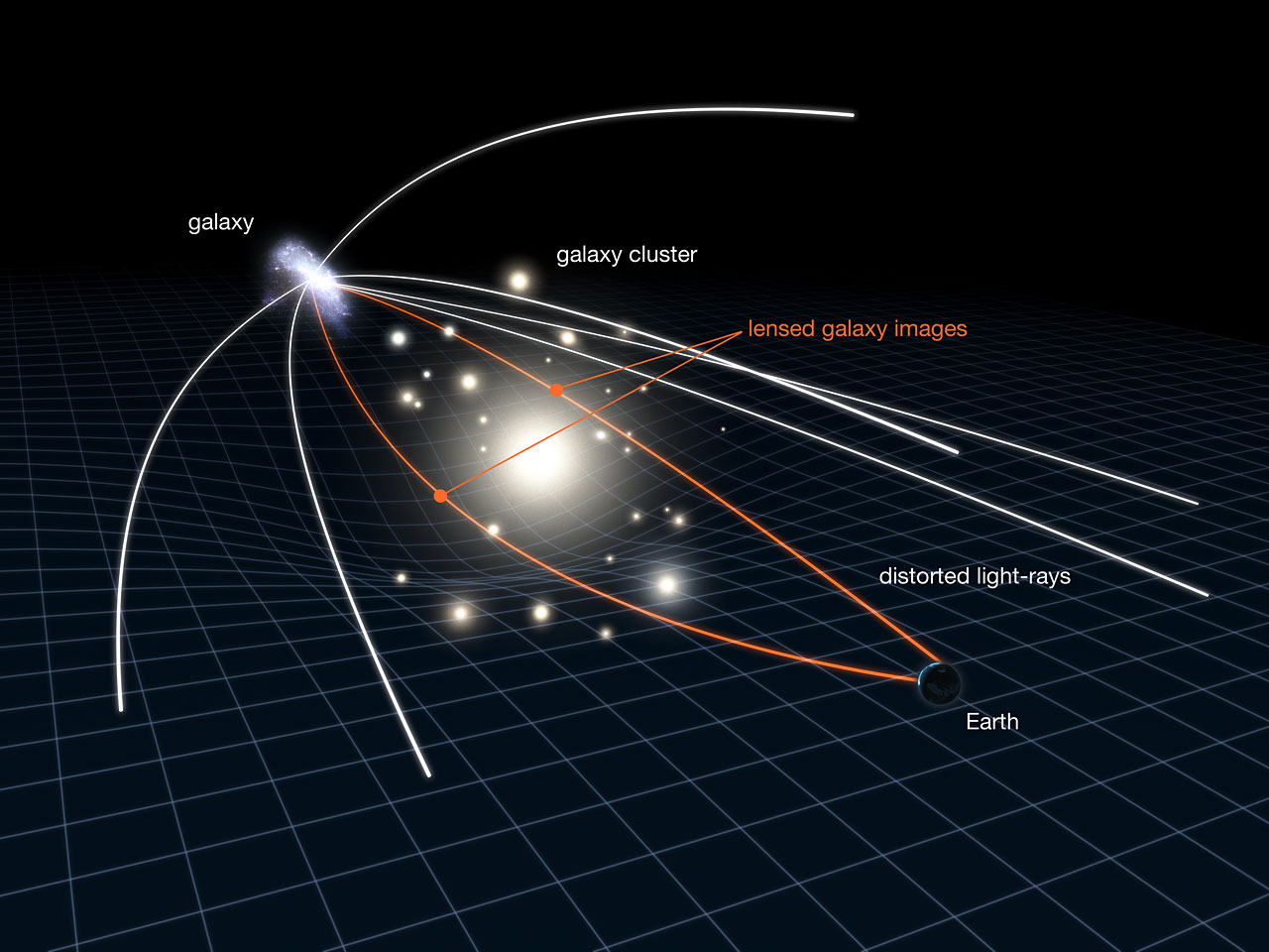
Figure 2.1: A Visualization Of Gravitational Lensing In Galaxies (NASA et al., 2011).
2.1.The Physics of Solar Gravitational Lensing
Brief Information:
Solar Gravitational Lensing (SGL) is a complex method to magnify an image behind a gravitational body in order to produce high resolution, detailed images. Most notably, this technology has significant applications in the realm of astrophotography and specifically, the imaging of exoplanets. SGLs are an incredibly beneficial and revolutionary method of exoplanet imaging. They possess the power to directly image exoplanets, greatly increasing magnification. However, the distortions caused by heavy gravitational lensing pose great challenges. (Turyshev, 2018)
Einstein's general theory of relativity states that gravity warps spacetime, including light. This means, similar to a refractive lens, large gravitational bodies can express refractive properties and "bend" light, focusing and amplifying it to a single point. Gravitational lensing has been observed and recorded before in many cases, most notably in far away galaxies which act as gravitational lenses for background galaxies. (Turyshev, 2018)
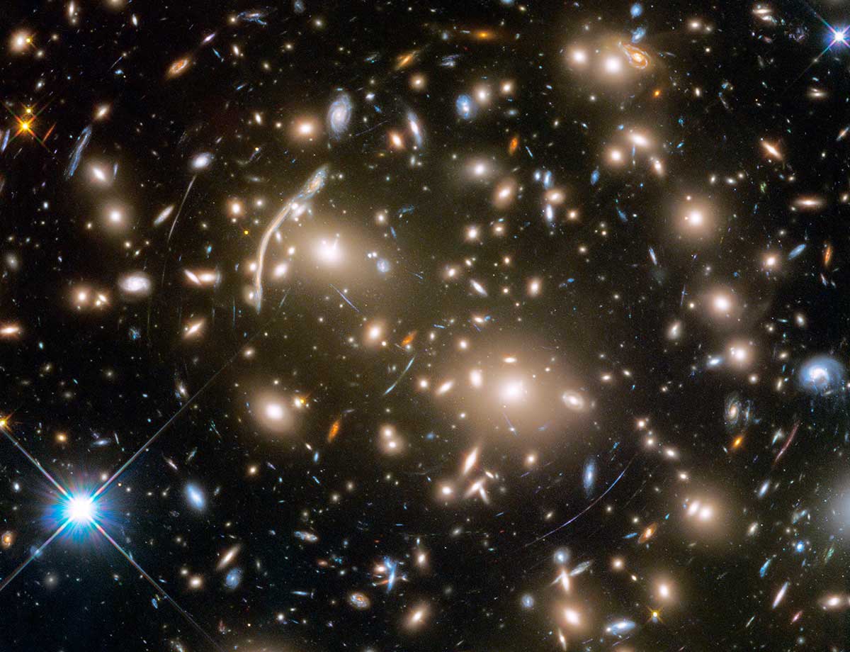
Figure 2.1.1: Galaxy Cluster Gravitational Lensing Captured By Hubble (NASA, 2022).
The above image features galaxy cluster Abell 370 (~4 billion light-years away) warping and distorting images of remote galaxies behind it, evident through the blue "arcs" of light. Directly, the Hubble space telescope would never see the galaxies behind Abell 370, as they are too far and their light is too weak. Gravitational lensing is the reason these arcs of light are visible, acting as a huge lens magnifying the background galaxies, even duplicating the image of them multiple times. This phenomenon is applicable in our solar system, and is the fundamental basis of an SGL (NASA, 2022).
In our solar system, only one celestial body has the incredible mass (and therefore, gravity) required for gravitational lensing: the Sun. However, to utilize the SGL, a mission must be placed at a minimum distance of ~550 AU (astronomical units - distance from Earth to Sun), which is the start of the focal line where light bent by the Sun converges. Despite these demanding requirements, SGLs open awe-inspiring possibilities. Successfully operating a mission at the distance of the SGL would prove that deep space and future interstellar travel is possible. Furthermore, SGLs have key benefits that provide incredible brightness amplification (factor of 6,400) and a groundbreaking angular resolution of ~10-9 arcsec (one arcsec is 1/3600th of a degree). Angular resolution is the ability of an imaging device (such as the eye) to distinguish between two points of an image. The smaller the number, the more precise you are able to image an object (higher resolution). In the case of telescopy, an angular resolution of ~10-9 arcsec is incredible. To understand how powerful an SGL is, imagine a 1m diameter telescope is placed 750 AU from the Sun. At that distance, an SGL would have the light collecting area equivalent to a telescope with a diameter of ~80 km. A telescope of that magnitude would be able to produce high resolution spectroscopy and imaging of an exoplanet (Turyshev, 2018).
Physics Of Light Bending:
The gravitational deflection angle of light describes how a light particle's path will be bent by spacetime. This can be expressed as: (Landis, n.d.)
θ = (4GM/c2)(1/r)
Where:
- θ (Theta) is equal to the deflection angle.
- G is equal to the gravitational constant.
- M is equal to the mass of the body deflecting the light (the Sun).
- c is equal to the speed of light.
- r is equal to the impact parameter (the distance which the rays pass the Sun instead of hitting its center).
This equation allows us to understand the relationship between light, mass, and speed. As evident in the equation, the larger the M, mass (more gravity & warping), the more the light will be warped. The closer the light approaches the object, r, the more the light will be pulled on and therefore the more it will be bent. Finally, the faster the speed, (in this case the speed of light), the less bending occurs. This is why we need objects with large mass and gravitational influence to make use of bent light. However, despite the Sun's enormous mass, the distance needed to capture bent light is far.
The minimum distance for an SGL can be calculated by:
F = (4GM/c2)-1r2
OR
F = r2c2/4GM
Where:
- F is equal to the distance to the SGL focus.
- G is equal to the gravitational constant.
- M is equal to the mass of the body deflecting the light (the Sun).
- c is equal to the speed of light.
- r is equal to the impact parameter (the distance which the rays pass the Sun instead of hitting its center).
This equation describes the minimum distance a telescope has to be to take advantage of an SGL. Inserting the radius of the Sun gives us a minimum focal distance, where focused rays skim the surface of the Sun. This distance is ~550 AU (Landis, n.d.). As long as you are beyond this distance, you will be on the focal line.
The below figure provides a diagram representing the path of light through the bending from the Sun's gravity:
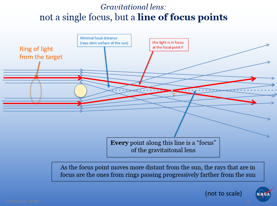
Figure 2.1.2: The Line of Focus Points On a Gravitational Lens (Landis, n.d.).
Above, we can see how the path of light is bent (as described by the gravitational deflection angle equation) to focus light to a single point. We can see how at the minimum focal distance, the light skims the surface of the Sun, and beyond the focal distance there is a "line" of focus points. The farther a focal point is, the rays in focus are progressively farther than the Sun. In other words, the rays passing the Sun converge at different points, because the closer a ray of light is to the Sun, the more it is bent. Consequently, the farther a ray is, the less it is bent, meaning the rays will converge at a farther distance. This means the focal point for an SGL is not set to one distance; depending on the object being imaged, the distance from the Sun changes.
2.1.2.Image Distortions and Restoration
A telescope on the focal line (FL) would not see a clear image of the exoplanet: Rather, it would see the exoplanet as an annulus around the Sun, a distorted image. This is called an Einstein Ring. Despite intense magnification, the light of this Einstein ring would still be far dimmer than the Sun. This is why a telescope at the SGL would require a coronagraph (essentially an artificial eclipse) sufficient enough to block light from the Sun's corona, making exoplanet light detectable. A coronagraph blocks the light of the Sun, a star, or other intense source of light so that dimmer, nearby objects can be easily observed. A coronagraph for an SGL telescope would be modest, requiring a suppression factor of ~106 (Turyshev, 2018). Furthermore, due to the limitations of our technology, a telescope at the SGL would most likely be a single-purpose telescope. In order for a spacecraft at the minimum distance for the FL to image a target one degree away, it would have to move laterally 10 AU. This is the equivalent of the distance from the Earth to Saturn. A spacecraft that can efficiently travel that distance would not be feasible, meaning the telescope would only be able to image one target. However, the results would surpass the capabilities of any telescope we have to date (Landis, n.d.). An SGL-powered telescope opens up the possibilty of direct Earth-sized exoplanet imaging and spectroscopy with a resolution of 1000x1000 pixels (10km2 of exoplanet surface per pixel) up to ~98 lightyears away (30 parcsecs) (Turyshev, 2018). Most other NASA exoplanet imaging missions hope for getting a single pixel to study an exoplanet. In contrast, an SGL would provide thousands of pixels, surpassing countless other exoplanet concepts. It is important to note that while an SGL would provide higher resolution, there are still drawbacks to consider caused by blur. The image below does not 100% accurately represent the image an SGL would produce, rather it provides a rough sense of scale. While the image produced by an SGL would be similar, it would contain blur and visible, defined pixels.
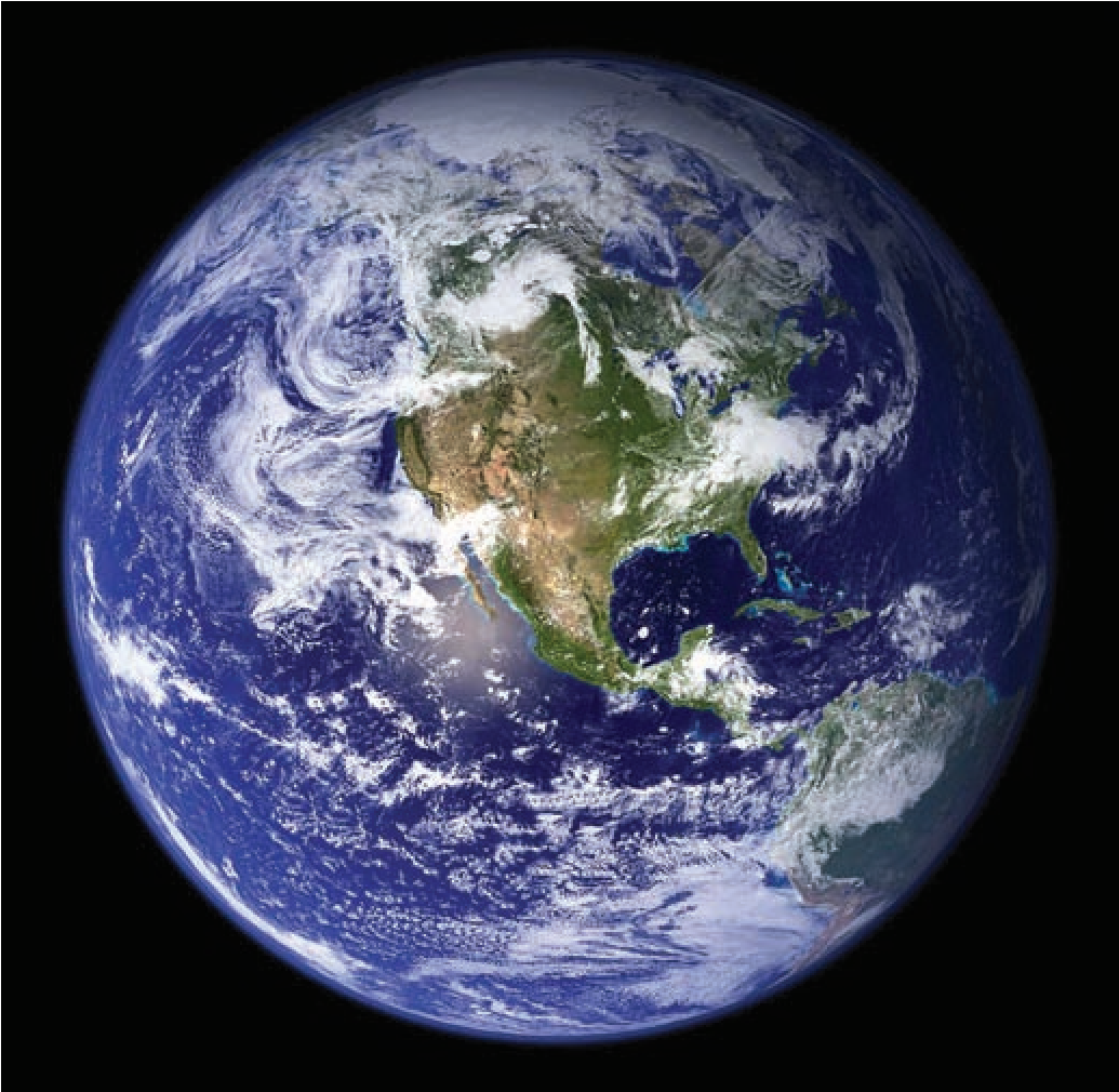
Figure 2.1.3: An Image of Earth at 1000x1000px (Turyshev, 2018).
An SGL is not a simple lens or telescope. Rather, it is a system that requires precise planning, timing, and steps (Landis, n.d.). As previously mentioned, the focused light of an SGL produces a smeared out image of the exoplanet resembling an annulus, or Einstein ring. These distortions must be reversed before we can properly view the image.
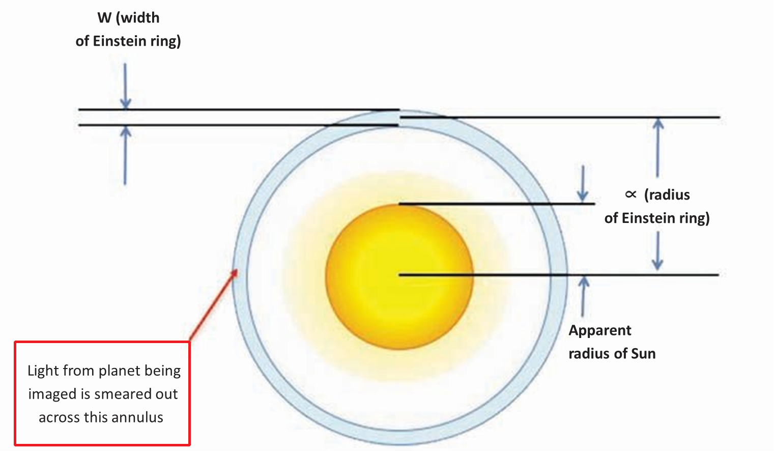
Figure 2.1.4: View of Einstein Ring from SGL Focal Line (Landis, n.d.).
The above diagram visualizes the view of an Einstein ring from the perspective of a telescope at the SGL FL (not to scale). As seen above, the light of the planet is smeared across an annulus that surrounds the Sun. To calculate the magnification factor, we must divide the (angular) area of the Einstein ring/annulus by the (angular) area of the planet without a lens (Ao/Ai) (Landis, n.d.). This gives us the following:
Magnification Factor = Ao/Ai
Ao/Ai = (πar)/(πa2/4) = 4r/a
Where:
- Ao is equal to the area of the annulus (2πrw, but w = a/2, so Ao = πar).
- w is equal to the width of the Einstein ring (as seen in figure 2.1.4).
- r is equal to the angular/apparent radius of the Einstein ring.
- Ai is equal to the angular area of the source.
- a is equal to the angular diameter of the source.
This allows us to define how an SGL magnifies its target. However, in order to make use of this magnification, we must understand how to deconstruct the distortions caused by an Einstein ring.
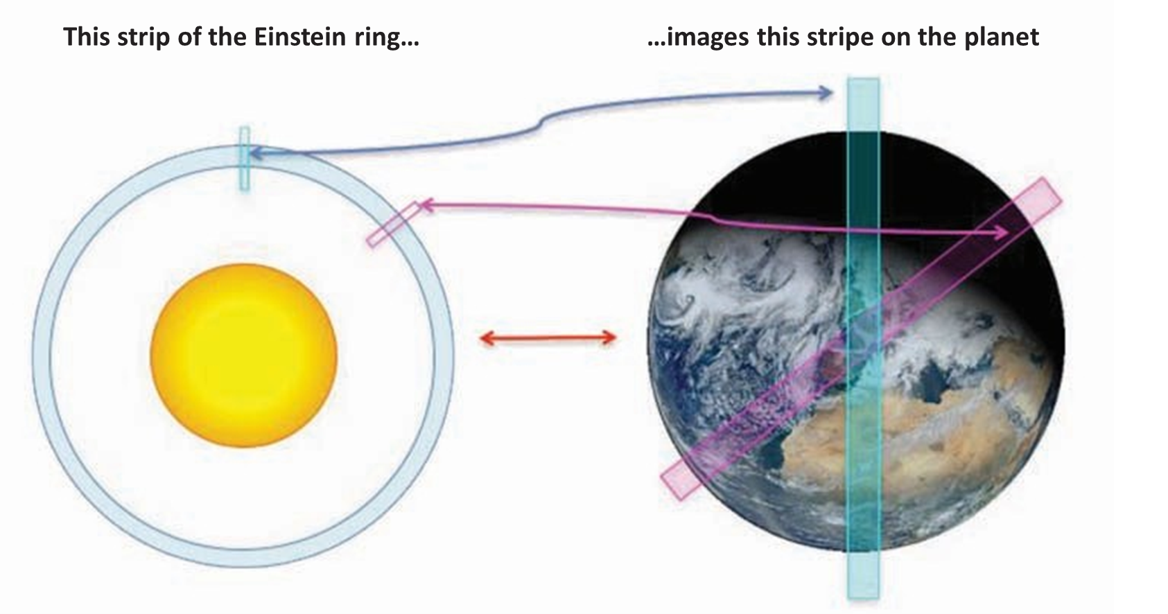
Figure 2.1.4: Mapping of Einstein Ring Strips to Exoplanet (Landis, n.d.).
The above figure shows how the mapping of Einstein Ring Strips translates to an actual exoplanet. Each "strip" on the Einstein ring translates to a "stripe" on the actual exoplanet. Notice how each stripe on the Einstein ring crosses/includes the center point. This gives us a basis for decontructing image distortions. The strips at each part of the Einstein ring provide a stripe of the image of the planet at a certain angle (notice how the purple strip is the same angle on the exoplanet). By looking at multiple strips of the Einstein ring, we could develop enough data to stitch together an image of the planet. Furthermore, we would only need to image half of the Einstein ring. If we were to continue the pattern seen in figure 2.1.4, then eventually we would image strips that overlap. In other words, the same strip on the exoplanet repeats every 180 degrees. To reconstruct the exoplanet's image, advanced computational models and algorithms are required to reverse these distortions, which could potentially mean prolonged reversal times (Landis, n.d.).
2.2.Benefits And Drawbacks
Comparisons To Other Telescopes (ESO and JWST):
As discussed above, a mission to the focal point of the SGL would require much planning and preparation. However, there are some benefits and drawbacks to consider. Due to the nature of an SGL, it would boast image quality capabilites unprecedented before, as aforementioned, it would have the capability of producing exoplanet images 1000x1000 pixels in resolution. In comparison to the best exoplanet images we have created by JWST and ESO, an SGL far surpasses their capabilities.

Figure 2.2.1: First Image of a Multi-Planet System Around a Sun-like Star (ESO & Bohn et al., 2020).
The above figure depicts the first ever image of a multi-planet system around a star like our Sun, captured by the European Southern Observatory's (ESO) SPHERE instrument. The two exoplanets of the star system orbit the star TYC 8998-760-1, seen in the center and bottom-right of the image; TYC 8998-760-1b and TYC 8998-760-1c respectively, as highlighted by the arrows (ESO & Bohn et al., 2020). The other dots in the image are background stars. The ESO SPHERE can reach an angular resolution up to 20 milli-arcseconds (0.020 arcseconds) (ETH Zurich, n.d.). In contrast with an SGL, which, as mentioned earlier, can reach an angular resolution of ~10-9 arcseconds (0.000000001 arcseconds), the ESO SPHERE pales in comparison. Furthermore, SGLs have the capability to surpass the JWST (James-Webb Space Telescope).
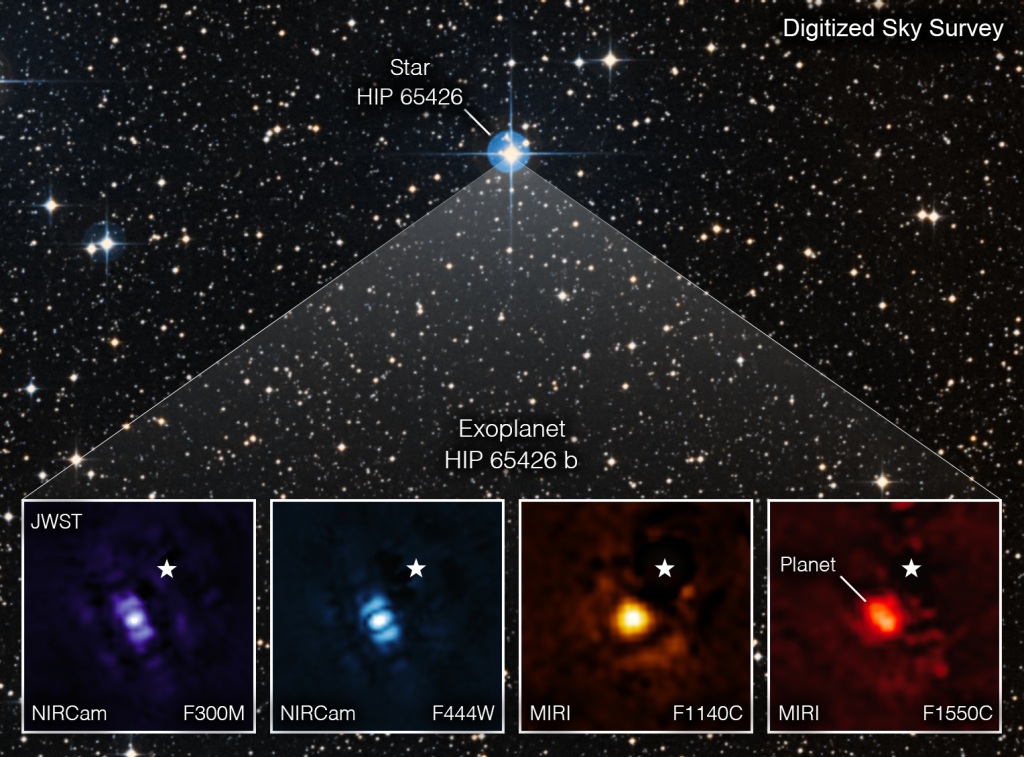
Figure 2.2.2: Exoplanet HIP 65426 b Imaged by JWST (Fisher & NASA, 2022).
Above, we can see the exoplanet imaging capabilities JWST possesses. These are images of the same exoplanet in different infrared bands (3-15.5 micrometers) (Fisher & NASA, 2022). JWST has an angular resolution of ~0.1 arcseconds. Again, an SGL-powered telescope would have a much higher angular resolution, which would allow it to surpass JWST. It is important to note that JWST sees entirely in infrared. A telescope at the SGL would most likely see in infrared and visible light. This is because infrared light is beneficial for in-depth analysis, but visible light would allow us to discern surface features (due to its shorter wavelength). Infrared light was primarily chosen for JWST due to its longer wavelength, allowing it to pass through dense regions of gas and dust with minimal scattering and absorption (NASA, 2010). For the same reasons, an SGL-powered telescope would most likely use infrared imaging instruments as well.
Benefits:
An SGL has major magnification and image brightness benefits. In 2.1, it was defined how an SGL magnifies an image and the calculations for it. Starting at the minimum focal line distance (~550 AU), the light bent by the Sun forms a folded caustic (see figure 2.1.2), which magnifies the light significantly. For λ = 1 µm (λ → lambda, which represents the wavelength of light -- 1 µm/micrometer falls within the infrared spectrum), the magnification produced by an SGL would be 1x10¹¹, or one hundred billion (Turyshev, 2018). This would be with the resolution mentioned earlier, [~10-9 arcseconds, also known as one nano-arcsecond (nas)]. Combined with the extreme angular resolution, an SGL could potentially produce images of exoplanets in 1000x1000 pixel resolution (see figure 2.1.3).
Along with the extreme magnification capabilities, an SGL also offers immense image brightness. For example, the amount of light collected from an exoplanet 10 lightyears away would be increased by the SGL to a factor of 6,400. In other words, a telescope with a diameter of 1 meter using the SGL would collect the same amount of light as a regular 80 meter diameter telescope.
Drawbacks:
Despite these benefits, SGLs face significant drawbacks. As aforementioned, the deconstruction of Einstein rings is a significant challenge. While in theory it is possible, undoing the distortions by an Einstein ring will still be difficult. Furthermore, blur is another drawback that must be addressed. Blur, or loss of focus, is defined as the amount which the focus deviates from an ideal point (Landis & NASA, 2018). This can be described through the point spread function (PSF); how much an image is blurred creates optical imperfections. There are different factors to consider that contribute to the degradation of focus, and therefore the PSF is a combination of multiple individual effects. We can find the PSF by analyzing these factors (Landis & NASA, 2018).
While diffraction (a fundamental limit in any optical system where light spreads out when passing an aperture/lens), is an important thing to consider as it sets a minimum limit for the resolution of the SGL, other factors pay more significance to limitations of SGL resolution (Landis & NASA, 2018). Spherical aberration is inherent in the way an SGL focuses light. This is a phenomenon seen in regular lenses as well. Due to this, it is difficult to correct deformation and blur caused by spherical aberration. The below figures 2.2.3 and 2.2.4 visualize this phenomena.
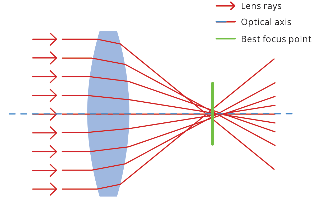
Figure 2.2.3: An Optical System With Spherical Aberration (OPTO Engineering, n.d.).
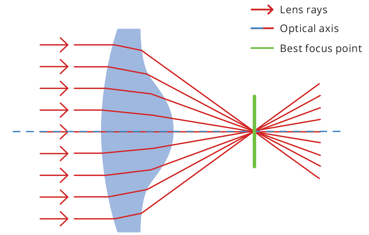
Figure 2.2.4: A Perfect Optical System With No Spherical Aberration (OPTO Engineering, n.d.).
In the figures above, we can see how spherical aberration occurs. The rays of light are not focused evenly and therefore result in aberration. This creates an area of uncertainty where an ideal focal point must be chosen, however due to the nature of such a system, there will be a margin of error that results in a blur. Notice how rays farther from the center of the lens stray from the focal point more. A way to combat this blur is by using irregular shaped lenses specifically catered to perfect lens redirection and minimize aberrations. In an SGL, the Sun's gravity and bending of light acts like a lens and cannot be altered, meaning the loss of focus cannot be directly countered (OPTO Engineering, n.d.). This focal blur can be quantified, and it surpasses the blur caused by diffraction. Regardless of how far an exoplanet is or how large a telescope's focal plane is, the blur produced by spherical aberration can be calculated by the geometry of an Einstein ring and will always have a blur with a characteristic width exactly half of the diameter of the exoplanet being imaged (Turyshev, 2018). If a planet had a diameter of 12,000km across, the blur in the image would be 6,000km wide. The solar corona also has effects on SGL image yield. When using a coronagraph, the majority of the Sun is blocked, except for its corona, the outermost part of its atmosphere. The corona is composed of plasma, which has an index of refraction (how much light slows down when passing through a material) extremely close to unity (unity means there is no refraction -- n = 1), however it is still more than one, meaning that refraction occurs (while small) and results in blur (Landis & NASA, 2018). The solar corona has large, prominent variations in density that are always changing. This means that light passing through different parts of the solar corona will experience different magnitudes of diminishing speed, and therefore, the blur caused by the solar corona is random and hard to combat. Furthermore, the gravity of other large objects (such as Jupiter) also has a small effect and disturbance on the path of incoming light, causing visible blur (Landis & NASA, 2018).
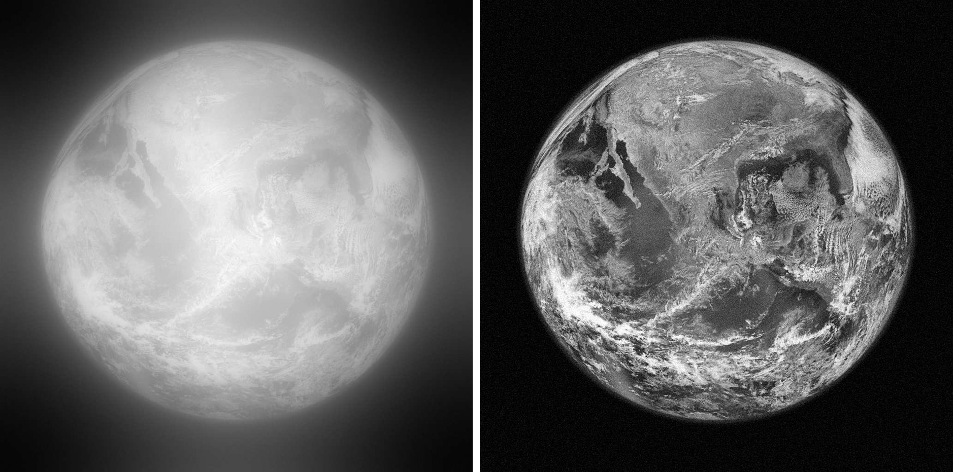
Figure 2.2.5: A Simulated Image Of Earth If Taken Through The SGL (Toth & Turyshev, 2021).
The above image depicts a simulation of an image of Earth created taken through the SGL. The simulation assumed the exoplanet was the distance of Proxima Centauri (~4ly) and that the focal point was at 650 AU. The left features the blurred, convoluted image, while the right depicts a reversed, deconvoluted image. It is important to note that the time to reverse the blur is significant, and can range up to a year (Toth & Turyshev, 2021). Despite these long integration times, once completed the results are stunning. From this, we can conclude that the major drawbacks that could limit the implementation of an SGL would be the focal blur caused by spherical aberration and the solar corona. However, it is possible to mitigate the effects of blur by reversing distortions in post-processing, and using shorter wavelengths (like infrared) which are affected less by refraction.
2.3.Exoplanet Selection And Imaging Methods
As previously mentioned, an SGL can image exoplanets with incredible resolution (1000x1000 pixels, 10km2 per pixel). However, this resolution has a limit of ~30 parcseconds (1 pc = 3.26 light-years) (Turyshev, 2018). This is roughly 98 light-years. Given the nature of an SGL mission, being single use, it is important to select an exoplanet for imaging before the mission is even launched. While an exoplanet for imaging is not explicitly stated in most studies, the requirements for a candidate are clear. A candidate for exoplanet imaging should be:
- Within close proximity (100 light-years or less) for optimal imaging resolution.
- Confirmed to exist on multiple accounts.
- Have possibility for habitability -- exoplanets with conditions suitable for life are preferred.
- Orbit a stable, bright star -- allows for optimal brightness when imaging.
While imaging any exoplanet would be an incredible feat, imaging an exoplanet that displays characteristics of habitability would provide the opportunity to confirm rising suspicions in exobiology and even revolutionize current understandings of extraterrestrial life. A potential candidate should be within the 100 light-year range to ensure optimal resolution, and should be confirmed to exist or have a high probability of existing to ensure that the target being imaged. Furthermore, the stability of the exoplanet's star is another factor to consider. It should be stable and bright enough to allow the SGL to collect enough photons in enough time without disturbances. It is preferred to image an exoplanet that orbits a G-type star (the same type of star as our Sun) that is not transiting (not passing in front of host star) (Turyshev, 2018). So, the exoplanet should be observed beforehand using Earth-based telescopes or space telescopes already in operation to confirm habitability. These observations would justify committing to a mission for imaging whi9le paving the way for an SGL mission to take place. Finally, pre-observations that confirm the exoplanet's inclination of orbit (angle of orbit in relation to us and its star, to know if it can/will transit), and orbital velocity would need to be taken. This data is required for an SGL-based telescope to accurately aim at the target exoplanet and successfully produce an image.
Imaging Methods:
An SGL significantly differs from traditional telescopes. Unlike regular telescopes, the image projected by the lens (in this case, the Sun's gravity) is larger than the imaging device itself. This poses interesting challenges, and opens the opportunity for solar sails to innovate and create solutions. The image plane is the region the focused light is projected and magnified onto. In an SGL mission, the image plane would be considerably large. This can be calculated using focal geometry. The below figure visualizes how the image is magnified onto the image plane.
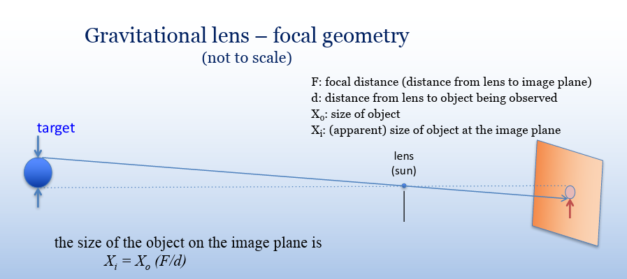
Figure 2.3.1: Calculating The Size of Objects On Image Planes (Landis, n.d.).
The Size Of The Object On The Image Plane, (Landis, n.d.):
Xi = Xo(F/d)
Where:
- Xi is equal to the apparent size of the object on the image plane.
- Xo is equal to the size of the object (diameter).
- F is equal to the focal distance--the distance from lens to the image plane.
- d is equal to the distance from the lens to the object being observed.
- *both F and d must be in the same units.
This equation describes the magnification ratio using focal geometry. It allows us to calculate the size of an object on the image plane by using the ratio of focal distance and distance from lens to object. Depending on the distance and size of the exoplanet, the size of the image on the image plane can vary. For example, an exoplanet at 100 lightyears would take up a 1km x 1km space on the image plane once magnified (Turyshev, 2018). However, the closer an exoplanet is, the larger its image on the plane is. Assume an exoplanet with Earth's diameter is imaged at 630AU, and is 10 LY away. Its apparent size would be reduced by a factor of 1000, meaning it would take up 12.5km x 12.5km on the image plane (Landis, n.d.), significantly larger than the exoplanet 100LY away. This means that when selecting an exoplanet, an additional factor should be considered with distance. The exoplanet should be close enough to ensure resolution, but far enough to allow for effective imaging methods to capture the light focused.
The large size of a magnified image on the image plane poses a significant challenge: collecting the light. If an image is spread out over kilometers, then it will be difficult to efficiently collect all of the light from the exoplanet over such a large area. Constructing an imaging device kilometers is impractical, and surpasses our current technological abilities. There are multiple solutions to this issue. Instead of using a large single telescope that encompasses the entire image plane, it is more feasible to send an array of smaller spacecraft, each capturing a single pixel on the image plane (Landis, n.d.). Solar sails are the obvious candidate for such a solution; they are cheap, long term methods of propulsion that can reach high velocities in short amounts of time. Furthermore, an array would allow for smaller individual imaging devices, meaning a lighter payload and therefore more effective solar sails. An alternative solution may involve a single imaging device performing a raster scan by moving across the imaging plane on its own. However, this technique would require a smaller projection (~1km), as larger imaging projections would make the scanning time too long and implausible (Turyshev, 2018). Therefore, this imaging method may prove to be more effective if the target exoplanet is farther away.
Research
N/A
Data
N/A
Conclusion
3.Analysis & Discussion
The benefits of solar sails and SGLs are astounding. They provide an innovative approach to many of the issues we face in space science today. It is nessesary to understand some of the challenges that this innovative approach faces, however. Solar sails provide a groundbreaking approach to deep space travel but can be hindered. The lack of research and practical use of solar sails implies that they still need refining before being used. Solar sail designs like the heliogyro and spinning disk must be proven effective before being considered for a long-term mission. Furthermore, there is a risk of degradation in the sail caused by microscopic particles and micrometeoroids impacting the sail's membrane. Fortunately, this is a rare event (micrometeoroids are spread out and not common), and will most likely have negligible impact on the effectiveness of a solar sail because of the size and effectiveness of the membrane. Solar sails have proven themselves to be an innovative approach to transportation that can surpass the limits of traditional propulsion methods and, as a result, are a strong candidate for a mission to the SGL. The use of an SGL provides countless opportunities and likewise, many challenges. The blur caused by the solar corona and spherical aberration from light warping is a significant issue that must be addressed to effectively use SGLs going forward. Einstein rings produced by SGLs must be reversed in order to observe any data collected, which is another inherent issue with the system that takes incredible amounts of time to resolve. Models to counteract this distortion should be refined before a mission is considered.
The implications found by using such a system, however, are magnificent. Solar sails could revolutionize not only deep space travel, but interstellar travel, paving the way for future missions outside of our solar system. Solar sails have various implications. They could be used as a cheap, fuel-free method to transport payloads between celestial bodies, or survey nearby planets. If invested in, solar sails have the ability to provide a new method of transport that transcends current capabilities. The use of SGLs would be profound; they would provide us with the first ever direct, detailed images of an exoplanet; another world never seen before, pushing the boundaries of our current telescopes. A successful solar sail mission to the SGL could revolutionize our understanding of exoplanets and potentially uncover signs of extraterrestrial life, raising important ethical and philosophical questions about humanity's role in the universe.
3.1.Conclusion
The use of solar sails in an SGL mission represents a revolutionary milestone in both space travel and imaging. This project has demonstrated that solar sails are a transformative technology for exploring the intricacies of space, offering an innovative approach to deep-space travel and pushing the boundaries of current technological limits in telescopy. The use of these technologies has been proven to be viable and attainable, and while the feasibility of this concept has been proven, there are still critical areas to explore to refine this groundbreaking idea into a tangible system. Further research into advanced materials, such as nanomaterials or metamaterials, is essential to optimize solar sail reflectivity, durability, and lightweight properties. Additionally, exploring the reversal of distortions (specifically Einstein rings) in much more depth is needed develop computational models that can simulate image reconstruction and distortion reversal. Refining these algorithms is crucial for overcoming this challenge and improving the accuracy of exoplanet imaging, while minimzing computational time. These issues are yet to be addressed, but once understood, we can refine this innovative idea into a tangible system with limitless potential. It is no doubt that overall, the use of solar sails and SGLs is an incredible groundbreaking method to tackle the problems that current day telescopes face. Such a system, once created, would irreversibly alter the way humanity perceives the universe.
The hybrid solar sail design, combining square and heliogyro sails, has shown promise in balancing velocity/acceleration and maneuverability, but further optimization through simulations or small-scale experiments is needed to ensure its practicality. Further environmental testing under simulated extreme space conditions would need to be conducted (such as solar radiation or micrometeoroid impacts) to evaluate the durability of solar sail membranes. Moreover, intricate mission planning and path/trajectory analysis must be conducted to maximize gravitational assists and create the most efficient path to the Solar Gravitational Lens. Beyond the technical challenges, SGLs have been proven to magnify with resolutions never seen before, superseding the largest and strongest telescopes we have to date. From their theoretical origins to practical applications, solar sails have demonstrated their potential to revolutionize deep-space missions, including those to the Solar Gravitational Lens. By harnessing the power of sunlight, solar sails could enable humanity to explore the farthest reaches of our solar system and unlock new frontiers in astronomy and science.
Citations
References
Coulter, D. (2008, August 1). A Brief History of Solar Sails. PHYS.ORG. https://phys.org/news/2008-08-history-solar.html
Dornshuld, E. V. (n.d.). Chemistry I. 3.2 Electromagnetic radiation. https://general.chemistry.msstate.edu/books/chem1/electromagnetic-radiation.html
ESO & Bohn et al. (2020, July 22). First ever image of a multi-planet system around a Sun-like star. ESO. https://www.eso.org/public/images/eso2011b/
ETH Zurich. (n.d.). SPHERE - Spectro-Polarimetric High-contrast Exoplanet Research. https://quanz-group.ethz.ch/research/observations/vlt-sphere.html#:~:text=ESO%27s%20%22Planet%20Finder%22%20and%202nd%2Dgen%20VLT%20instrument&text=The%20instrument%20achieves%20an%20angular,imagers%20for%20high%20contrast%20observations
Fisher, A., & NASA. (2022, September 1). NASA’s Webb Takes Its First-Ever Direct Image of Distant World. https://blogs.nasa.gov/webb/2022/09/01/nasas-webb-takes-its-first-ever-direct-image-of-distant-world/
Landis, G. A. (n.d.). A Telescope at the Solar Gravitational Lens: Problems and Solutions. https://ntrs.nasa.gov/api/citations/20180003479/downloads/20180003479.pdf
Landis, G. A., & NASA. (2018, October). A TELESCOPE AT THE SOLAR GRAVITATIONAL LENS: Problems and Solutions. Journal of the British Interplanetary Society, 71(10), 369-374. https://bis-space.com/membership/jbis/2018/JBIS-v71-no10-October-2018-5fpe41.pdf
Miller, R. (2015). Exploring Solar Sails. Physics. http://ffden-2.phys.uaf.edu/webproj/212_spring_2015/Robert_Miller/physics.html
NASA. (2022, September 30). Gravitational Lensing. https://hubblesite.org/contents/articles/gravitational-lensing
NASA, Caldwell, S., & Bowman, A. (2024, October 11). What is the Advanced Composite Solar Sail System? Advanced Composite Solar Sail System: Using Sunlight to Power Deep Space Exploration (ACS3) - NASA. https://www.nasa.gov/smallspacecraft/what-is-acs3/
NASA, ESA, & L. Calçada. (2011, April 12). Gravitational lensing in action. https://esahubble.org/images/heic1106c/
NASA & Johnson, C. L. (n.d.). Solar Sail Propulsion. nasa.gov. https://ntrs.nasa.gov/api/citations/20120015076/downloads/20120015076.pdf
National Aeronautics and Space Administration, Science Mission Directorate. (2010). Anatomy of an Electromagnetic Wave. http://science.nasa.gov/ems/02_anatomy. (n.d.).
National Aeronautics and Space Administration, Science Mission Directorate. (2010). Infrared Waves. http://science.nasa.gov/ems/07_infraredwaves. (n.d.).
OPTO Engineering. (n.d.). Aberrations In Optical Systems. https://www.opto-e.com/en/basics/aberrations
SolarSailWiki. (n.d.). Solar Sails Info. http://wiki.solarsails.info/index.php/Category:Design
Toth, V. T., & Turyshev, S. G. (2021, June 14). Image recovery with the solar gravitational lens. https://link.aps.org/accepted/10.1103/PhysRevD.103.124038
Turyshev, S. G. (2018, October). DIRECT MULTIPIXEL IMAGING OF AN EXO-EARTH with a Solar Gravitational Lens Telescope. Journal of the British Interplanetary Society, 71(10), 361-368. https://bis-space.com/membership/jbis/2018/JBIS-v71-no10-October-2018-5fpe41.pdf
UCLA Samueli Newsroom. (2021, July 15). Reinventing Solar Sail Technology to Push Space Exploration Boundaries. https://samueli.ucla.edu/reinventing-solar-sail-technology-to-push-space-exploration-boundaries/
ELPROCUS. (n.d.). What is a Solar Sail : Types & Its Applications. https://www.elprocus.com/solar-sail/
Acknowledgement
This project was a massive undertaking I had not even considered doing until this year. I want to thank all of the people who supported me throughout this process and pushed me to complete this project. Specifically by name, I'd like to thank my science fair coordinator, J. Sung who encouraged me to persevere through the project and enabled me to do my best. Her feedback and continuous dedication to me and my peers' projects is something I highly respect and am grateful for. Additionally, I would like to thank my close friend Suad, who encouraged me to do a project of my own. She informed me of CYSF and after showing me her project, inspired me to work on one as well. My science teachers, specifically C. Hornick and C. Baptist were incredibly helpful throughout and provided me with the support I needed to understand many of the complex physics and equations that occurred in my project. Finally, I would like to thank my parents, who provided me with their unwavering support and encouragement despite my lows. They helped me throughout my project, whether it was gathering necessary materials or providing feedback. I couldn't have asked for better parents.
I am forever grateful for all of the individuals who made this goal of mine possible. They are the reason this project exists. Thank you!
- Abdallah B