Generating Electricity from Snow Using a Snow-Based Triboelectric Nanogenerator
Ashley Chan, Husna Harimurugadass
North Trail High School
Grade 10
Presentation
No video provided
Problem
Energy Poverty
About 30% of households in Atlantic Canada, composed of more than 300 communities, with one-third of them being indigenous people, are facing energy poverty. Energy poverty is a global issue that still persists despite initiatives of energy poverty eradications, with 760 million people people living without electricity worldwide, and 2.3 billion rely on traditional fuels for cooking that causes approximately 3.7 million premature deaths annually. Energy poverty rates are high mainly in rural areas increasing worries about adequate treatment accessibility for health issues caused by burning solid fuels. Burning solid fuels in small huts and houses fills them with smoke due to their compact house sizes causing them to suffocate and prone to fatal health disorders including pneumonia, stroke, heart disease, chronic obstructive pulmonary disease, and lung cancer. Solid fuels responsible for these causes include wood, crop residues, dung, charcoal, and coal. The solution, pretty obvious, is to switch from using solid fuels to using renewable energy. However, the factor that plays an enormous role in this making this shift harder is affordability as energy poverty is faced in rural isolated areas making them challenging to commute to especially due to drastic climate changes that made icy roads impossible to cross (burning of fossil fuels also contribute to this as the soot that lands on the ice tends to form a black covering that warms and melts the ice beneath). Factors that affect and indicate energy poverty in a household includes, but is not limited to, (a)The inability to maintain sufficient heating systems at home, (b)The rate of people with arrears in paying their utility bills, (c)The share if households with a leaking roofs, damp walls, floors, foundations, and rot in window frames or floors, (d)The population that is at risk of poverty with income below 60% of the county's average. These factors help us narrow down our problem in order to solve it with the three main factors that affects energy poverty being affordability, geographical location(commutability and expenses related to commuting), and the need for renewable energy for the future of the people and our planet.
The innovative, promising, and a major solution can possibly be a snow-based triboelectric nanogenerators. The snow-TENG has the capabilities to solve the problem of energy poverty, more specifically, it tends to solve all the factors that are the root causes of energy poverty. The snow-TENG is affordable as it has a wide range of materials that can be used to curate and customize it according to the user's needs and affordability. It can also be used in rural Atlantic areas as snow is a crucial part of its ability to function, making it renewable as the snow that is melt after usage can either be discarded or filtered for drinking water; either way does not affect the planet negatively. Further experiments and investigations on the snow-TENG throughout this report will determine whether it is a suitable solution for households living in rural, and snowy regions of the world.
Method
What is a Snow-TENG?
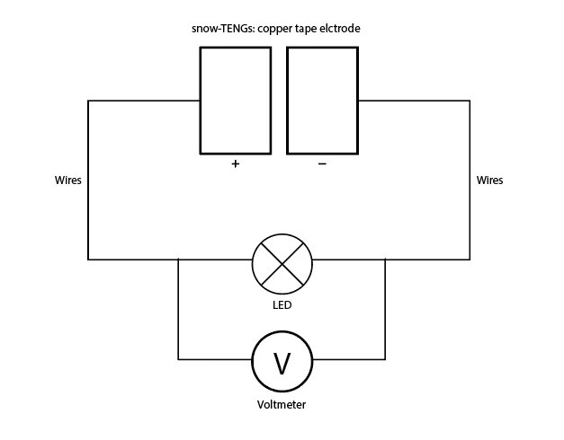
A snow-triboelectric nanogenerator (snow-TENG) is a device that generates electricity from the charge carried by snow, essentially through static electricity, also known as the triboelectric effect, and the natural properties of snow. A snow-TENG is comprised of two layers: a triboelectrification layer, or the component that captures charge through contact, and the electrode layer responsible for conducting the charge for electricity.
Typically, TENGs can operate in four different modes:
- lateral sliding mode
- contact-separation mode
- single electrode mode
- free-standing triboelectric layer mode
A snow-TENG will operating in single electrode mode, which is where only one electrode and triboelectric layer is paired. This allows for more freedom in design and simplicity, and can be freely moving. A major part in the principles of a snow-TENG, is the fact that one of the requirements of resources was snow, which is naturally occurring, reducing material demand and enforcing cost-effectiveness. The snow that would be used comes from cleared paths and roadways, which would otherwise be piled up on the side. Since snow cover extends over 46,000,000 square kilometers, or about 31% of Earth’s land area each year, we can exploit this to generate electricity, especially in cold regions afflicted by energy poverty.
Material Selection
In order to select the most optimal material for each component of the snow-triboelectric nanogenerator, we must identify the application goals and requirements, such as the level of flexibility, durability, and more, to find a balance that works without compromising its power generation ability. We also have to account for external influences and factors that may pose a challenge in energy generation, of which include the types of snow, the formation of ice, heavy snow accumulation, and extreme temperatures, as well as evaluating the material's cost, lifespan, availability, sustainability, and other impacts. We also have to consider our capabilities in resources, fabrication limits, and technical expertise. These are all important factors that stem into the snow-TENG's energy generation performance and constraints. Material selection in relation to energy harvesting, is also one of the most fundamental influences in the initial and final performance, and is crucial for the output capacity.
TENGs are very versatile and cost-efficient regarding the materials which, means that many options are open and have potential in application, as well as modifying the design in its materials.
The Goal / Idea / Application
Snow is made up of many tiny ice grains surrounded by air, and as the grains are compressed, they rub against each other and create friction and resistance. It is observed that the lower the temperature, an increase of friction between the grains of ice is seen. A greater contact surface and friction could increase the generation of electricity through snow-TENGs, done by creating an environment for which to occur. This could be done by attaching the snow-TENG to a shovel or snow removal machines and the like. A machine similar to the idea a grain bin could be exploited to generate electricity as the rotational force inside can create a surpass of friction to generate charge. Mass amounts of snow removed from sidewalks and roadways to be placed inside to undergo friction, and as snow is cleared, it will reduce the loss of life through road accidents, falls on ice, and more due to hazardous conditions associated with cold, snowy, weather. Anytime there is friction, heat is generated, causing the snow to melt, we can use this to melt snow for water as well to be used as drinking water after filtration, or for use in other purposes, such as another use in generating electricity as a steam-powered generator. A schematic of the design will be presented along with our trifold and prototype in person.
Components & Their Properties
1. A triboelectrification layer
The triboelectrification layer works to generate surface charge through contact triboelectrification, which is the process where in the contact of two originally uncharged materials initiate a charge transfer due to physical contact and by their respective electron affinities. Mechanical friction can aid the transfer of electrons, but is unnecessary for the process. The triboelectrification layer is typically a dielectric material, that is an insulating material able to transmit and store charge, measured by its dielectric constant. The higher the dielectric constant is means a better surface charge density and corresponds to performance. Snow should have a weaker electron affinity than the triboelectrification layer, because in contact with a strong tribo-negative material which has a high electron affinity and a tendency to gain electrons, the snow's charge will be attracted and acquired as surface charge. The larger the difference in electron affinities directly influence the performance of a snow-TENG.
This phenomenon can be described using the electron-cloud-potential-well model. In short, each material has its own electron cloud and in its overlap, there is a change of energies and electric fields and a difference in electro-cloud potentials, which based on each materials electron affinities, cause some electrons to break free onto the material with a stronger electron affinity.
The material used in our prototype for the triboelectrification layer was selected based on durability and generation ability, which would greatly differ, for example if the focus was wearability. One of the options was silicone because of its properties as a strong tribo-negative material that easily attracts and hold onto electrons because of its high surface charge. While silicone is a good option, its flexibility means that it lacks durability and structural rigidity and becomes brittle in freezing conditions or gets degraded over time. Other options were graphene for its environmental benefits, Kapton, PVC, and others along those lines.
Although there were many possibilities of materials the triboelectrification layer could be, the final selection was PTFE, also known as polytetrafluoroethylene, a dielectric polymer. PTFE is the most optimal for the goal of our snow-TENG and its application. One of the most influential reasons was that PTFE ranked highest as a tribo-negative polarity material as the strongest electron acceptor, and consistently ranked high in multiple areas such as surface charge density, friction coefficient, strength of polarization, the utilization rate of triboelectric charges, and stability as basic parameters as shown in Figure 1 and 2, respectively. PTFE was also a material that was relatively inexpensive and easy to acquire.
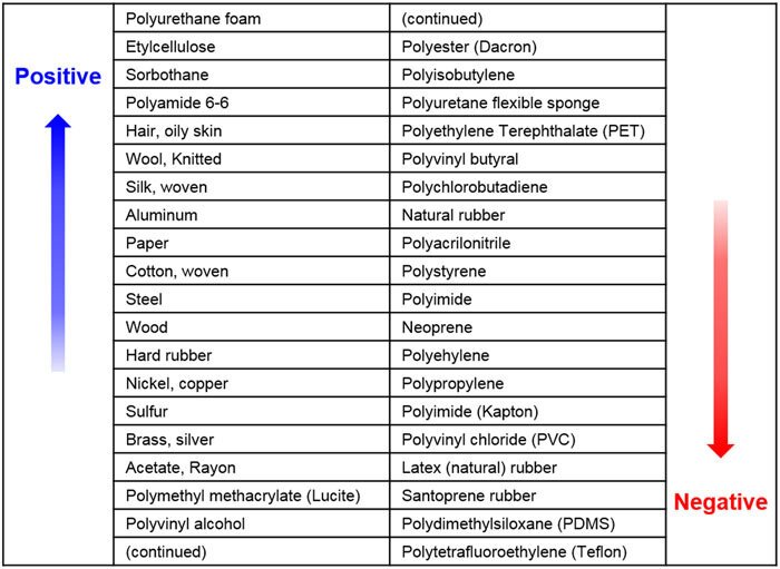 Figure 1 - Ranking of various materials according to tribo-negativity and their tendency to gain or lose electrons\, called as the triboelectric series. Source: https://www.researchgate.net/figure/A-list-that-ranks-various-materials-according-to-their-tendency-to-gain-or-lose-electrons_fig3_315903559
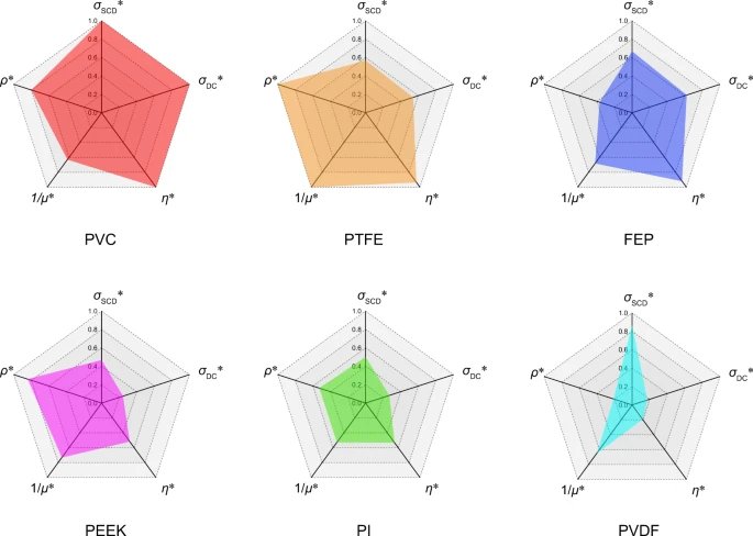 Figure 2 - The radar chart of normalized indexes of PVC\, FEP\, PTFE\, PEEK\, PI\, and PVDF\, where the σSCD*\, σDC*\, η*\, 1/μ*\, and ρ* is the normalization of σSCD: surface charge density\, σDC: DC charge density\, η: (σDC/20)/σSCD\, 1/μ: the reciprocal of friction coefficient\, ρ: stability\, respectively. Source: https://www.nature.com/articles/s41467-021-25046-z#:\~:text=At%20the%20same%20time%2C%20they\,%2C%20%CF%81:%20stability%2C%20respectively.
Much of PTFE's properties are due to its fundamental molecular structure, comprised of strong, stable, tightly bonded carbon-fluorine (C-F) bonds as illustrated in Figure 3. Fluorine is a highly electronegative element which means that it has a tendency to hold on to electrons very tightly, and when bonded with another element, it results in a short, high energy bond. PTFE is a long chain of carbon atoms surrounded by a sheath of fluorine atoms in polar covalent bonds. Forming a dense structure with high intermolecular forces means that its surface is smooth with a nearly impenetrable surface to other substances. This translates into low friction for less wear and tear over time and hydrophobic properties also due to it polarity. Due to the strong electrostatic attraction, a significant amount of energy is required to break the bond, which means it is extremely resistive to corrosion, rust, degrading, reacting, melting, and becoming brittle. This bond also contributes to environmental benefits because of longevity in performance to reduce consumption and since it is chemically inert, it will not leach chemicals or contaminate the environment through such means as reacting in contact with another substance. The relationship between carbon and fluorine atoms ultimately makes PTFE an incredibly durable material suitable for our prototype, along with other properties outlined in Table 1.
 Figure 3 - Chemical structure of PTFE. Source: https://enkidupolymers.com/what-is-ptfe/
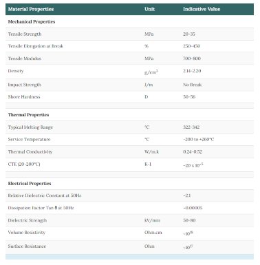 Table 1 - Indicative property values of PTFE. Source: https://enkidupolymers.com/what-is-ptfe/
The selection of PTFE was not based on one factor but multiple regarding electron affinity, chemical composition, and physical features (elasticity, friction, and surface topographical structure) to ensure no area is lacking. Even so, any materials performance ability can still be improved.
2. Electrode
The electrode works to collect the charges from the triboelectrification layer and pass it on. As for the electrode, properties such high conductivity, surface charge density, resistance, stable power output, retention of conductive pathways, durability, resistance to deformation, were considered in its selection. Two options were narrowed down, which were conductive polymers or metal electrode. Conductive polymers were found to have more use in transparency or flexibility in applications of wearable TENGs or as covers for solar panels, however they did not compare to the output and conductivity of that of a metal electrode. There were many options of metals as the best electrode. Silver, copper, and were top contenders, but in the end copper prevailed because of its availability, relative affordability, and overall performance. Copper is an efficient electrode due to its high conductivity, ranking only second to silver, which compensated in price, listed in Table 2 on resistivity and conductivity level comparisons. The corrosion resistance of copper is exceptional, and works because of surface oxidization, or patina, which protects from the deterioration of the metal and preventing corrosion from penetrating the surface. This results in an excellent resistance to corrosion, which only affects the appearance and not the matrix or copper, and to surrounding environments, showing for corrosion rates less than 0.4mm over 200 years. As well as acting as a corrosion resistant barrier, patina extends the lifespan of copper, reducing the need for replacements which is beneficial for the design and the environment, and material usage efficiency. Copper is also versatile in its applications because it holds up to rust, weathering, and soil corrosion, and can be recycled. It has been found that an estimation out of the mined 12% of the world supply, 60% is still used today.
Table 2 - Table of Resistivity and Conductivity at 20°C
| Material | ρ (Ω•m) at 20 °C Resistivity | σ (S/m) at 20 °C Conductivity |
|---|---|---|
| Silver | 1.59×10⁻⁸ | 6.30×10⁷ |
| Copper | 1.68×10⁻⁸ | 5.96×10⁷ |
| Annealed copper | 1.72×10⁻⁸ | 5.80×10⁷ |
| Gold | 2.44×10⁻⁸ | 4.10×10⁷ |
| Aluminum | 2.82×10⁻⁸ | 3.5×10⁷ |
| Calcium | 3.36×10⁻⁸ | 2.98×10⁷ |
| Tungsten | 5.60×10⁻⁸ | 1.79×10⁷ |
| Zinc | 5.90×10⁻⁸ | 1.69×10⁷ |
| Nickel | 6.99×10⁻⁸ | 1.43×10⁷ |
| Lithium | 9.28×10⁻⁸ | 1.08×10⁷ |
| Iron | 1.0×10⁻⁷ | 1.00×10⁷ |
| Platinum | 1.06×10⁻⁷ | 9.43×10⁶ |
| Tin | 1.09×10⁻⁷ | 9.17×10⁶ |
| Carbon steel | (1010) | 1.43×10⁻⁷ |
| Lead | 2.2×10⁻⁷ | 4.55×10⁶ |
| Titanium | 4.20×10⁻⁷ | 2.38×10⁶ |
| Grain-oriented electrical steel | 4.60×10⁻⁷ | 2.17×10⁶ |
| Manganin | 4.82×10⁻⁷ | 2.07×10⁶ |
| Constantan | 4.9×10⁻⁷ | 2.04×10⁶ |
| Stainless steel | 6.9×10⁻⁷ | 1.45×10⁶ |
| Mercury | 9.8×10⁻⁷ | 1.02×10⁶ |
| Nichrome | 1.10×10⁻⁶ | 9.09×10⁵ |
| GaAs | 5×10⁻⁷ to 10×10−3 | 5×10⁻⁸ to 103 |
| Carbon (amorphous) | 5×10⁻⁴ to 8×10⁻⁴ | 1.25 to 2×10³ |
| Carbon (graphite) | 2.5×10⁻⁶ to 5.0×10⁻⁶ //basal plane 3.0×10⁻³ ⊥basal plane | 2 to 3×10⁵ //basal plane 3.3×10² ⊥basal plane |
| Carbon (diamond) | 1×10¹² | \~10−13 |
| Germanium | 4.6×10⁻¹ | 2.17 |
| Sea water | 2×10⁻¹ | 4.8 |
| Drinking water | 2×101 to 2×10³ | 5×10⁻⁴ to 5×10⁻² |
| Silicon | 6.40×10² | 1.56×10⁻³ |
| Wood (damp) | 1×10³ to 4 | 10−4 to 10-3 |
| Deionized water | 1.8×10⁵ | 5.5×10⁻⁶ |
| Glass | 10×1010 to 10×1014 | 10−11 to 10−15 |
| Hard rubber | 1×10¹³ | 10−14 |
| Wood (oven-dry) | 1×10¹⁴ to 16 | 10−16 to 10-14 |
| Sulfur | 1×10¹⁵ | 10−16 |
| Air | 1.3×10¹⁶ to 3.3×10¹⁶ | 3×10⁻¹⁵ to 8×10⁻¹⁵ |
| Paraffin wax | 1×10¹⁷ | 10−18 |
| Fused quartz | 7.5×10¹⁷ | 1.3×10⁻¹⁸ |
| PET | 10×1020 | 10−21 |
| Teflon | 10×1022 to 10×1024 | 10−25 to 10−23 |
Source: https://www.thoughtco.com/table-of-electrical-resistivity-conductivity-608499
3. Snow
Snow Electrification
In a further investigation on how snow-TENGs take effect, includes the mechanism of snow electrification explicable in terms of the temperature-gradient theory and contact electrification by asymmetric rubbing.
The temperature-gradient theory, or otherwise known as the Latham-Mason theory, is that ice particles become charged due to charge separation and transfer associated with temperature gradients in the snow surface at the time of disruption. This process happens because (i) the concentrations of H+ and OH- ions in ice rise rapidly with increasing temperature, and (ii) the mobility of the ice crystal's H+ ion is much higher than the OH- ions within the ice crystal. In the combination of a temperature gradient and an ionic concentration gradient, there will be an initial, rapid diffusion of H+ ions down the concentration/temperature gradient to colder regions, resulting in a net positive charge in the colder parts of the ice crystal, that is the extremities because of a higher evaporation rate than its interior. The temperature difference (∆T) across the ice crystal, leads to the colder end acquiring the positive charge and the equivalent negative charge remaining in the interior, for which a field of observed polarity will be produced. This is based on the ordering of electric dipoles of water molecules as they crystalize into snowflakes.
In addition to the temperature-gradient theory, electrification in snow occurs in the charge transfer accompanying temperature gradients established in ice, found on contact by asymmetric rubbing. Asymmetric rubbing is when in contact with another surface such as a snowflake, friction creates a temperature gradient responsible for charge separation, as it does not heat surfaces homogenously due to uneven surfaces. In the same manner, H+ ions head faster to the colder ends than the OH- ions, which obtain a negative charge, and form ionic defects, or irregularities in the crystal lattice of an ice structure, as depicted in Figure 5. As well as the occurrence of charge separation, a electric potential difference is generated and therefore an electric field when subjected to a temperature gradient, a phenomenon known as the thermoelectric effect.
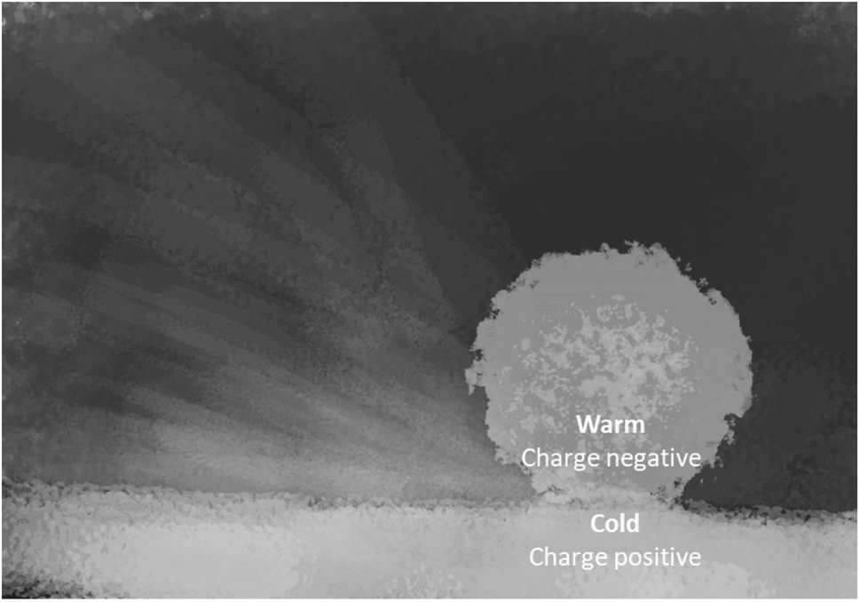 Figure 4 - Schematic representation of the effect of ‘asymmetric rubbing’ leading to electric charging of snow grains. Intensive friction creates higher temperature gradients and increases charge carrier concentration gradients because protons migrate faster toward cold regions. https://pubs.rsc.org/en/content/articlelanding/2024/ea/d3ea00084b
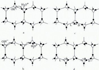 Figure 5 - The creation and movement of electrical point dejects in ice. In (a) the movement of u hydrogen nucleus from the position shown with a dashed circle creates a positive and a negative ion, and (b) shows how movements of the hydrogen nucleus along a bond can make the inns migrate, (c) shows how the movement of a hydrogen nucleus around an oxygen atom can create an L-defect and a D-defect, and (d) shows how this defect con also migrate by further movements around oxygen atoms. The movement of the hydrogen is to the right in all cases, but the movement of ions in (b) leaves water molecules oriented with their hydrogens to the left, while the movements of L- and D-defects in (d) leaves them with their hydrogens to the right.
Source: https://www.cambridge.org/core/journals/journal-of-glaciology/article/electrical-properties-of-snow-and-ice/6FE2CE36395E1F738FCB916FFD554E8A
Figure 5 - The creation and movement of electrical point dejects in ice. In (a) the movement of u hydrogen nucleus from the position shown with a dashed circle creates a positive and a negative ion, and (b) shows how movements of the hydrogen nucleus along a bond can make the inns migrate, (c) shows how the movement of a hydrogen nucleus around an oxygen atom can create an L-defect and a D-defect, and (d) shows how this defect con also migrate by further movements around oxygen atoms. The movement of the hydrogen is to the right in all cases, but the movement of ions in (b) leaves water molecules oriented with their hydrogens to the left, while the movements of L- and D-defects in (d) leaves them with their hydrogens to the right.
Source: https://www.cambridge.org/core/journals/journal-of-glaciology/article/electrical-properties-of-snow-and-ice/6FE2CE36395E1F738FCB916FFD554E8A
The mechanism called the polarization charging effect separates charge during the impact of polarized particles in an electric field and is known for increasing the electric field, further amplifying charge separation, which makes snow a dielectric material.
On collision with other snowflakes, objects, or an exposure to wind, surface drift, or frictional drag, the positive extremities break off leaving a negative center, occurring by crystal fragmentation. These ice splinters are carried upwards through ascending air currents and gravitational separation, for which a compensating positive charge is left on the tiny ice fragments or on the air as ions explained by point discharge. This is known because of an increase in the normal positive gradient, which indicates air gained a positive charge. At a lower level, the heavier snowflakes and partly on the earth's surface, contained the negative charge. Between the positively charged air and ground results in the creation of an electric field. Proportionally, the more wind at a higher velocity, means a higher positive potential gradient, or otherwise crystal fragmentation.
The results in a study on the electrical nature of snow particles, done by Ukitirô Nakaya and Tôiti Terada from Hokkaido University, reveals that negative snow particles generally proportionally surpass that of the positive in their findings, representing 63% of the total 1474 particles observed, as showing in the table below. This suggests that snow has a low electron affinity, meaning that it is a material with the tendency to give up electrons. The larger snowflakes are determined to be more often negatively charged, which contributes to the fact that positive charge is found at a higher elevation than smaller, or positively charged snowflakes.
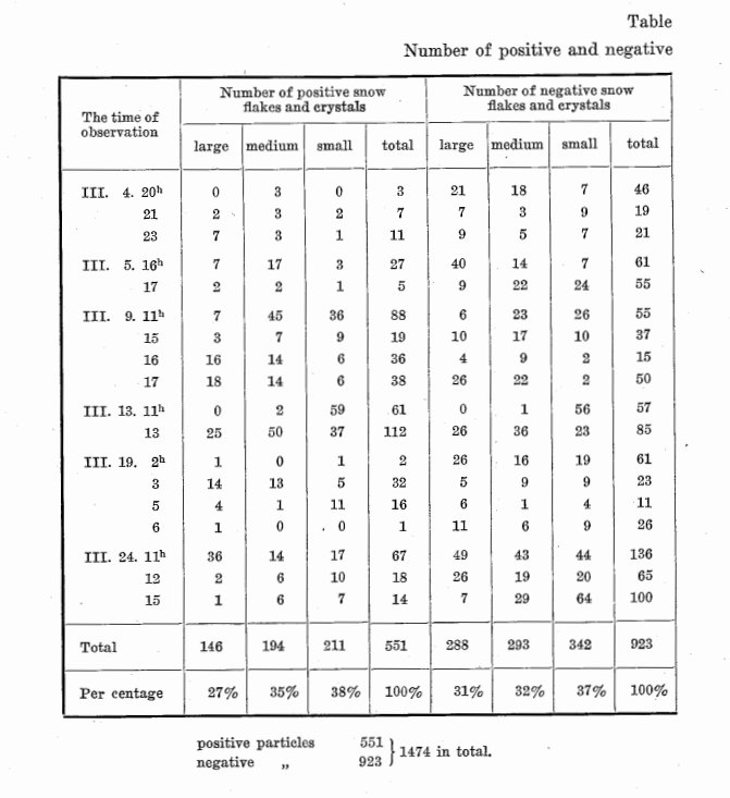 Table 3 - Summary of observation results of the sign of charge and snow particle size. Source: https://eprints.lib.hokudai.ac.jp/repo/huscap/all/34450/1_P181-190.pdf
In consideration of a snow-TENG, a larger portion of snowflakes being negatively charged is more advantageous for power generation and through its contact with the triboelectrification layer, it will loose its electrons.
Performance Improvements:
There are a few methods for performance improvement in a snow-TENG, including doping, fillers, surface modification, nano-fillers, micro-capacitors, and composites to enhance aspects such as capacitance, surface charge density, and more.
Doping is the process of deliberately introducing small impurities, called dopants, into a material to alter or enhance its properties, especially in material charge density as to a snow-TENG. This can be done to either the dielectric material or the electrode of the TENG, or to both. For the dielectric material, to improve its triboelectrification properties, notably its dielectric constant or its ability to store electrical energy, and electron affinity, can be done with the addition of a dopant with a high dielectric constant for charge transfer and retention. One study had achieved an enhancement of PTFE energy density by 65.7% and 85.7% with the use of Aluminum and fluorine doping. It had been found that fillers can be introduced to better its mechanical strength, and the same can be said for the electrode. The electrode's conductive properties can be enhanced and can be modified in physical manners, as dopants can interact with the crystalline-lattice structure and reduce charge resistance.
Increasing the contact area can help accumulate more charge as well as improving charge retention and reducing charge loss. This can be done in means such as surface modification through surface mirco- or nanostructuring to improve charge transfer efficiency. This increases the surface roughness, corresponding to the effective contact area and charge density. This can be done by the template method, laser ablation, and electrospinning among others. This has been found to provide PTFE with superhydrophobic properties from microscale grooves. Increasing porosity contributes to a similar effect as well in improving the contact electrification process.
The incorporation of nano-fillers and micro-capacitors into a material can aid in charge transfer, storage, and accumulation, as well as improved mechanical, thermal, and electrical properties at a molecular level. Fillers placed into a material can make up for what the host material is lacking and compatibility between materials and fillers can be further researched. It is important to reduce charge loss through the retention of conductive pathways in electrodes and ensuring stable power output and high surface charge density, so incorporating materials such as MXene or PDMS with a high charge-trapping efficiency in a material's composition can prevent the decay of generated charge. The maximum output of a TENG is also limited by air breakdown which is losing charge to the the ionization of air, although methods namely utilizing insulating coatings.
Another option is the creation of composites, which can combine properties of the materials to boost or cover lacking areas. The proportion of composites have a benefit of being flexible and present opportunities for customization to each application. Additionally, composites have the potential of providing versatile and affordable substitutes and options to the already wide range of selections. They can also offer many improvements, such as improved surface roughness, charge storage, and interfacial bonding, leading to increased voltage output, and stable energy harvesting. Employing alloys can also have a similar effect and could contribute to stability in metals and possibly stability in high humidity as it can affect the snow-TENG. Many forms can be tested. PTFE can come in many forms, such as expanded PTFE, a porous, high contact area and charge density option, mirco/nano particles used to create composite films, and electro-spun PTFE, which has a high surface area to volume ratio and surface charge density.
Providing that these methods are used, the output performance of a TENG, could be significantly maintained and amplified. These methods are only a few of the many possibilities of improving performance and there are numerous more, such as chemical modification through chemical reactions, ion implantation, incorporating nanocomposite layers, or changing the manufacturing process in areas like the cooling crystallization or synthesis of PTFE. This area of study in snow-TENGs and TENGs in general, hold much potential and could emerge in other areas of study, including aerospace engineering, medicine, or other scopes, and can employ hybridizing with other technologies in future advancements.
Effects of Thickness:
During the material selection process, the consideration of material thickness was deemed important for a snow-TENG. The optimal thickness has been found that the thinner the material is, the better the charge density, efficiency, and such, and the output voltage dropped with increasing thickness. A certain thickness is still necessary before capabilities deteriorate, which was consistently apparent in many studies, such of the one in Figure 6, going into the millimeter range, and in some into nanometers. The surface charge density is increased because there is more electric charge per unit area, and a thinner triboelectric layer closes in the distance between surface charges and the electrode, which means charge transfers more efficiently and translates into a more effective mechanical energy to electrical energy conversion, and in turn the snow-TENG's performance.
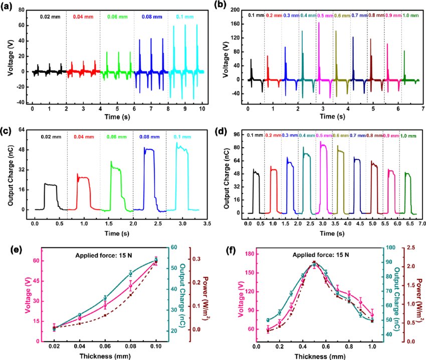 Figure 6 - The output voltage waveforms of several cycles at different PTFE thicknesses below 0.1 mm. (b) A comparison of output voltages of one cycle at different thicknesses of the PTFE film. (c) Output charges at different PTFE thicknesses below 0.1 mm. (d) A comparison of output charges of one cycle at different thicknesses of the PTFE film. (e) The dependence of voltage, output charge, and power with PTFE thickness below 0.1 mm. (f) The dependence of voltage, output charge, and power with PTFE thickness from 0.1 mm to 1 mm.
Source:https://www.researchgate.net/publication/326645636_Comprehensive_dependence_of_triboelectric_nanogenerator_on_dielectric_thickness_and_external_impact_for_high_electric_outputs
Figure 6 - The output voltage waveforms of several cycles at different PTFE thicknesses below 0.1 mm. (b) A comparison of output voltages of one cycle at different thicknesses of the PTFE film. (c) Output charges at different PTFE thicknesses below 0.1 mm. (d) A comparison of output charges of one cycle at different thicknesses of the PTFE film. (e) The dependence of voltage, output charge, and power with PTFE thickness below 0.1 mm. (f) The dependence of voltage, output charge, and power with PTFE thickness from 0.1 mm to 1 mm.
Source:https://www.researchgate.net/publication/326645636_Comprehensive_dependence_of_triboelectric_nanogenerator_on_dielectric_thickness_and_external_impact_for_high_electric_outputs
The proximity between the layers have some impact as well, where the closer or smaller the gap is, the better the TENG will fare. The complete contact of the surfaces is not possible because of microscopic surface roughness or asperities, and because the material is a solid, and therefore can't fill in the gaps. It should be aimed to maximize the triboelectric effect through ideally the most contact points.
In the selection of the triboelectrification layer, electrode, and tape, we tired to keep its thicknesses to a minimum, while still keeping to our budget and limits of availability, resources, and other specifications we were looking for.
Anti-icing:
As mentioned before in performance improvement options, though the use of doping, PTFE can obtain superhydrophobicity which can prevent water or ice from adhering to its surface and accumulating, known as ice accretion. Another anti-icing method in particular that benefits from this property is called electrostatic defrosting. It uses high voltage, low-current electricity, where a positive charge is over the ice, causing further polarization. The ice crystals will then detach because the electric force is strong enough to break them off and from the ionic defects. This method does not use heat, chemical, or mechanical force to de-ice a surface.
It is worth mentioning that it may be difficult to find an effective method for anti-icing without compromising the snow-TENGs performance because contact is one of the most crucial aspects for the process of generating electricity from snow, which makes this an area that would benefit with more deliberation.
Costs & Materials
PTFE (Polytetrafluoroethylene) -
Price: \~$14.99 ○ Amazon: link
- 100% pure PTFE
- 30cm x 100cm
- Thickness: 0.1mm
- temperature range from 350℉ to 500℉
Copper sheet roll -
Price: \~$15.48 ○ Amazon: link
- 99.9% pure copper
- Size: 2000mm x 60mm
- Thickness: 0.06mm
Copper foil tape -
Price: $8.59 ○ Amazon: link
- 0.5 cm x 20m
- single side conductive glue
LED Lights with wires-
Price: N/A (borrowed from a parent)
- 5-12V
Alligator Clip Wires x2 -
Price: N/A (borrowed from school)
- 70 cm long
Multimeter-
Price: N/A (borrowed from school)
Total Cost of Materials: \~$40
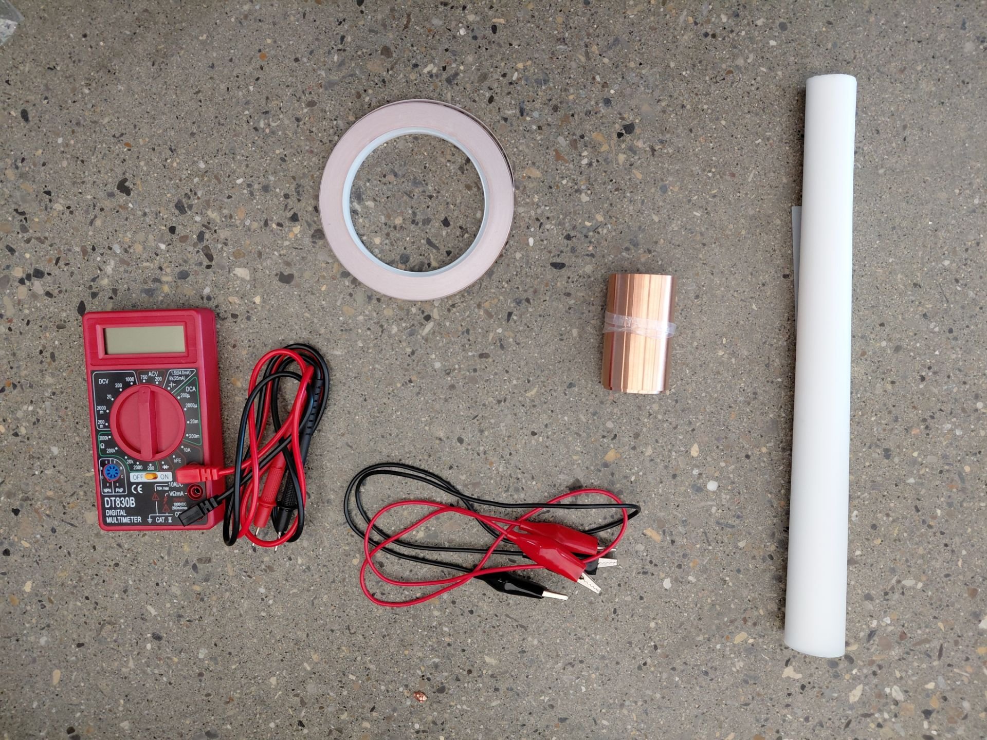
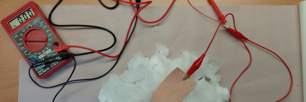
Figure 7 - Image of materials, including the multimeter, alligator wire clips, copper tape, copper sheet roll, and a PTFE sheet.
Snow-TENG Fabrication and Procedure:
Purpose: To make a snow-TENG that can generate electricity from surrounding snow to mitigate energy poverty in secluded regions and communities
Note: Our innovation project is still in a small scale and we hope to make improvements to construct a theory for scalability in the future for larger applications in energy generation through our research in this project.
Procedure
The multimeter was set to 200m on DCV, and the temperature was -12℃. In between each testing, or when the snow melted, the snow was replaced, and connection in the circuit was checked.
Prototype 1:
We began with cutting out our triboelectrification layer and electrode, or PTFE sheet and copper electrode, into 3cm by 6cm sized pieces and taped together the parallel long ends with copper adhesive tape, as presented in Figure 8 and 9.
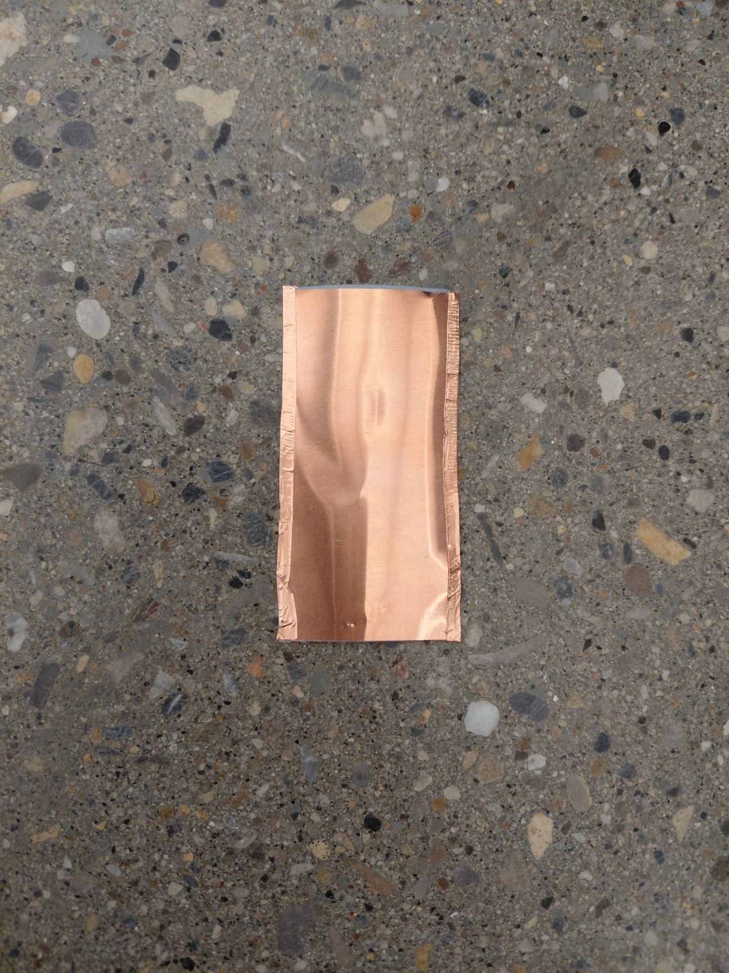 Figure 8 - Image of the copper electrode side of the snow-TENG. (Prototype 1)
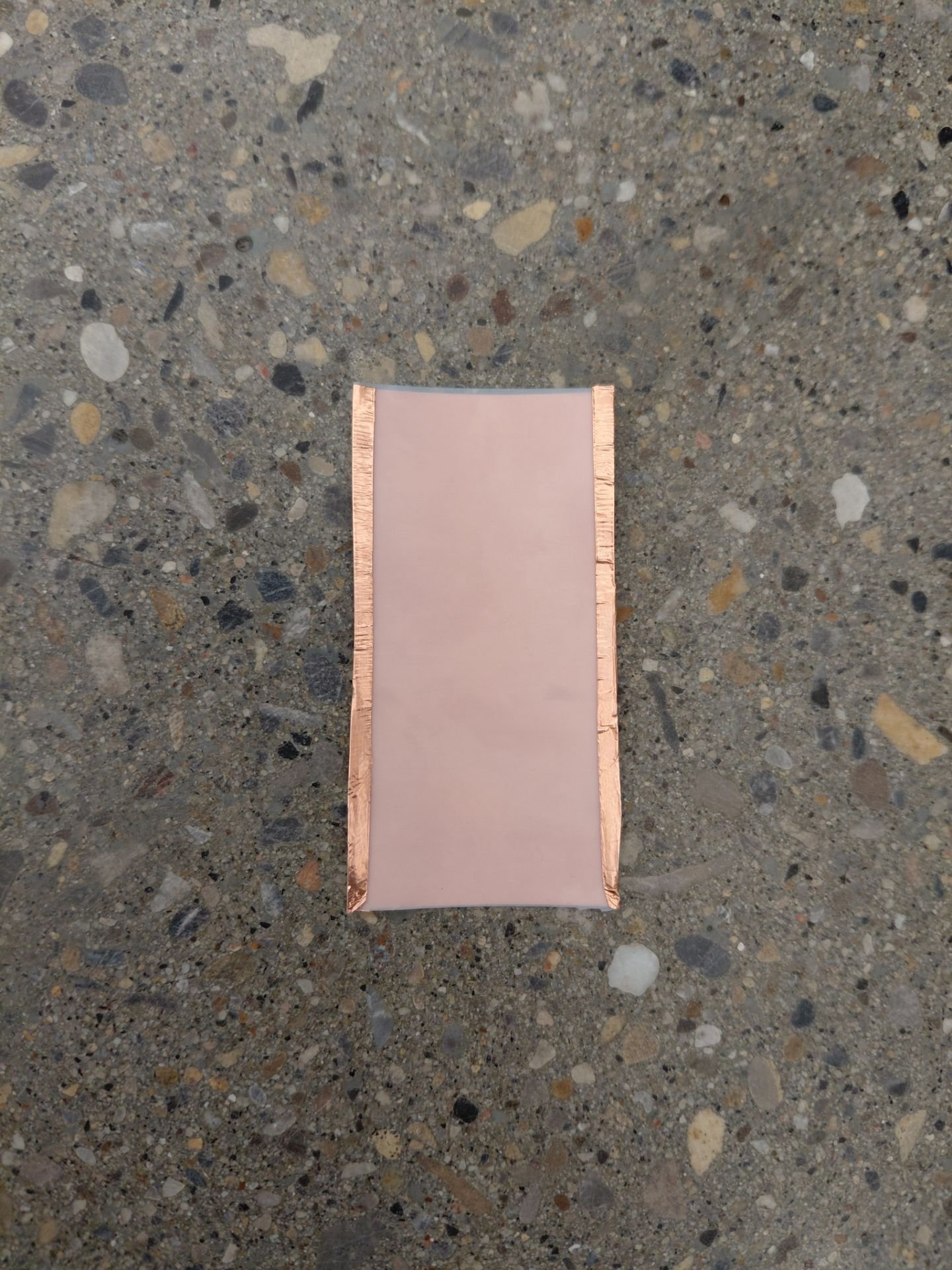 Figure 9 - Image of the triboelectric layer or PTFE side of the snow-TENG. (Prototype 1)
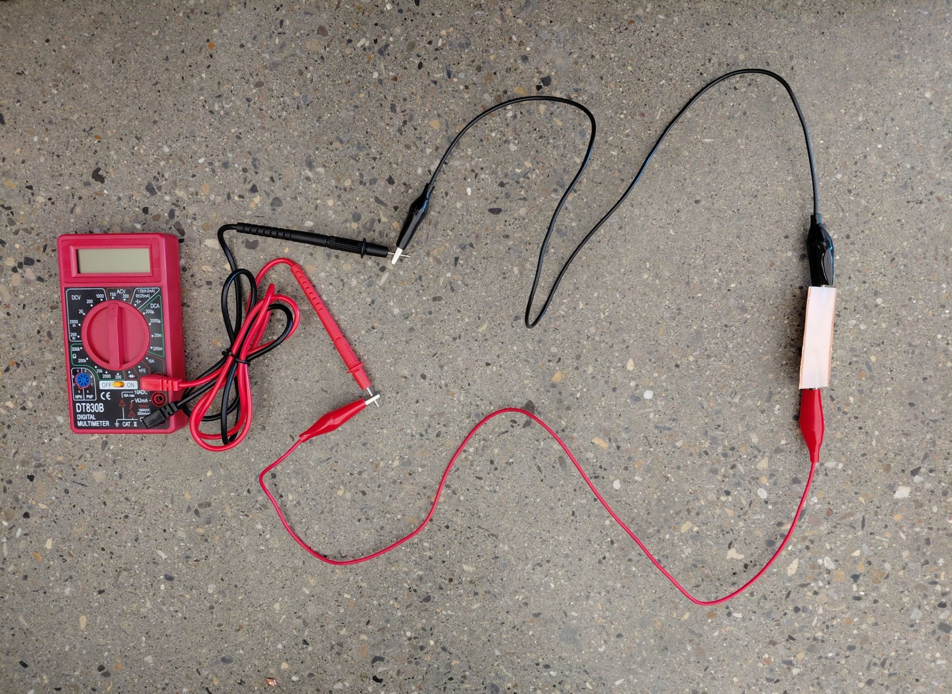
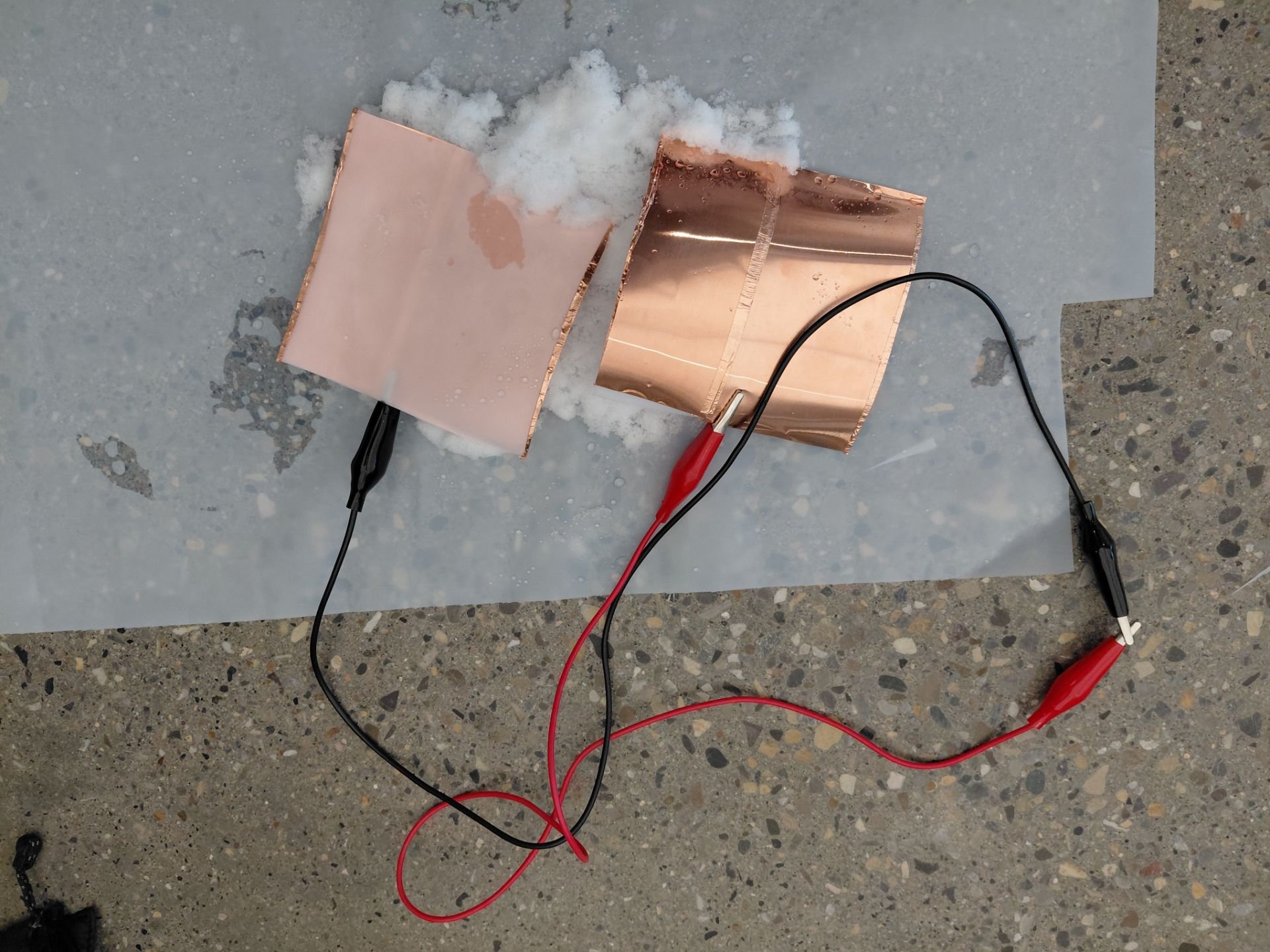
The alligator clip wires were attached to each of the short ends only on the copper electrode, with the other ends clipped onto the multimeter probes. This is shown in Figure 10.
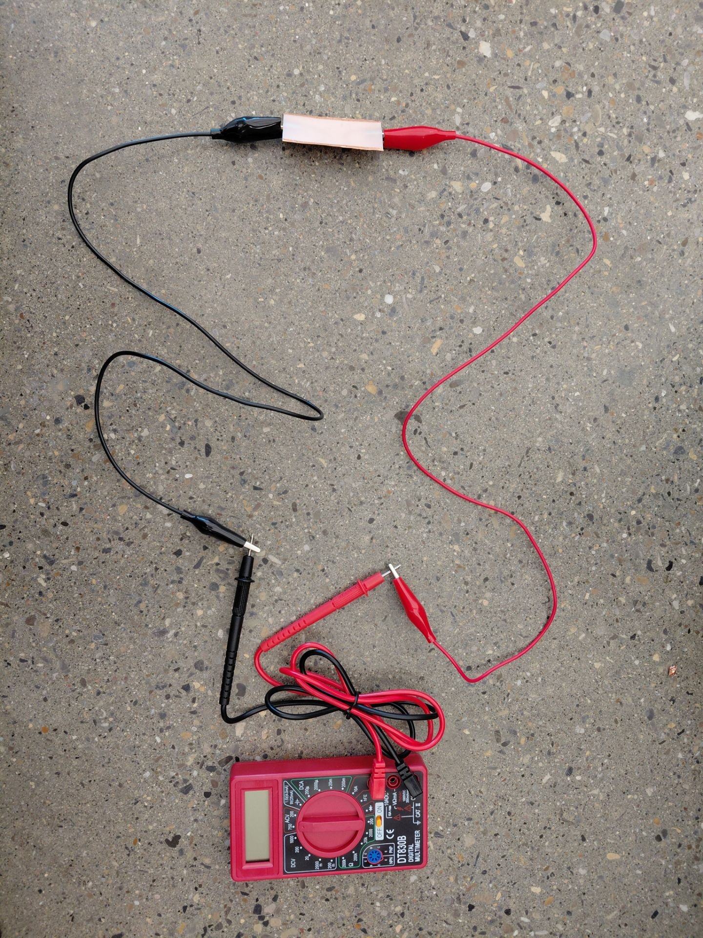 Figure 10 - Image of the entire circuit testing the snow-TENG\, including the multimeter\, alligator clip wires\, and set-up arrangement of Prototype 1.
Testing:
We began by checking the multimeter on a battery to test its operation. After it was satisfactory, we tapped and rubbed the snow-TENG on snow, however we saw only a slight fluctuation in voltage value, and attempted with the multimeter on different settings but saw no quantifiable result. We set it to 200m on DCV and the temperature was -12℃. In between each testing, or when the snow melted, the snow was replaced, and connection in the circuit was checked.
Attempt 2:
The multimeter was removed from the circuit and the ends were rejoined to be tested once more, with the probe tips touching the circuit components as a different means to get a reading. We still saw no apparent change.
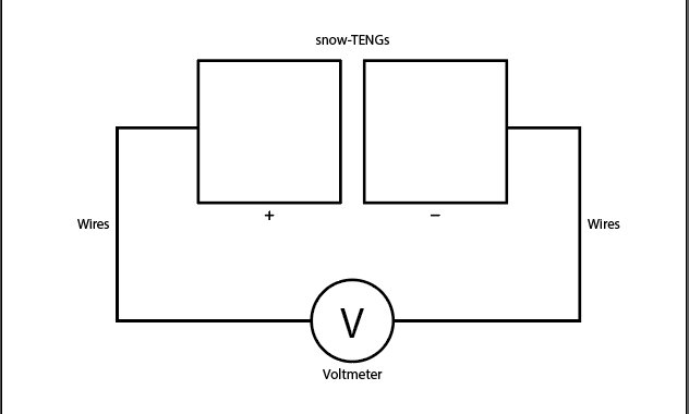
Prototype 2:
This time we cut out another 3cm by 6cm version of Prototype 1, where only one side of each alligator clip was clipped onto each snow-TENG, which the image in Figure 11 represents. This was done to test if two would make a difference as in other studies of energy generation using TENGs had used two moving in contact with each other. However, that method does not apply to a snow-TENG at this state because the electron source is not another TENG, but snow.
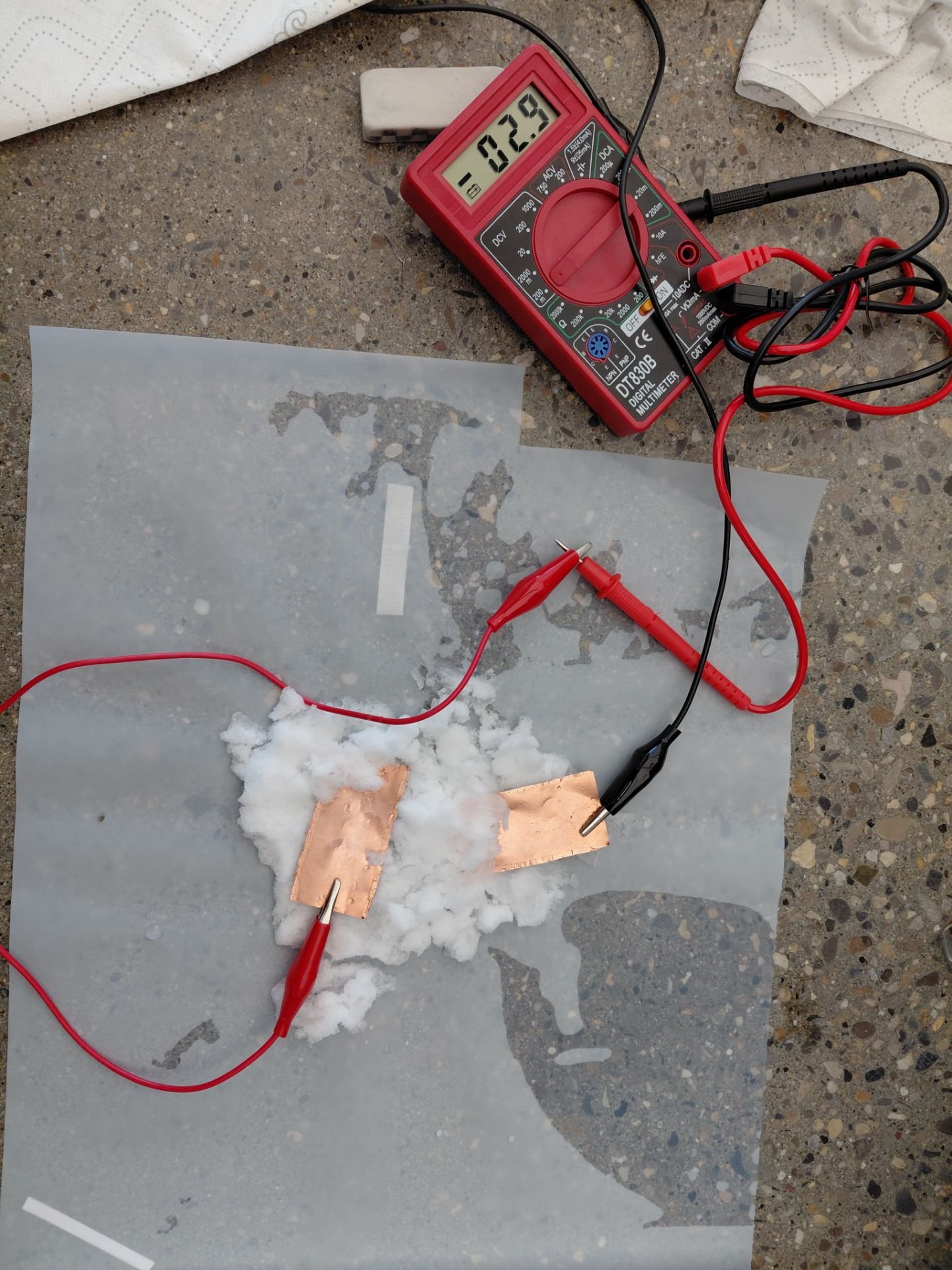 Figure 11 - Prototype 2 set-up.
Testing:
In this testing, the voltage fluctuated quite a bit and fell in a range of approximately 0.01mV - 9.5mV, depending on the movement of the snow-TENGs. There were no other observations, other than the fact that the snow-TENG remained intact and was not greatly affected by the conditions.
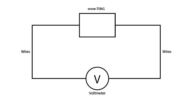
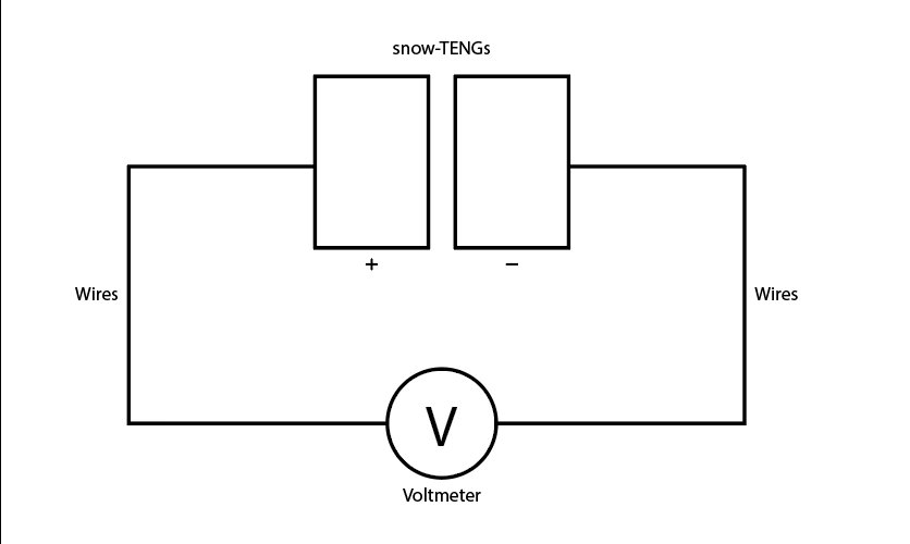
At this point, the circuit is not connected between the two TENGs except through the snow, which may have affected the result because snow is a poor conductor of electricity, and made it so that it wasn't a complete circuit.
[ Video: https://drive.google.com/file/d/1JqB6NQs_xHF7sQxvCFD8gw0tV4wv5U_D/view ]
We realized that questions would arise on whether if it truly was the snow that generated the charge and not the friction between the two snow-TENGs which prompted us to film a video of them in contact together with friction and generating no voltage.
[ Video: https://drive.google.com/file/d/1VlBBJcGmrnIHVVypFuBDgpEAiYHL1Ot-/view ]
Prototype 3:
We made a larger version, measured 10 cm by 10 cm and arranged it in the same method as Prototype 1 (reference Figure 12) and experienced nearly identical results. The theory was that a larger snow-TENG meant a larger contact surface area to collect more charge to result in a higher outcome.
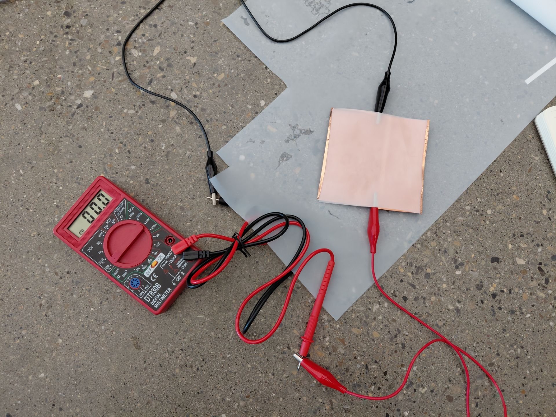 Figure 12 - Larger arrangement of Prototype 1, with a larger snow-TENG.
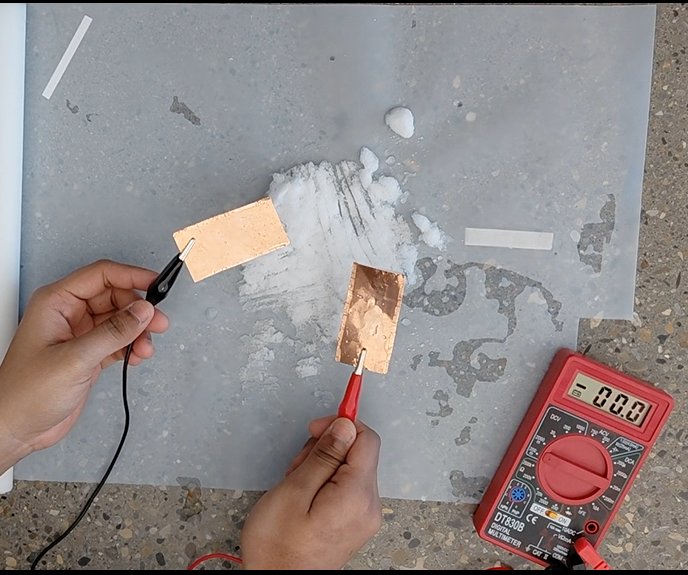
Now we created a larger version with two 10cm by 10cm sheets of PTFE and copper electrodes, and assembling it in the same way as Prototype 2, with the copper tape attaching on two parallel sides, since we were positive that a single snow-TENG did not produce results.
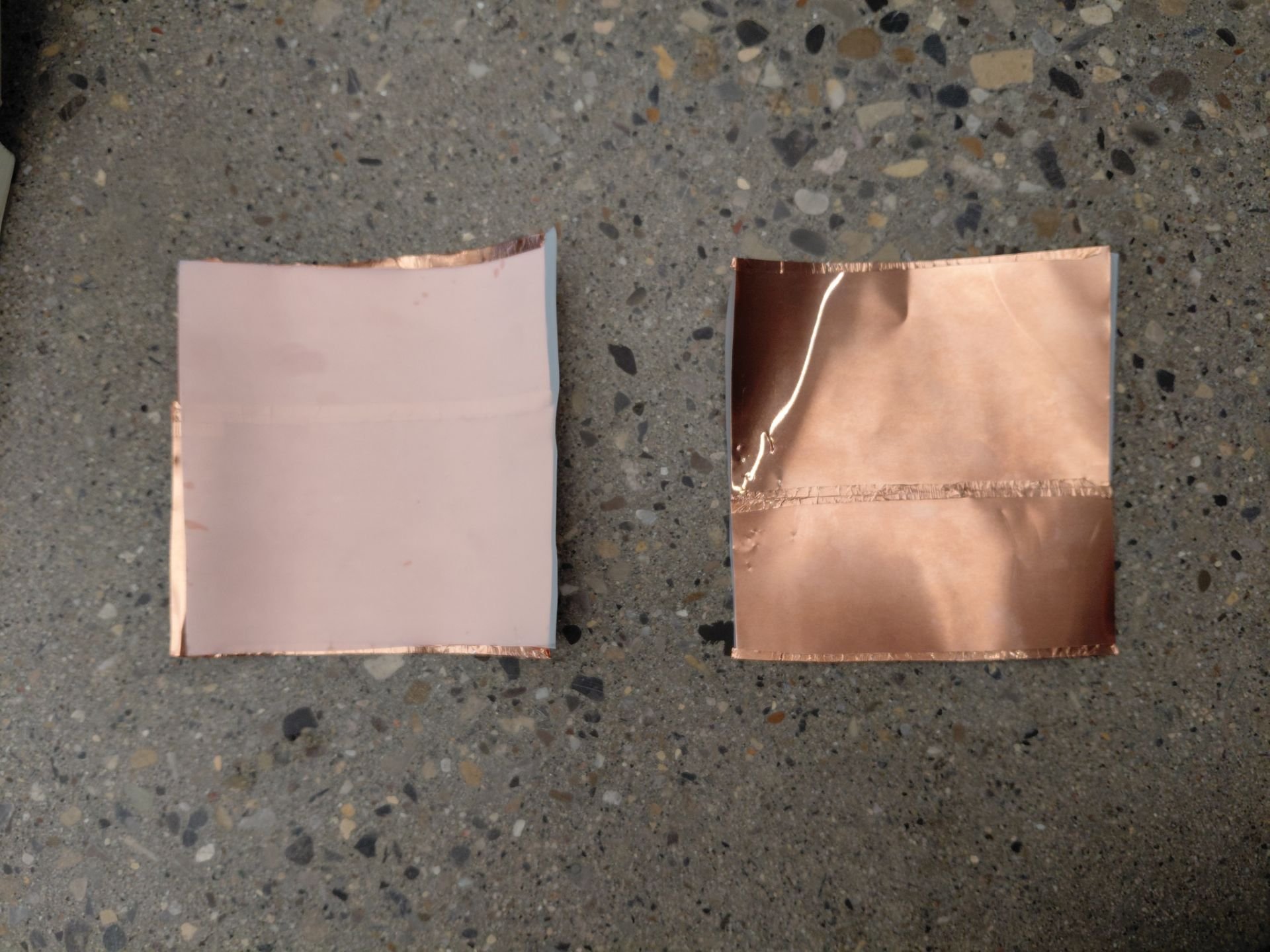 Figure 13 - Image of the front and back sides of the snow-TENGs for Prototype 3.
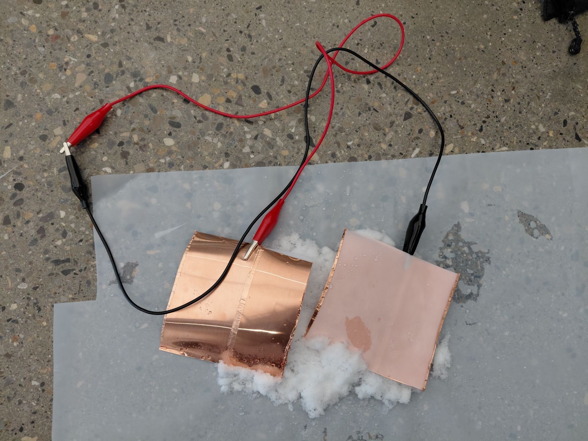 Figure 14 - Set-up for testing of Prototype 3.
Testing:
This experiment backed up the theory that a larger contact area would increase the capacity of the voltage, this time reaching approximately 0.01mV - 50mV, also demonstrate in the linked video. Similarly, it held its shape well.
[ Video: https://drive.google.com/file/d/1pvcPjbmlj0j6YhcUOZ3e9dkBJYxrzgt4/view ]
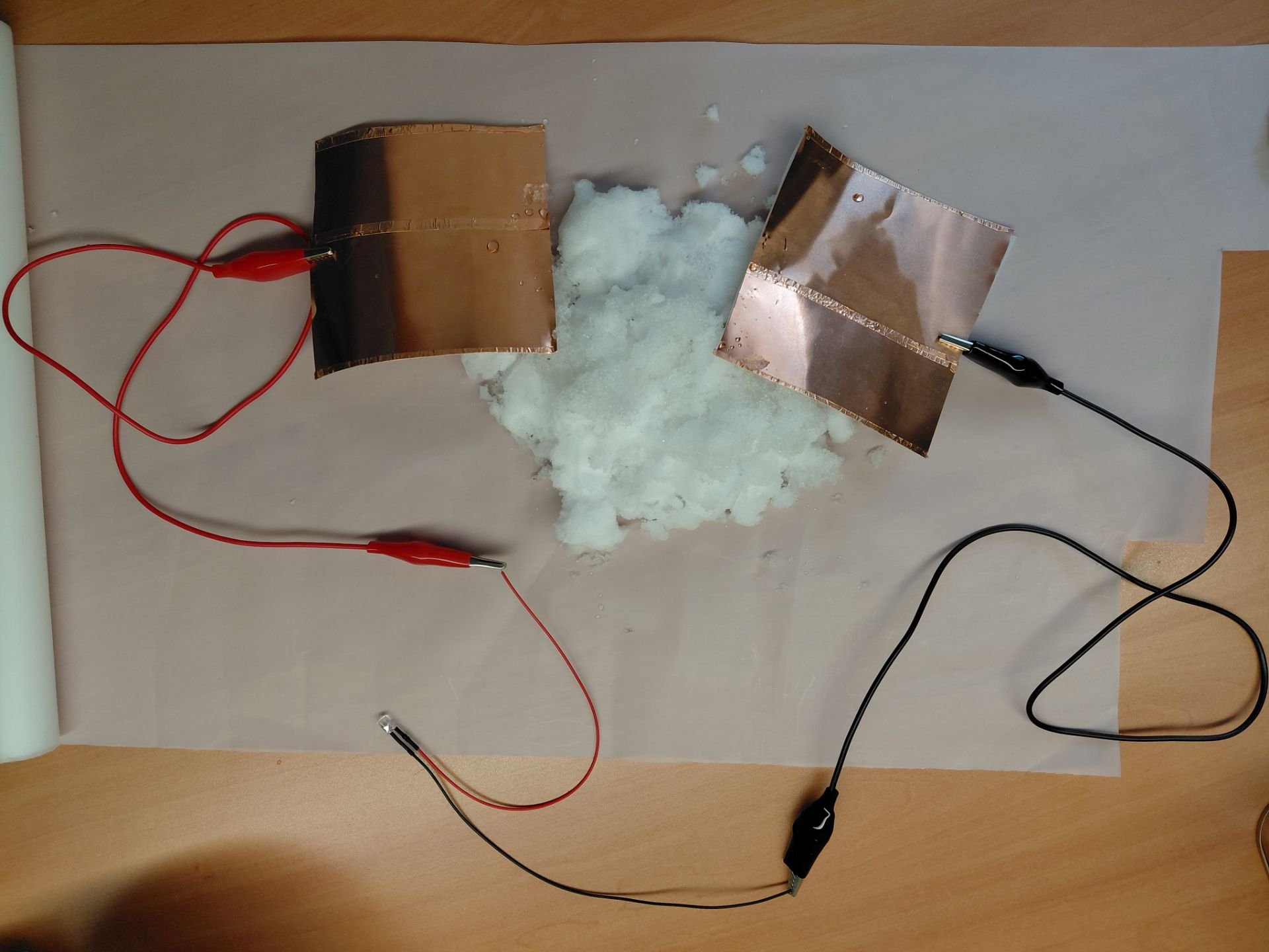
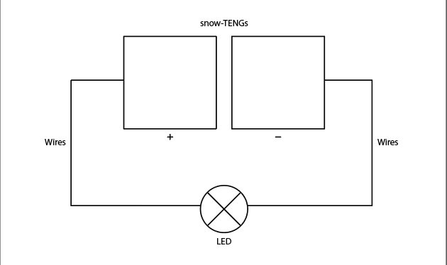
Prototype 4:
Adding on to Prototype 3, we decided to utilize another method to prove voltage by an LED light in the case that the multimeter was unreliable.
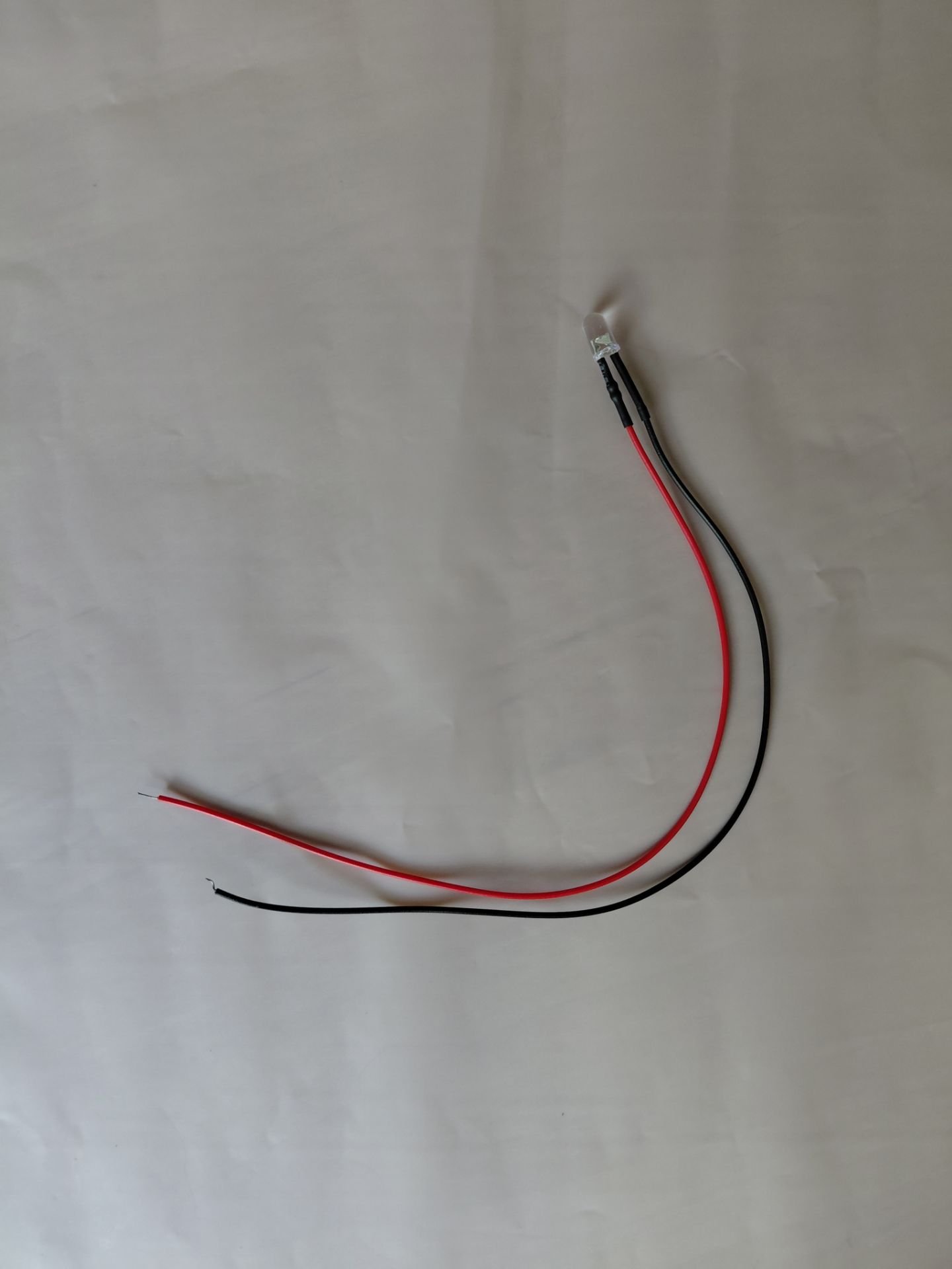 Figure 15 - The LED light added into the circuit.
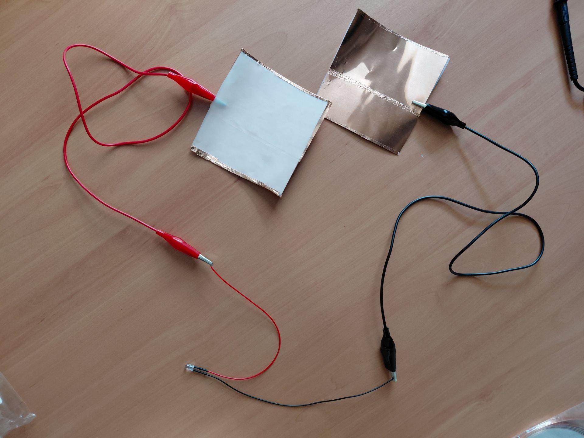
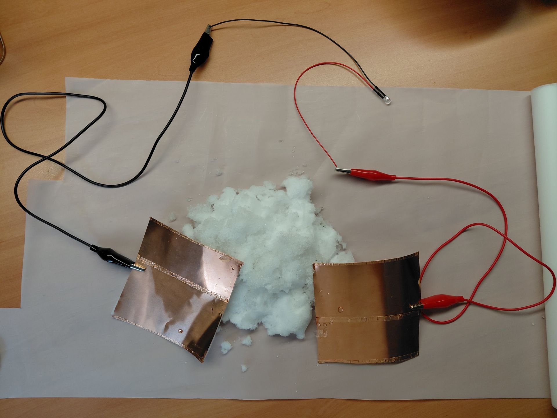 Figure 16 and 17 - Set-up for testing of Prototype 4.
Testing:
During the testing phase, the tape was likely not wide enough to maintain secure enclosure of the snow-TENG edges, and loss some attachment. This was only a slight problem and did not affect the outcome majorly. The snow-TENG results were approximately 0.01mV - 50mV, and in the same range as Prototype 3. The water was also seen intruding in between the two layers through the open ends.
[ Video: https://drive.google.com/file/d/1Q0Yw8WZemqSr3Y5jkONI5fHs41Z7J8YG/view ]
Prototype 5:
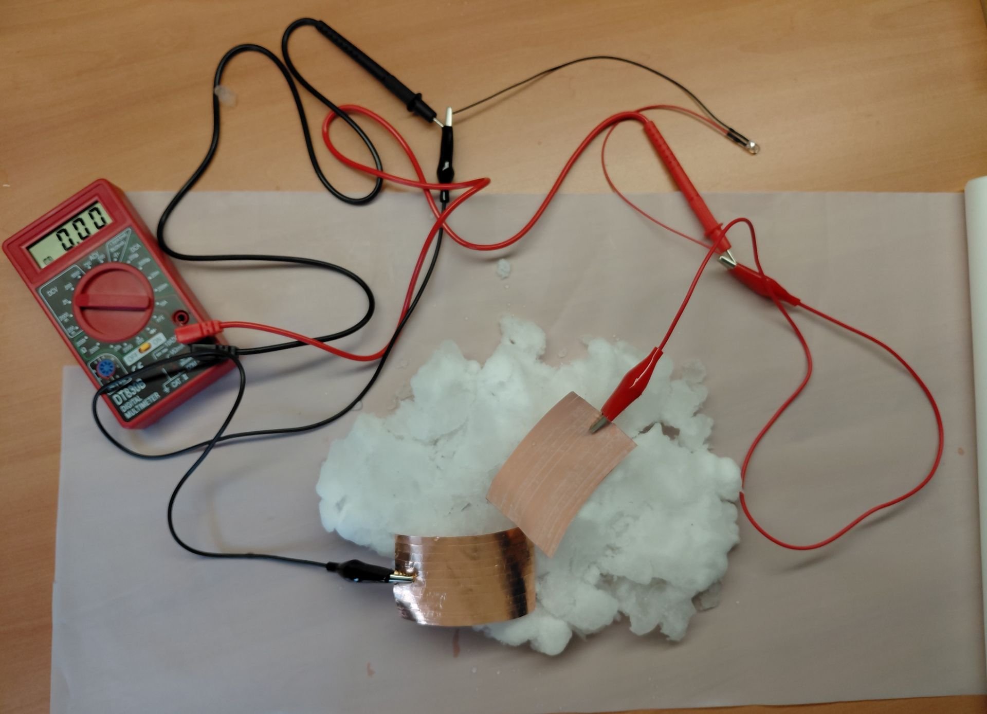
We also noticed water seeping into the gap between layers in the last prototype, which likely impeded charge transfer, and so for Prototype 5, we aimed for a closer contact surface between the triboelectric layer and electrode as a means to improve performance. To accomplish this, we substituted the copper sheet roll for the copper tape, and layered it on, ensuring no gaps. After this, using a ruler as a hard surface, the layers were smoothed out by running it down the body, tilted near a 45° angle. This works because the adhesive of the copper tape allowed for close attachment to the PTFE. Although this area was targeted much better than prior prototypes, there were still tiny gaps of air visible in between the layers and slight wrinkles in the copper tape, as shown in Figure 18.
The prototype was set up in Figure 19 like in previous experiments. In this prototype, the layers were much more flexible and in being clipped down, indents were visible.
 Figure 18 - Front and back sides of Prototype 5's snow-TENGs.
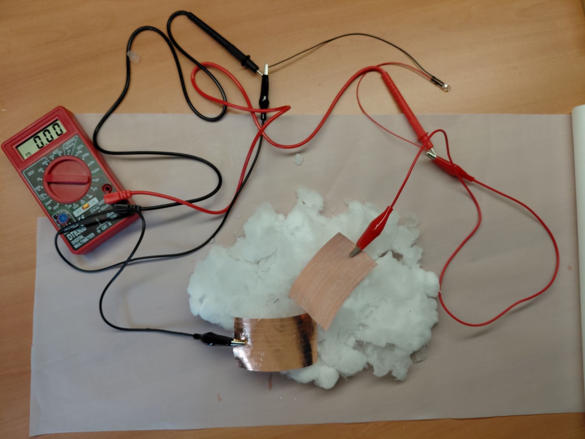 Figure 19 - Set-up for testing of Prototype 5.
Testing:
It was visible that this prototype was not as durable because of its flexibility, and was susceptible to physical distortion. And some water and rubbing caused corners of the tape to lift, likely because the adhesive was not made for water or waterproof in any means. This prototype did not fare as well, with a voltage range of approximately 0.01mV - 9.5mV.
[ Video: https://drive.google.com/file/d/1vyJXrfUPIjMnqqo4QxppgCFXqGpYAna5/view + https://drive.google.com/file/d/1eOaCFvUo-JY-9mxx6YRjs0auo64MFR46/view ]
Results
| Experiment | Changes | Resistance | Voltage |
|---|---|---|---|
| Prototype 1 | - all wires connected to one snow-TENG | 1.8Ω | 0mV |
| Prototype 2 | - two snow-TENG connected to two separate wires (+/-) | 1.8Ω | \~ 0.01mV - 9.5mV |
| Prototype 3 | - larger snow-TENG for increased surface area | 1.8Ω | \~ 0.01mV - 50mV |
| Prototype 4 | - tested energy sufficiency of snow-TENG with the incorporation of LED | 1.8Ω | \~ 0.01mV - 50mV |
| Prototype 5 | - increasing effective contact area using thinner electrode (copper tape) | 1.8Ω | \~ 0.01mV - 9.5mV |
Analysis
Experiments & Observations
Materials Used: Experiment 1
- 1 Snow-TENG (6cm x 4cm): a triboelectrification layer assembled by taping a tribo-negative PTFE, along with a thin copper electrode using copper tape.
- 2 Wires with alligator clips
- 1 Voltmeter: set to 200m DCV
- Snow: collected in -12 degree Celsius weather
 Ex.1: Attached two alligator clips on the snow-TENG, one on each side, and the other end of the wire is connected to the voltmeter.
Hypothesis: Rubbing the snow-TENG on snow will cause it to trap electrons, released by the snow through snow-electrification due to friction, and then transfer the electrons to the electrode, which will conduct it throughout the circuit to measure voltage.
Observations: No voltage changes were observed.
Materials Used: Experiment 2
- 2 Snow-TENG (6cm x 4cm): a triboelectrification layer assembled by taping a tribo-negative PTFE, along with a thin copper electrode using copper tape.
- 2 Wires with alligator clips
- 1 Voltmeter: set to 200m DCV
- Snow: collected in -12 degree Celsius weather
 Ex.2: Attached two alligator clips on two separate snow-TENG, and the other end of the wire is connected to the voltmeter.
Hypothesis: If two probes measures resistance with a positive and a negative end, then using two snow-TENGs, one on each wire, with one representing the positive terminal, and the other representing negative, energy generation should be evident.
Observations: Voltage generation observed ranged from 0.01millivolts to 9.5millivolts
Materials Used: Experiment 3
- 2 Snow-TENG (10cm x 10cm): a triboelectrification layer assembled by taping a tribo-negative PTFE, along with a thin copper electrode using copper tape.
- 2 Wires with alligator clips
- 1 Voltmeter: set to 200m DCV
- Snow: collected in -12 degree Celsius weather
 Ex.3: Attached two alligator clips on two separate, larger snow-TENGs, this iteration is to test whether the size affects energy generation, and the other end of the wire is connected to the voltmeter.
Hypothesis: The larger size of the snow-TENG would increase its surface area which would result in greater energy generation.
Observations: Voltage generation observed ranged from 0.01millivolts to 50millivolts
Materials Used: Experiment 4
- 2 Snow-TENG (10cm x 10cm): a triboelectrification layer assembled by taping a tribo-negative PTFE, along with a thin copper electrode using copper tape.
- 1 3mm LED
- 2 Wires with alligator clips
- 1 Voltmeter: set to 20 DCV
- Snow: collected in -12 degree Celsius weather
 Ex.4: Attached two alligator clips on two separate, larger snow-TENGs, this iteration is to test whether energy generated can light an LED, and the other end of the wire is connected to the LED.
Hypothesis: Increased energy generation through increased surface area should be able to light a 3mm LED.
Observations: The LED requires more energy than that the snow-TENG produces, which ranges from 0.01millivolts to 50millivolts, as no light was emitted by the diode.
Materials Used: Experiment 5
- 2 Snow-TENG (6cm x 3cm): a triboelectrification layer assembled by taping strips of copper tape on a tribo-negative PTFE ensuring it is completely covered.

- 1 LED
- 2 Wires with alligator clips
- 1 Voltmeter: set to 20 DCV
- Snow: collected in -12 degree Celsius weather
 Ex.5: Attached two alligator clips on two separate snow-TENG(made with copper tape electrode), and the other end of the wire is connected to the LED, and the voltmeter is connect between the wire and LED.
Hypothesis: Reduced distance and thickness from the tribo-negative PTFE, and the electrode should make transferring electrons efficient which can increase energy generation consistency
Observations: No consistencies in energy generation were observed as the fluctuations, nature of static electricity, in voltage remained the same as observed in 6cm x 3cm snow-TENG circuit.
Analysis + Improvements
On reflection of the testing, one of the factors that may have impacted the results was that some of the melted snow seeped in between the triboelectric layer and electrode, causing interference in the passing of charge, resulting in a less efficient process. The effective contact area was not maximized as well because of this. In subsequent experiments, methods to ensure maximum effective contact area should be employed, with possibilities of applying a force to compress the surfaces, or incorporating fillers to eliminate space and separation.
As explained in the Snow Electrification section and upon further research, there is a possibility that, "the escaping air bubbles from the melting ice particles carried negative charges to the air and left the water positively charged (Matthews & Mason, 1963)." This means that instead of the snow-TENG collecting the charges, it had been lost and it minimized the possible charges that could have been utilized. The melting snow also may have created a water layer, separating the snow-TENG surface from contact with the snow. Further testing using a procedure that tests "fresh" snow and "old" snow could prove or disprove of this theory, and further improvement can be made from there.
As presented in the five experiments above, it is evident that the snow-TENG is not a very reliable renewable energy source, especially in small sizes as it is not efficient in generating large amounts of energy to scale it. However, the end-goal of this experiment was to test whether there are any iterations or improvements that can be made in order to curate it to work in large scale electricity generations. In experiment 2, using two snow-TENGs resulted in changes of voltage. This is because the two snow-TENGs act just like a battery in a circuit, where the positive terminal (one of the snow-TENG represents the positive terminal) of the battery is connected to the negative probe, and the negative terminal (the other snow-TENG represents the negative terminal) of the battery is connected to the positive probe. This can be further explained through the process of electron transfer between the snow and the snow-TENG, as the positively charged snow-TENG (resulted from rubbing it on the snow and the transfer of electrons that happened initially from the snow-TENG to the snow) attracts and traps electrons to conduct it through the circuit, and the negatively charged snow-TENG (resulted from the energy generation in the circuit which transfers all the electrons to this snow-TENG leaving it negatively charged) repels electrons and loses it to the snow that attracts it. Evidence from these experiments supports our hypothesis such as increasing the size of the snow-TENG can increase the amount of energy generated because the size increase results in increased surface area that allows more snow particles to go through snow electrification to release electrons, and transmit it to the snow-TENG. Combining all of these observations and analysis, we can create a large scale snow-TENG that allows us to increase the surface area as much as possible to generate maximum energy from snow particles and store it in a battery, due to its static and fluctuating nature, which can then be used to power other electronic appliances or devices, and even houses.
This concept is still promising, as it is low cost and has much potential for growth, especially in cold climates or when no other energy sources are attainable. Especially because it is affordable and customizable for each condition, making it more accessible and preferrable option for lower income families residing in rural areas. Snow-TENGs unlike traditional solar panels have the ability to function during cloudy days which increases their reliability on energy generation. Aspects such as these, make it all the more possible to implement snow-TENGs and offer potential in the future as a solution, or part of a solution for energy poverty.
Conclusion
Conclusion & Possible Ideas for Large Scale Renewable Energy Generation from snow-TENGs
In conclusion, the snow-triboelectric nanogenerator is capable of producing energy in small amounts, due to the nature of static electricity, which is heavily dependent on the size, and efficiency of the snow-TENG and the materials it is composed of respectively. The maximum voltage that we were able to generate in the experiments conducted were only up to 50 millivolts. This result is however affected by various factors including the quality and the similarity of the materials used as we opted to use the materials listed due to affordability and accessibility. The performance of the substituted, cheaper materials, we were not able to accurately determine the efficiency or the effectiveness of a snow-TENG. However, we were able to produce a theory using the results from the experiments we conducted, that can possibly help in large scale energy generations from snow-TENGs. We have generated a few ideas including attaching snow-TENGs to snow-shovel machines, and grain bins by taking into consideration the factors that are crucial for a snow-TENG to function, which includes snow particles creating constant friction, and the circuits that will be attached to a energy storage device such as a battery. This battery can then be used for various small scale electricity needs, which can reduce the household's overall utility expenses making it affordable for them to invest in necessary electrical needs such as a sufficient heating system.
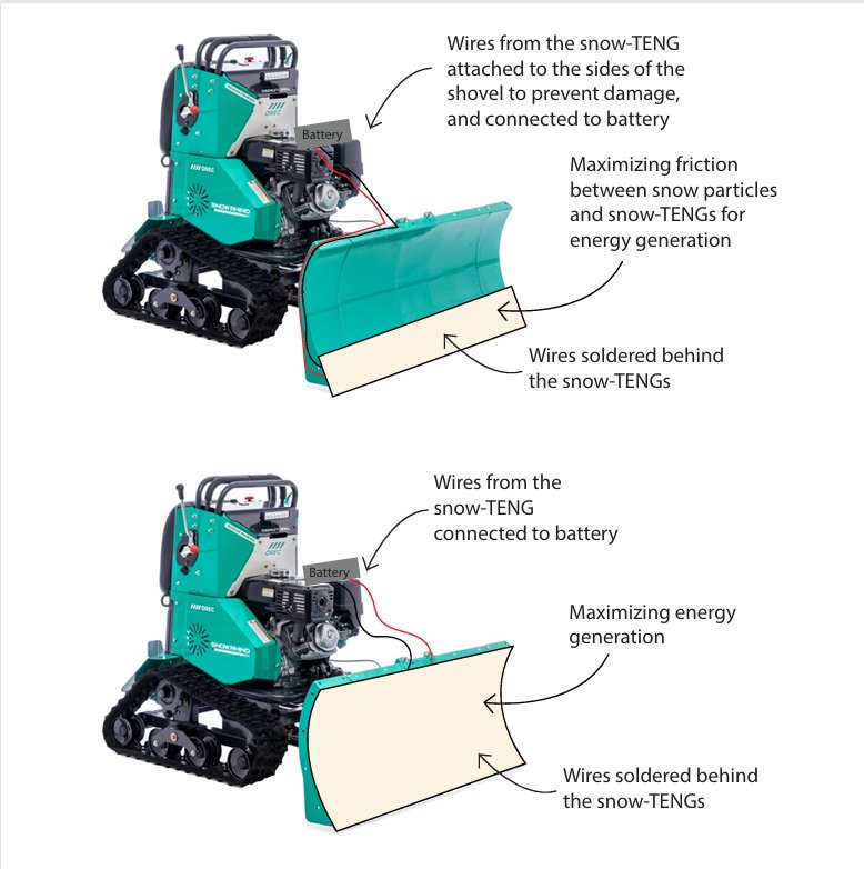
Snow-Shovel Machines:
Attaching the snow-TENGs on top at the edge of the shovel of the snow shovel machine allows maximum friction between the snow particles and the snow-TENG as the snow swirls on the shovel when pushed. The snow-TENGs will have wires that are soldered to the electrodes, connecting them and allowing electricity to transmit across all the snow-TENGs and reach the battery. Installing this snow-TENG circuit onto the surface of the shovel will help maximize the energy generation as well.
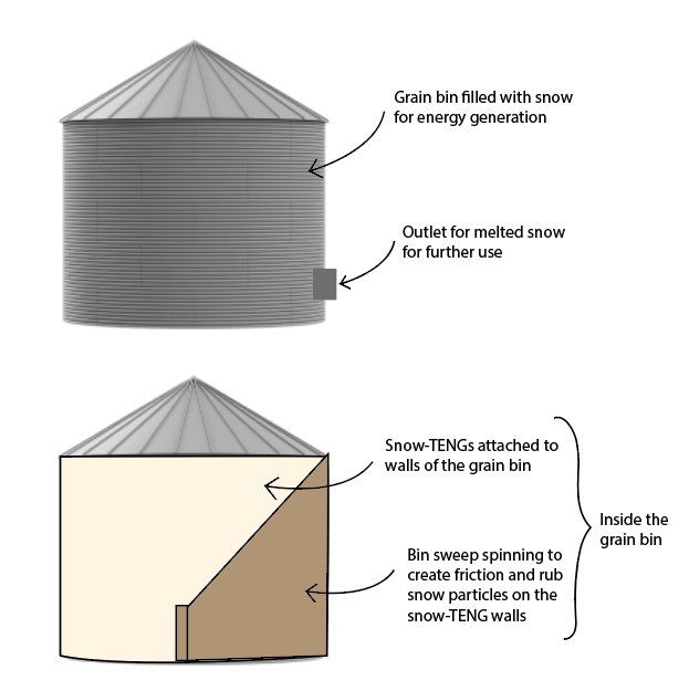
Grain Bins:
Grain bins are another rural friendly, large scale installation that can utilize snow-TENGs for large scale renewable energy generation. Attaching snow-TENGs to the walls of the grain bin creates a large surface area for greater energy generation. The process of energy generation would include, the filling of the grain bin that is covered in snow-TENGs with snow, the spinning of the bin sweep to create friction and rub against the snow-TENG walls for energy generation, and finally the manual outlet (that will be attached to the bottom of the bin) to release the melted snow, which can then be used for various purposes including, filtration for drinking water, water for crops, etc. However, direct electricity connections cannot be given due to the static fluctuating electricity. To solve this we need to store the electricity that is generated in other energy storage systems.
Citations
Energy Poverty
- Moore, N., & Zavarella, J. (2017). ENERGY POVERTY IN INDIGENOUS COMMUNITIES. Harrowsmith, 38–40. https://uwaterloo.ca/waterloo-institute-sustainable-energy/sites/default/files/uploads/documents/harrowsmith_energy_article.pdf
- Riva, M., Makasi, S. K., Dufresne, P., O’Sullivan, K., & Toth, M. (2021). Energy poverty in Canada: Prevalence, social and spatial distribution, and implications for research and policy. Energy Research & Social Science, 81, 102237. https://doi.org/10.1016/j.erss.2021.102237
- Ritchie, H., Rosado, P., & Roser, M. (2019, September 20). Access to energy. Our World in Data. https://ourworldindata.org/energy-access
- Angeletopoulou, P., Sardianou, E., Damigos, D., & Kostakis, I. (2025). Energy poverty and severe material deprivation in Greece: A path to inclusive policy solutions. Environmental Challenges. https://doi.org/10.1016/j.envc.2025.101301
- European rural areas face higher levels of energy poverty. (2025, June 26). Joint Research Centre. https://joint-research-centre.ec.europa.eu/jrc-news-and-updates/european-rural-areas-face-higher-levels-energy-poverty-2025-06-26_en
Snow-TENG
- Ahmed, A., Hassan, I., Mosa, I. M., Elsanadidy, E., Phadke, G. S., El-Kady, M. F., Rusling, J. F., Selvaganapathy, P. R., & Kaner, R. B. (2019). All printable snow-based triboelectric nanogenerator. Nano energy, 60, 17–25. https://doi.org/10.1016/j.nanoen.2019.03
- Akram, W., Chen, Q., Xia, G., & Fang, J. (2022). A review of single electrode triboelectric nanogenerators. Nano Energy, 106, 108043. https://doi.org/10.1016/j.nanoen.2022.108043
- Bai, Y., Feng, H., & Li, Z. (2022). Theory and applications of high-voltage triboelectric nanogenerators. Cell Reports Physical Science. https://doi.org/10.1016/j.xcrp.2022.101108
- Kim, E., & Kim, E. (2023, February 7). How can we find out how much snow is in the world?. https://eos.org/science-updates/how-can-we-find-out-how-much-snow-is-in-the-world
Material Selection
- Mondal, A., Faraz, M., Dahiya, M., Khare, N. (2024, August, 17). Double-Layer Electronegative Structure-Based Triboelectric Nanogenerator for Enhanced Performance Using Combined Effect of Enhanced Charge Generation and Improved Charge Trapping. ACS Applied Materials & Interfaces, https://pubs.acs.org/doi/10.1021/acsami.4c08964
- Dejene, B.K., Melese, A.Y. (2025, August, 12). Textile-based triboelectric nanogenerators: A critical review of materials, fabric designs, and washability for wearable applications. Department of Textile Engineering, Institute of Technology, Hawassa University, Hawassa, Ethiopia. https://doi.org/10.1016/j.jsamd.2025.100975
Contact Triboelectrification
- https://www.sciencedirect.com/topics/physics-and-astronomy/triboelectrification
- Tian, J., He, Y., Li, F., Peng, W., & He, Y. (2024, December, 6). On the mechanism of contact electrification: a comprehensive review. Journal of Materials Chemistry A. https://doi.org/10.1039/d4ta07756c
- PAN S, ZHANG Z. Fundamental theories and basic principles of triboelectric effect: A review. Friction, 2019, 7(1): 2-17. https://doi.org/10.1007/s40544-018-0217-7
- Xu, C., Zi, Y., Wang, A. C., Zou, H., Dai, Y., He, X., Wang, P., Wang, Y.-C., Feng, P., Li, D., & Wang, Z. L. (2018). On the Electron-Transfer Mechanism in the Contact-Electrification Effect. Advanced Materials, 30(15), 1706790. https://doi.org/10.1002/adma.201706790
- Wang, Z. L., Wang, A. C. (2019). On the origin of contact-electrification. Materials Today. https://doi.org/10.1016/j.mattod.2019.05.016
- Castro, A., Chen, W., Heraldez, J., & Nguyen, B. (n.d.). Study of Triboelectrification on Insulator Materials. https://scholarworks.calstate.edu/downloads/w0892d13v
Charge Retention and Charge Loss
- Wang, J., Zhang, B., Zhao, Z., Gao, Y., Liu, D., Liu, X., Yang, P., Guo, Z., Wang, Z.L., Wang, J. (2023, December 31). Boosting the Charge Density of Triboelectric Nanogenerator by Suppressing Air Breakdown and Dielectric Charge Leakage. https://doi.org/10.1002/aenm.202303874
- Wang, Y., Jin, X., Wang, W., Niu, J., Zhu, Z., Lin, T. (2021, January 30). Efficient Triboelectric Nanogenerator (TENG) Output Management for Improving Charge Density and Reducing Charge Loss. 10.1021/acsaelm.0c00890
- Liu, D., Zhou, L., Gao, Y., Liu, D., Qiao, W., Shi, J., Liu, X., Zhao, Z., Wang, Z. L., & Wang, J. (2024). Interface charge regulation enhancing output and durability of triboelectric nanogenerator for efficient wastewater treatment. Advanced Energy Materials. https://doi.org/10.1002/aenm.202401958
- Xichen Yin, Zhou Chen, Hui Chen, et al. Optimization strategy of triboelectric nanogenerators for high humidity environment service performance. Authorea. (August 29, 2024). https://doi.org/10.22541/au.172493400.02518413/v1
- Wang, Y., Jin, X., Wang, W., Niu, J., Zhu, Z., & Lin, T. (2021). Efficient triboelectric Nanogenerator (TENG) output management for improving charge density and reducing charge loss. ACS Applied Electronic Materials. https://doi.org/10.1021/acsaelm.0c00890
- Munirathinam, K., Li, L., Shanmugasundaram, A. et al. Air-Breakdown Triboelectric Nanogenerator Inspired by Transistor Architecture for Low-Force Human–Machine Interfaces. Nano-Micro Lett. 18, 251 (2026, Febuary 11). https://doi.org/10.1007/s40820-026-02103-0
Performance Improvements
- https://www.sciencedirect.com/topics/earth-and-planetary-sciences/doping-materials
- Park, SJ., Seol, ML., Jeon, SB. et al. Surface Engineering of Triboelectric Nanogenerator with an Electrodeposited Gold Nanoflower Structure. Sci Rep 5, 13866 (2015). https://doi.org/10.1038/srep13866
- Abdoli, H., & Leung, S. N. (2018). Polymeric Triboelectric Nanogenerator: Effects of polymer type, geometry, and porosity on triboelectrification. Progress in Canadian Mechanical Engineering. https://doi.org/10.25071/10315/35308
- Suo, X., Li, B., Ji, H., Mei, S., Miao, S., Gu, M., Yang, Y., Jiang, D., Cui, S., Chen, L., Chen, G., Wen, Z., & Huang, H. (2023). Dielectric layer doping for enhanced triboelectric nanogenerators. Nano Energy, 114, 108651. https://doi.org/10.1016/j.nanoen.2023.108651
- Okbaz, A., Karabiber, A., Yar, A., Kınas, Z., Sarılmaz, A., & Ozel, F. (2021). High-performance triboelectric nanogenerator with optimized Al or Ti-embedded silicone tribomaterial. Energy Conversion and Management, 252, 115053. https://doi.org/10.1016/j.enconman.2021.115053
- Rahman, M. T., Kim, Y., Rahman, M. S., Lim, J. Y., & Kim, S. (2025). Bimetallic nanoporous carbon-based direct-current triboelectric nanogenerators for biomechanical energy harvesting and sensing. Chemical Engineering Journal, 519, 164938. https://doi.org/10.1016/j.cej.2025.164938
- Potu, S., Kulandaivel, A., Gollapelli, B., Khanapuram, U. K., & Rajaboina, R. K. (2024). Oxide based triboelectric nanogenerators: Recent advances and future prospects in energy harvesting. Materials Science and Engineering R Reports, 161, 100866. https://doi.org/10.1016/j.mser.2024.100866
- Gu, D., Luo, H., Gao, S., Li, Z., Chen, S., & Zhou, S. (2024). Preparation of the superhydrophobic polytetrafluoroethylene (PTFE) surface by doped copper to alter microtexture characteristics. Materials Letters, 372, 137071. https://doi.org/10.1016/j.matlet.2024.137071
- AZoM. (2023, May 26). How does doping affect the conductivity of a semiconductor? https://www.azom.com/article.aspx?ArticleID=22714#:\~:text=P%2Dtype%20semiconductors%20are%20created,forming%20the%20desired%20dopant%20concentration.
- The Complete Guide to Doping in Semiconductors: What Is it and Why Is it Necessary? (n.d.). https://www.waferworld.com/post/the-complete-guide-to-doping-in-semiconductors-what-is-it-and-why-is-it-necessary
- Venkatesan, H.M., Arun, A.P. (2025). High-performance triboelectric nanogenerators based on Ag-doped ZnO loaded electrospun PVDF nanofiber mats for energy harvesting and healthcare monitoring. Sci Rep 15, 3347. https://doi.org/10.1038/s41598-025-87148-8
- Xu, G., Zhao, Z., Wang, Z. L., & Li, H. (2025). Integrating machine learning with triboelectric nanogenerators: Optimizing electrode materials and doping strategies for intelligent energy harvesting. Nano Energy. https://doi.org/10.1016/j.nanoen.2025.111131
- Huang, Y. J., Chuang, J. I., & Chung, C. K. (2025). Enhancing the Output Performance of Fiber-TENG Through Graphite Doping and Its Application in Human Motion Sensing. Sensors (Basel, Switzerland), 25(20), 6409. https://doi.org/10.3390/s25206409
- Pan, J., & Jin, A. (2024). Improvement of output performance of the TENG based on PVDF by doping Tourmaline. ACS Sustainable Chemistry & Engineering, 12(5), 2092–2099. https://doi.org/10.1021/acssuschemeng.3c07586
- Suo, X., Li, B., Ji, H., Mei, S., Miao, S., Gu, M., Yang, Y., Jiang, D., Cui, S., Chen, L., Chen, G., Wen, Z., & Huang, H. (2023). Dielectric layer doping for enhanced triboelectric nanogenerators. Nano Energy, 114, 108651. https://doi.org/10.1016/j.nanoen.2023.108651
- Rajasekar, M., & Sivakumar, M. (2025). Recent trends and future perspectives of triboelectric nanogenerators (TENGs) and applications. RSC advances, 15(57), 49600–49642. https://doi.org/10.1039/d5ra06645j
- Cao, V. A., Kim, M., Lee, S., Van, P. C., Jeong, J., Park, P., & Nah, J. (2022). Chemically modified MXene nanoflakes for enhancing the output performance of triboelectric nanogenerators. Nano Energy, 107, 108128. https://doi.org/10.1016/j.nanoen.2022.108128
- Zhang, R., Örtegren, J., Hummelgård, M., Olsen, M., Andersson, H., & Olin, H. (2022). A review of the advances in composites/nanocomposites for triboelectric nanogenerators. Nanotechnology. https://doi.org/10.1088/1361-6528/ac4b7b
- Choi, G.-J., Sohn, S.-H., Kim, S.-J., & Park, I.-K. (2025). Polymer Composite-Based Triboelectric Nanogenerators: Recent Progress, Design Principles, and Future Perspectives. Polymers, 17(14), 1962. https://doi.org/10.3390/polym17141962
- Rahul, T. P., & Sreekanth, P. S. R. (2025). Synergies in Materials and Manufacturing: A Review of Composites and 3D Printing for Triboelectric Energy Harvesting. Journal of Composites Science, 9(8), 386. https://doi.org/10.3390/jcs9080386
- Dou, L., Lin, Y. H., & Nan, C. W. (2021). An Overview of Linear Dielectric Polymers and Their Nanocomposites for Energy Storage. Molecules (Basel, Switzerland), 26(20), 6148. https://doi.org/10.3390/molecules26206148
- Libretexts. (2021, September 8). Conductive polymers. Engineering LibreTexts. https://eng.libretexts.org/Bookshelves/Materials_Science/Supplemental_Modules_(Materials_Science)/Materials_and_Devices/Conductive_Polymers
PTFE (Polytetrafluoroethylene):
- Zhang, R., Olin, H. (2020, October, 27), Material choices for triboelectric nanogenerators: A critical review. Wiley Online Library. https://onlinelibrary.wiley.com/doi/10.1002/eom2.12062
- Zhao, Z., Zhou, L., Li, S. et al. Selection rules of triboelectric materials for direct-current triboelectric nanogenerator. Nat Commun 12, 4686 (2021). https://doi.org/10.1038/s41467-021-25046-z
- Kintek. (2026, February, 10). Why Is PTFE Considered Chemically Inert? The Molecular Secret To Ultimate Chemical Resistance. https://kintek-solution.com/faqs/why-is-ptfe-considered-chemically-inert
- Kintek. (2026, February, 10). What Is The Reactivity Of PTFE And Why Is It Inert? Discover The Science Behind Its Unmatched Chemical Resistance. https://kintek-solution.com/faqs/what-is-the-reactivity-of-ptfe-and-why-is-it-inert
- Kintek. (2026, February, 10). What Makes The PTFE Bottle Durable? Unmatched Chemical & Thermal Stability For Demanding Applications. https://kintek-solution.com/faqs/what-makes-the-ptfe-bottle-durable
- Kintek. (2026, February, 10). Why Are PTFE Vials Considered Environmentally Friendly? Reduce Lab Waste With Durable Reusables. https://kintek-solution.com/faqs/why-are-ptfe-vials-considered-environmentally-friendly
- Smith, H. (2022, March, 3) What is PTFE? Polytetrafluoroethylene. https://enkidupolymers.com/what-is-ptfe/
- Lee, J.W., Ye, B.u., Baik, J.M. (2017, March, 29). Research Update: Recent progress in the development of effective dielectrics for high-output triboelectric nanogenerator. https://www.researchgate.net/publication/315903559_Research_Update_Recent_progress_in_the_development_of_effective_dielectrics_for_high-output_triboelectric_nanogenerator
- Yu, Aifang & Zhu, Yaxing & Wang, Wei. (2019). Progress in Triboelectric Materials: Toward High Performance and Widespread Applications. Advanced Functional Materials. 29. 1900098. 10.1002/adfm.201900098.
- Suko, PTFE Machinery. (2023, March, 2). Understanding the Hydrophobic Properties of PTFE. https://ptfe-machinery.com/understanding-the-hydrophobic-properties-of-ptfe/
- Zhao, Z., Zhou, L., Li, S. et al. Selection rules of triboelectric materials for direct-current triboelectric nanogenerator. Nat Commun 12, 4686 (2021). https://doi.org/10.1038/s41467-021-25046-z
- Paosangthong, W., Torah, R., & Beeby, S. (2017). Performance Comparison between Different Materials and Operation Modes of Triboelectric Nanogenerator. In University of Southampton, School of Electronics and Computer Science. https://www.enerharv.com/wp-content/uploads/pub_uploads/2018/06/05-EH2018-SOUTHAMPTON-PAOSANGTHONG-POSTER-PDF-TO-POST-6-13-18.pdf
Friction on Snow and Ice [with mention of PTFE]
- Bowden, F. P. (1953). Friction on snow and ice. Proceedings of the Royal Society of London a Mathematical and Physical Sciences, 217(1131), 462–478. https://doi.org/10.1098/rspa.1953.0074
Electrode:
- Farmer’s Copper Ltd. (n.d.). Copper Metals Exceptional Resistance to Corrosion. Farmers Copper, LTD. https://www.farmerscopper.com/blog/copper-metals-exceptional-resistance-to-corrosion.html
- Team, O. (2025, March 21). Understanding the corrosion resistance of copper. Okon Recycling. https://www.okonrecycling.com/industrial-scrap-metal-recycling/copper-recovery/corrosion-resistance-of-copper/
- How long does copper last outside? (n.d.). Mead Metals, Inc. https://www.meadmetals.com/blog/how-long-does-copper-last-outside
- Helmenstine, A.M.. (2024, May 12). A Table of Electrical Conductivity and Resistivity of Common Materials. ThoughtCo. https://www.thoughtco.com/table-of-electrical-resistivity-conductivity-608499
- Fundamentals: Types of Copper and Properties. (2019). Copper.org. https://www.copper.org/applications/architecture/arch_dhb/technical-discussion/fundamentals/intro.html
- Xia, K., Xu, Z., Zhu, Z., Zhang, H., & Nie, Y. (2019). Cost-Effective Copper⁻Nickel-Based Triboelectric Nanogenerator for Corrosion-Resistant and High-Output Self-Powered Wearable Electronic Systems. Nanomaterials (Basel, Switzerland), 9(5), 700. https://doi.org/10.3390/nano9050700
- Shateri, A. A. A., Fatah, S. K., Zhuo, F., Shuaibu, N. S., Chen, C., Wan, R., & Wang, X. (2025). Constant High-Voltage Triboelectric Nanogenerator with Stable AC for Sustainable Energy Harvesting. Micromachines, 16(7), 801. https://doi.org/10.3390/mi16070801
- Bagchi, B., Datta, P., Fernandez, C. S., Gupta, P., Jaufuraully, S., David, A. L., Siassakos, D., Desjardins, A., & Tiwari, M. K. (2023). Flexible triboelectric nanogenerators using transparent copper nanowire electrodes: energy harvesting, sensing human activities and material recognition. Materials horizons, 10(8), 3124–3134. https://doi.org/10.1039/d3mh00404j
- Aazem, I., Mathew, D. T., Radhakrishnan, S., Vijoy, K. V., John, H., Mulvihill, D. M., & Pillai, S. C. (2022). Electrode materials for stretchable triboelectric nanogenerator in wearable electronics. RSC advances, 12(17), 10545–10572. https://doi.org/10.1039/d2ra01088g
- Gnanaseelan, N., Pabba, D. P., Acuña-Ureta, D. E., Fischerauer, G., Tremmel, S., & Marian, M. (2025). Two-dimensional layered materials for triboelectric nanogenerators. Progress in Materials Science, 158, 101622. https://doi.org/10.1016/j.pmatsci.2025.101622
- Tang, W., Jiang, T., Fan, F. R., Yu, A. F., Zhang, C., Cao, X., & Wang, Z. L. (2015). Liquid‐Metal electrode for High‐Performance triboelectric nanogenerator at an instantaneous energy conversion efficiency of 70.6%. Advanced Functional Materials. https://doi.org/10.1002/adfm.201501331
- Pace, G., Ansaldo, A., Serri, M., Lauciello, S., & Bonaccorso, F. (2020). Electrode selection rules for enhancing the performance of triboelectric nanogenerators and the role of few-layers graphene. Nano Energy. https://doi.org/10.1016/j.nanoen.2020.104989
- Zhu, S., Xia, Y., Zhu, Y., Wu, M., Jia, C., & Wang, X. (2022). High-performance triboelectric nanogenerator powered flexible electroluminescence devices based on patterned laser-induced copper electrodes for visualized information interaction. Nano Energy. https://doi.org/10.1016/j.nanoen.2022.107116
Snow Electrification:
- Latham, J. & Stow, C.. (1965). The Electrification of Blowing Snow. Journal of the Meteorological Society of Japan. Ser. II. 43. 23-29. 10.2151/jmsj1965.43.1_23.
- SCHMIDT, D. S., SCHMIDT, R. A., DENT, J. D. (1999, March, 29) ELECTROSTATIC FORCE IN BLOWING SNOW. https://user-web.icecube.wisc.edu/\~araproject/radio/open/snow-electrostatic.pdf
- Latham, J. & Stow, C.. (1967, January). A laboratory investigation of the electrification of snowstorms. https://rmets.onlinelibrary.wiley.com/doi/abs/10.1002/qj.49709339505
- Tkachenko, K., Jacobi, H. (2024, January, 20). Electrical charging of snow and ice in polar regions and the potential impact on atmospheric chemistry. https://pubs.rsc.org/en/content/articlelanding/2024/ea/d3ea00084b
- J. Latham, Basil John Mason; Electric charge transfer associated with temperature gradients in ice. Proc. A 1 March 1961; 260 (1303): 523–536. https://doi.org/10.1098/rspa.1961.0051
- Nakaya, U.; Terada, T. (1934, December, 25). On the Electrical Nature of Snow Particles. Hokkaido University. https://hdl.handle.net/2115/34450
- National Snow and Ice Data Center. (n.d.). Science of Snow. https://nsidc.org/learn/parts-cryosphere/snow/science-snow
- Zhang, H., De Poorter, J., Mukherjee, R., Boreyko, J. B., Qiao, R. (2021). Thermoelectrics in ice slabs: charge dynamics and thermovoltages. Physical Chemistry Chemical Physics. https://doi.org/10.1039/d1cp02304g
- Petrenko, V.F., et al., p. 27-28, (1993, August). Electrical Properties of Ice. US Army Corps of Engineers Cold Regions Research & Engineering Laboratory. https://apps.dtic.mil/sti/tr/pdf/ADA270432.pdf
- Glen JW, Paren JG. The Electrical Properties of Snow and Ice. Journal of Glaciology. 1975;15(73):15-38. doi:10.3189/S0022143000034249
Effects of Thickness (not checked)
- Alghamdi, M. S., Morgan, J. J., Walsh, K., Shin, D. W., Nigmatullin, R., Saadi, Z., Routledge, J., Neves, A. I., Russo, S., Eichhorn, S. J., & Craciun, M. F. (2025). Triboelectric nanogenerator based on cellulose nanocrystals and graphene for energy harvesting from piano playing motion. Nano Energy. https://doi.org/10.1016/j.nanoen.2025.110816
- Maamoun, A. A., Mahmoud, A. A., Naeim, D. M., Arafa, M., & Esawi, A. M. K. (2024). Effect of density and thickness of flexible polyurethane foam on the performance of triboelectric nanogenerators. Materials Advances. https://doi.org/10.1039/d4ma00304g
- Anekar, N., Selmokar, P., & Satpute, N. (2025). Performance analysis of lateral sliding mode triboelectric nanogenerators for self-powered healthcare applications. Journal of Electrostatics, 135, 104074. https://doi.org/10.1016/j.elstat.2025.104074
- Liu, C., Cui, S., Li, L., Zhao, Z., Li, H., Miao, J., Wang, Y., Tan, L., Wu, J., Lan, H., & Wang, J. (2025). Structural design and performance study of sunny/rainy adaptive triboelectric nanogenerators for self-powered coating thickness sensing. Colloids and Surfaces a Physicochemical and Engineering Aspects, 733, 139308. https://doi.org/10.1016/j.colsurfa.2025.139308
- Gomes, A., Rodrigues, C., Pereira, A. M., & Ventura, J. (2018). Influence of thickness and contact area on the performance of PDMS-Based Triboelectric nanogenerators. arXiv (Cornell University). https://doi.org/10.48550/arxiv.1803.10070
- Okbaz, A., Karabiber, A., Yar, A., Kınas, Z., Sarılmaz, A., & Ozel, F. (2021b). High-performance triboelectric nanogenerator with optimized Al or Ti-embedded silicone tribomaterial. Energy Conversion and Management. https://doi.org/10.1016/j.enconman.2021.115053
- Zhang, Z., Sun, X., Chen, Y., Debeli, D. K., & Guo, J. (2018). Comprehensive dependence of triboelectric nanogenerator on dielectric thickness and external impact for high electric outputs. Journal of Applied Physics. https://doi.org/10.1063/1.5031809
- Kim, D., Kim, W., Jin, I. K., Park, H., Im, S., & Choi, Y. (2019). A study of the charge distribution and output characteristics of an ultra-thin tribo-dielectric layer. Nano Energy. https://doi.org/10.1016/j.nanoen.2019.05.070
- Zhang, Zhi & Sun, Xiongfei & Chen, Ying & Debeli, Dereje & Guo, Jiansheng. (2018). Comprehensive dependence of triboelectric nanogenerator on dielectric thickness and external impact for high electric outputs. Journal of Applied Physics. 124. 045106. 10.1063/1.5031809.
- Zhang, Zhi & Sun, Xiongfei & Chen, Ying & Debeli, Dereje & Guo, Jiansheng. (2018). Comprehensive dependence of triboelectric nanogenerator on dielectric thickness and external impact for high electric outputs. Journal of Applied Physics. 124. 045106. 10.1063/1.5031809.
- Liu, D., Zhou, L., Cui, S., Gao, Y., Li, S., Zhao, Z., Yi, Z., Zou, H., Fan, Y., Wang, J., & Wang, Z. L. (2022). Standardized measurement of dielectric materials' intrinsic triboelectric charge density through the suppression of air breakdown. Nature communications, 13(1), 6019. https://doi.org/10.1038/s41467-022-33766-z
- Zheng, Z., Li, L., Liu, M., Wang, L., Yang, R., Li, R., Wang, L., Zheng, H., & Zheng, Y. (2025). Enhancing Triboelectric Nanogenerator Performance via Ultraviolet Nanosecond Laser-Engineered Microstructured Intermediate Layer. ACS applied materials & interfaces, 17(39), 54888–54904.
Anti-icing
- Lolla, V. Y., Zhang, H., Socha, B. Z., Qiao, R., & Boreyko, J. B. (2025). Electrostatic Defrosting. Small methods, 9(12), e01143. https://doi.org/10.1002/smtd.202501143
- Kreder, M., Alvarenga, J., Kim, P. et al. (2016). Design of anti-icing surfaces: smooth, textured or slippery?. Nat Rev Mater 1, 15003. https://doi.org/10.1038/natrevmats.2015.3
Google Drive Link to Images and Videos:
https://drive.google.com/file/d/1JqB6NQs_xHF7sQxvCFD8gw0tV4wv5U_D/view?usp=sharing
Xu, L., Xue, L., & Geresdi, I. (2020). How does the melting impact charge separation in Squall Line? A Bin microphysics simulation study. Geophysical Research Letters. https://doi.org/10.1029/2020gl090840
Snow-Shovel Machine Image:
- SNOW RHINO. (n.d.). Les Entreprises Denis Boisvert Inc. https://www.amidenis.com/en/snowblowers/motorised-snow-plow/snow-rhino
Acknowledgement
First and foremost, we would like to thank CYSF for giving us the opportunity to be involved, share, and expand our interests and knowledge in science. We would also like to thank our teacher Mr. MacLean who guided us, and helped us throughout this scientific journey, and all the other teachers and our school, North Trail High School, for letting us borrow necessary equipment for our project. Finally, we would like to thank our parents for supporting us financially and in general throughout this journey and for believing in us and our abilities.