A Portable intelligent Rope inspection System (iRiS) for Work-at-Height Safety Ropes using AI
Isaac Cheng
Western Canada High School
Grade 10
Presentation
Problem
Inspiration
I have entrusted my life to kernmantle ropes ever since I began rock climbing in kindergarten.
Last August, I was taught how to manually inspect a rope during a lead climbing course. Throughout the inspection process, the climber runs the entire length of rope through their hands inch-by-inch to feel for abnormalities while simultaneously scanning the rope for any visible damage. While practicing this technique, I found the inspection method to be a repetitive and mentally exhausting task. Previous research has suggested that such subjective, manual processes are more likely to involve mistakes, potentially increasing the risk of safety accidents [1]. In addition, my lack of experience in rope inspection caused me to question my own judgement of whether the rope was fit for use. This moment of self-doubt sparked my curiosity to investigate how the current rope inspection process could be enhanced with AI technology. So I defined the following question, to guide the design of the proposed innovative solution by adopting the Design Thinking framework [2].
Guiding Question
How might cameras and machine learning be utilized, along with current inspection techniques and occupational procedures, to inspect, monitor, and report the condition of kernmantle climbing ropes and work-at-height safety lines?
Industrial Applications of Kernmantle Ropes
Kernmantle ropes are not just the equipment of choice for recreational climbers, they are also used to approach and work in hard-to-reach areas by highly-trained professionals in the field of rope access. Rope access professionals are certified by some of the largest global rope access and rope rescue training authorities including but not limited to:
- International Rope Access Trade Association (IRATA)
- Global Wind Organisation (GWO)
- Society of Professional Rope Access Technicians (SPRAT)
- International Technical Rescue Association (ITRA)
IRATA defines rope access as “a safe method of working at height where ropes and associated equipment are used to gain access to and from the work position, and to be supported there” [3].
Last but not least, kernmantle ropes are also an essential component of a fall protection system, acting as a lifeline to which a worker’s harness is secured.
In summary, life safety applications of kernmantle ropes include:
- the support and protection of human life in emergency or rescue operations,
- the work positioning mechanisms used in rope access systems to reach challenging places in vertical environments, and
- the safeguarding of workers against falls in fall protection systems across various industries
Design Thinking
Rope inspection is a foundational skill across all disciplines involving ropes. Everyone from recreational gym climbers to rope access professionals relies on their hands-on expertise to keep them safe at height. On this basis, my proposed rope inspection innovation is not intended to replace this long-standing craft, but to add an additional layer of operational safety.
After an initial literature review on kernmantle climbing ropes, I chose to adopt the iterative Design Thinking process throughout the project to integrate users’ needs, feasibility of technology, and viability for operational success [2]. My vision was to design and create an innovation that can be widely adopted by recreational and professional rope users alike. To incorporate a diverse array of perspectives, I conducted informational interviews with 13 industrial and non-industrial rope practitioners prior to designing, prototyping, and testing an innovative solution. Please note the meeting log can be found in the attached project logbook.
Through such consultations with work-at-height experts, I gained insights into how they use and manually inspect their kernmantle ropes in their line of work. Suggestions to complement the manual, inch-by-inch, visual and tactile inspection process were discussed with the goals of enhancing safety and operational efficiency across industries.
Project Objectives
This innovation project is to design and develop a portable, user-friendly system with AI capabilities that offers automated and consistent kernmantle rope inspection. The innovative device, which I named iRiS (intelligent Rope inspection System), provides:
- Real-time rope damage detection to offer actionable insights for maintenance and decision-making
- Data reporting for enhanced rope lifecycle traceability, and
- Integration into industrial workflows for enhanced safety and operational efficiency
Project Scope Background Information
A. Kernmantle Rope Types and Safety Standards
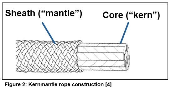
Kernmantle ropes are used for high-stress applications, rescue, and climbing due to their unique construction, elasticity, resistance to wear, and high tensile strength [4]. Their superior properties can be attributed to the synthetic fibers (mostly nylon and/or polyester) that are braided into two elements: an interior load-bearing core (kern) and a protective and smooth outer sheath (mantle) [4, 5].
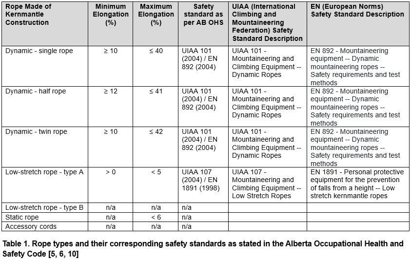
The Cordage Institute defines three types of kernmantle ropes: dynamic, low-stretch, and static based on their elastic properties [5]. These three types of kernmantle ropes are manufactured to meet different specifications depending on the end user. Regardless of the specific life safety application, the use of kernmantle ropes are subject to compliance with workplace safety regulations. For example, Alberta’s Occupational Health and Safety (OHS) code requires that ropes are approved to manufacturing safety standards as listed in Table 1 below [6].
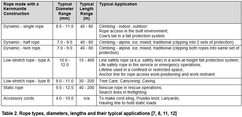
- Dynamic ropes have high energy absorption capacity to absorb the energy of falls by elongating resulting in a lower impact force (i.e. softer catch) on the climber. Dynamic ropes are classified into single, half, and twin ropes based on rope diameter and safety ratings [7]. Each of the three types of dynamic ropes is designed for a specific climbing application.
- Low-stretch ropes have a high tensile strength and low elongation, which tend to have higher impact forces on the climber. They are typically used in rope-supported work at height, caving, rappelling and rescue operations [7].
- Static ropes also have a high tensile strength and little to no elongation under load, without any dynamic energy absorption capacity. They are typically used in a rigging or rope rescue system for lowering and hauling applications [8, 9].
As shown in Table 2, various kernmantle rope types, along with their typical characteristics, are tailored to their specific applications for use in both recreational and industrial settings.
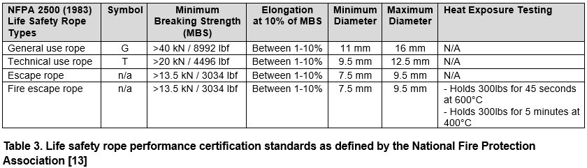
When kernmantle ropes are used as a life safety rope “solely for the purpose of supporting people during rescue, firefighting, or training evolutions,” they are subject to meeting the minimum requirements published in the National Fire Protection Association (NFPA) standards as documented in Table 3 below [14].
Given a wide variety of kernmantle ropes are available on the market, the selection of a rope is specific to its application that meets the industry’s rope safety performance certification as summarized above [6, 10, 13].
Following the conclusion of all the informational interviews I had conducted with 13 rope experts, I documented a summary of the users requirements by industry in Table 4, which ultimately formed the basis of my innovative design for iRiS.
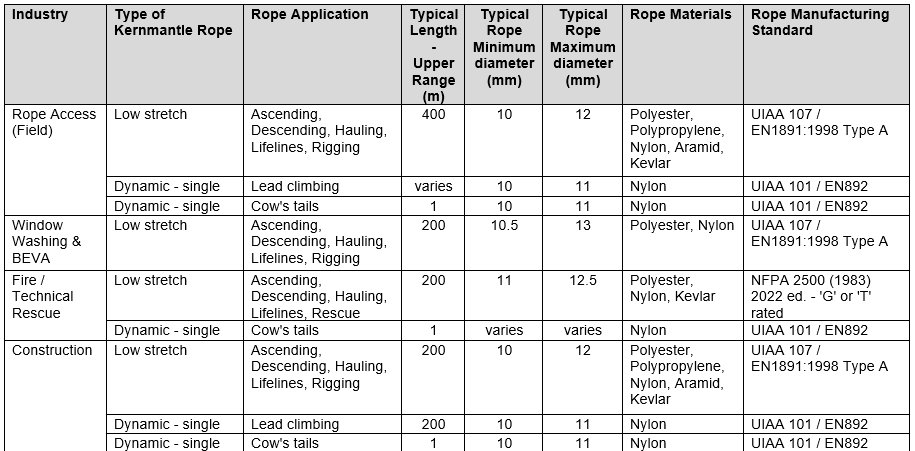
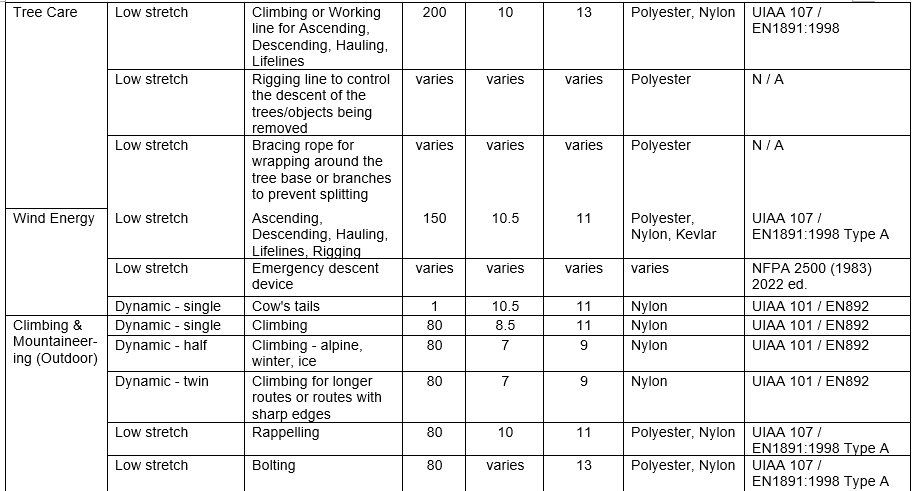
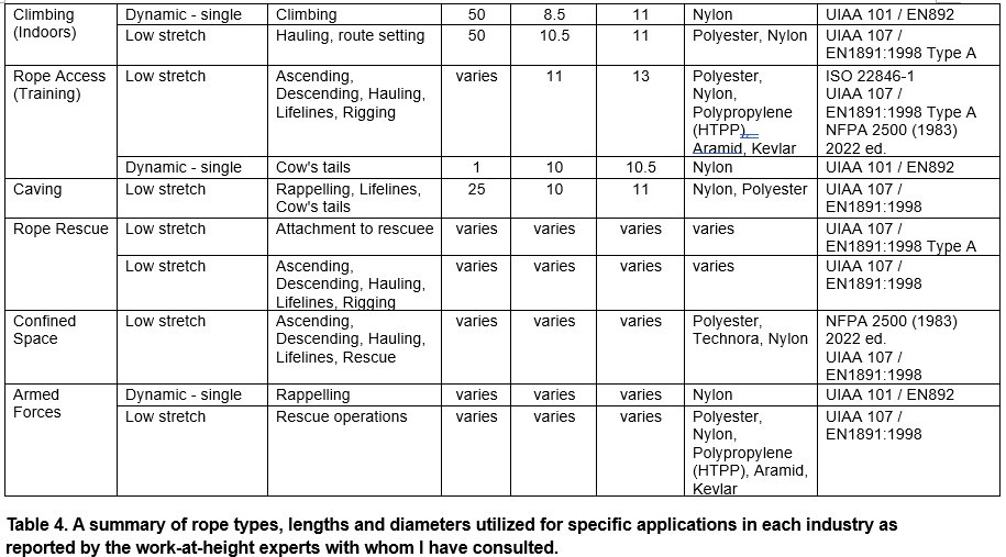
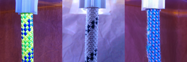
As shown in Table 4, the vast majority of kernmantle ropes used today fall in the range of 7.5mm to 12.5mm in diameter. While there are still a few rope models on the market that are thicker than 13mm in diameter, the rope experts I interviewed said that they were either in the process of phasing them out in replacement for thinner and lighter ropes, or already did not use them. As a result, I made a design decision to have iRiS inspect ropes with diameters between 7.5 and 12.5mm. Three rope samples that fall within this diameter range for iRiS are shown in Figure 3 below.

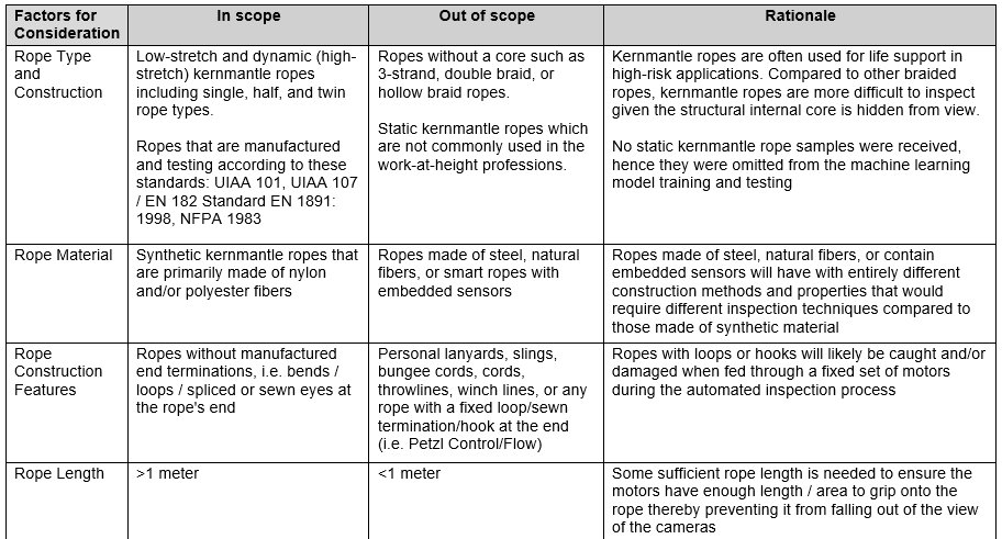
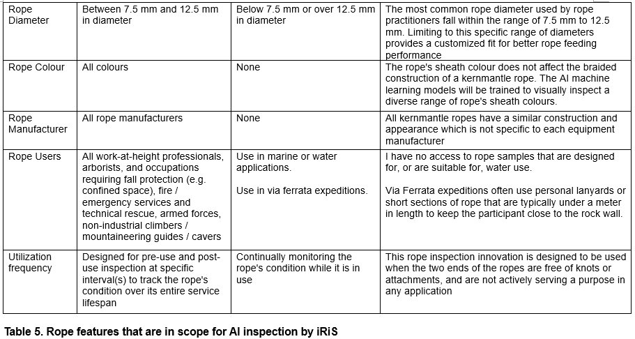
In addition to the important design criteria on what diameter range of ropes can be fed into iRiS for AI inspection, Table 5 defines the scope of all other rope features, along with their rationale, that can be inspected by iRiS.
B. Kernmantle Rope Inspection
Brand new kernmantle ropes are manufactured to very strict international standards as listed in the tables above. However, every use puts wear on the rope’s structure and thus kernmantle ropes are constantly being inspected. Currently, kernmantle ropes are inspected via a visual and tactile process which is typically conducted simultaneously by hand in a smooth repetitive motion as shown in Figure 4 below [15].

These manual inspections typically occur at the start or end of the work shift/day. In addition, more detailed and thoroughly documented inspections are conducted at regular intervals, such as monthly or semi-annually depending on whether the rope is being put up, taken down, or has recently become dynamically loaded (such as catching a fall). This process ensures damages are found, reported, and repaired or replaced before it is next used. These requirements for manual inspection are outlined in workplace safety regulations, and often explicitly documented in industry-specific safety guidelines [6, 16, 17].
Overview of the manual rope inspection process
Ropes are first checked to make sure they have their identification labels, are not older than their maximum manufacturer-specified service life (typically 10 years), and are the same length as indicated by their respective labels [15]. Once all this fundamental information is checked, the visual and tactile inspection process may begin.
Visual
During the visual portion of an inspection, an inspector will visually scan the outer sheath of the entire length of the rope for any imperfections including but not limited to cuts, fuzziness, and burns. If any damages or areas needing more attention are found, as shown in Figure 5 below, the inspector will either decide to remove the damaged area (such as cutting off the damaged section of the rope) or retire and replace the entire rope.
This visual inspection process would be replicated by iRiS where a three-camera system is used to create a 360 degree view of the rope’s outer surface. The three camera streams are run through an AI machine learning model that has been trained to recognize a wide variety of damage as itemized in Figure 5, and report it back to the user who can then decide what actions to take next.

Tactile
The tactile inspection is an extremely important component of the kernmantle rope inspection process, as damage to the core is often hidden behind the sheath, making it easy to miss during the visual inspection.
During the tactile inspection process as illustrated in Figure 4, an inspector runs their hands along the entire length of the rope feeling for abnormalities (such as soft spots, swelling, and changes in shape) primarily in the internal core but also in the sheath [15]. They employ the use of techniques such as bending the rope and comparing its compressibility to other sections in order to assess the location and severity of damage as shown in Figure 6 [18].

In order to replicate the tactile sensing of our own human hands, iRiS is designed to utilize a variety of sensors in addition to current inspection techniques. For example, to test for soft spots in the structure of the rope, I decided to use a compressibility metric (how easily the rope can be compressed when pinched) measured by a simple load cell and spring configuration, rather than knotability (the ability to bend and put knots in the rope). This is because each rope has its own unique handling characteristics with some ropes being much more easily bent than others. Additionally, iRiS is designed to utilize a modified tire depth gauge to measure and report the diameter of the rope as it passes through the system. Such measurements can be used to compare to its original manufactured dimensions in order to detect any change(s) in the rope’s shape over time. This is helpful since many devices (used for belaying, ascending, and abseiling) used in climbing and rope access today can only accept ropes of a specific diameter range. Once a rope’s shape changes from circular to oval, it often no longer fits within the desired diameter range and thereby rendering it unusable with these devices.
C. Computer vision using Convolutional Neural Network Architecture
Computer vision is a field of AI where its core task is enabling computers to see, understand, and classify images [19]. Modern computer vision has been driven forward by the machine learning architecture commonly known as Convolutional Neural Networks (CNNs). CNNs were developed from the study of the brain’s visual cortex since the 1980s and have become especially popular in image recognition applications [20]. Convolutional Neural Networks are typically known for their ability to perform well in complex visual perception tasks such as self-driving cars and medical imaging, making them an excellent fit for a rope inspection application as in iRiS.
The superior performance of CNNs was boosted by the three converging forces that are also in play for the design of iRiS:
- Data - A custom dataset of rope images created from taking original photographs of a combined total of 73 retired and new ropes with a total length of 540 meters
- Computing power - Equipped with a powerful, purpose-built edge computing device (Nvidia Jetson Orin Nano Super) that is designed to run inference with complex models
- Machine learning architecture - Uses EfficientNetB5, a high-performing CNN architecture designed to balance computing power demands with machine learning model performance [20]
For iRiS to provide real-time damage detection, the “eyes” of this computer vision system require a full 360 degree field of view to inspect the entire surface of a rope. As such, three high-frame rate cameras were built into the design, along with a LED light strip to provide consistent background lighting for iRiS to meet the portability design objective for use in all work settings. One downside with camera-based computer vision models is that their performance is often limited by the camera image quality. Accurate pixel-by-pixel representation is essential for providing precise information (in the form of pixels) to the machine learning model for training and prediction. This is why iRiS was designed to use high-resolution, global shutter cameras which eliminate the effect of motion blur seen by cameras that use an alternative rolling shutter technology [21].
Method
Ideation Phase
While the users’ requirements were being collected at the start of the Ideation phase of the Design Thinking framework, I continued to explore and refine the conceptual design of iRiS. The investigation of available technology options/systems and their compatibility were conducted in three main areas:
- The mechanical system – automates the movement of the entire length of the rope (once it is fed into iRiS by a user) by guiding and transporting it through iRiS. This allows for both visual inspection (namely the “eyes” for computer vision processing) and tactile measurements to be taken before the rope is pushed back out the enclosure. Some of the key enabling components include (a) enclosure for the entire system; (b) power supply; (c) motors, motor shields; and (d) rope guidance system
- Computing hardware – includes all the processors and interfaces which enable real-time inspection data collection, data processing power and connectivity with AI models for data reporting to users, such as (a) cameras, lighting, USB interface; (b) GPU-accelerated computers (Graphics Processing Units), AI application software development kits; (c) microcomputer board, Ethernet cable; (d) touchscreen, (e) a load cell, a digital caliper, and a time-of-flight (ToF) distance sensor; and (f) adjustable power supplies
- AI machine learning algorithms and data – high-performing machine learning architecture to enable real-time computer vision predictions with (a) Convolutional Neural Network (CNNs); and (b) dataset preparation specific to kernmantle ropes
Prototype Phase
Modular Design and Development
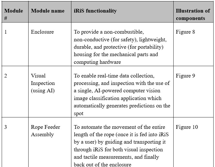
For the development of iRiS, I adopted a modular design approach to build the iRiS prototype in parallel. An overview of the modules is provided in Table 6 below.
Prior to purchasing any component in store or online, I first compiled a list of components by module (which can be found in the concatenated log book) and then drew a simplified pictorial electrical diagram (see Figure 7 below) to show their connectivity and check for completeness.


The development steps described below were not performed in chronological order unlike the detailed steps that had been documented in the concatenated log book. Only the major steps in prototyping each module were provided as an overview.
Module 1: Enclosure
I purchased two plastic enclosure bins from a local store and began to take measurements to markup a potential layout for the placement of components as well as holes that would need to be drilled. Next, I mounted the cameras to the enclosure bins using screws of various sizes as well as a few 3D printed mounts. During the image collection stage, modifications were made to the interior walls of the lower bin to provide a translucent background behind the cameras which creates more consistent lighting conditions. Last but not least, a power strip was installed to the upper enclosure bin, which supplies power to all the computing hardware.
Module 2: Visual Inspection System
3D Modelling of the Mechanical System of iRiS
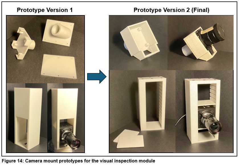
Given the design incorporates 3 global shutter cameras (2 CSI cameras & 1 USB), I had to create two types of the camera mounts (see Figure 14 below). However, a second (final) version of each type of camera mount was created for its own reason. The CSI camera mount found at the top of Figure 14 was redesigned to better distribute the load of the heavy camera in order to improve the durability of the part over time. On the other hand, the USB camera mount found at the bottom of Figure 14 was redesigned after I realized the camera had to be turned 90 degrees to display the vertical image in a 480-pixel by 640-pixel format.
Cameras and Lighting Setup
Immediately after the cameras were mounted into the enclosure using my custom 3D printed camera mounts, I tested the cameras individually and adjusted their lenses to focus on the rope right in front of them and determined that in their mounted positions they had an approximate field of view of 8cm high. I then installed a bright LED light strip to guarantee that there would be enough illumination to see the surface of the rope regardless of the setting or time of day iRiS would be used. Next, I created a python script to run the three camera streams and allow me to take pictures of each rope, section by section, with each of the three cameras. Last but not least, I coded a final GStreamer pipeline script which would allow me to stream my camera feed directly to my Jetson computer which would be actively running the machine learning model application.
Machine Learning Model and Development
To enable a real-time rope inspection application using AI, a binary image classification model would be trained via supervised learning to predict whether damages are detected on a frame-by-frame basis within each individual camera stream. Each image used for training, validation, or testing the model was classified by me to be either “Good” (meaning the rope section in frame is not showing any visual sign of damage) or “Bad” (meaning the rope section in frame is showing some visual signs of damage such as those listed in Figure 5b).
Collection and Preparation of Machine Learning Data
I prepared and sorted all 76 donated ropes into 4 categories: 17 brand new ropes, 33 retired ropes in as-is condition, 22 retired ropes that are in as-is retired condition but also had sections of the rope added with lab-simulated damages, and 4 retired ropes that only had lab-simulated damages. Lab-simulated damages were created outdoors using rocks, bricks, and a box cutter to create and/or intensify damages such as abrasion, cuts, and frays on some rope sections.
Out of the 76 ropes, 6 retired ropes, with a total length of 176.5 meters, had been set aside as “unseen” ropes to simulate “real-world” testing of the machine learning model post-deployment.
I took 6517 original photographs of the 70 ropes mentioned above with a split of 3236 in the “Good” classification (for rope sections with no detected damages) and 3281 in the “Bad” classification (for rope sections with a varying degree of damages similar to those shown in Figure 5a). I then performed data cleansing to remove images that were not an accurate representation of its class, resulting in a final balanced dataset of 6394 original images (3169 "Good" plus 3225 "Bad") in total.
All images in the dataset were then resized to a consistent resolution of 456 by 456 pixels using Microsoft PowerToys such that input shape (the image pixel resolution) would match that of the square image resolution typically used when training models with a CNN architecture, potentially leading to greater training accuracy.
The full dataset of original photographs was then split using Google Colab, with an allocation of 60% for training (3836 original images), 20% for validation (1279 original images), and 20% for testing (1279 original images).
Data Augmentation
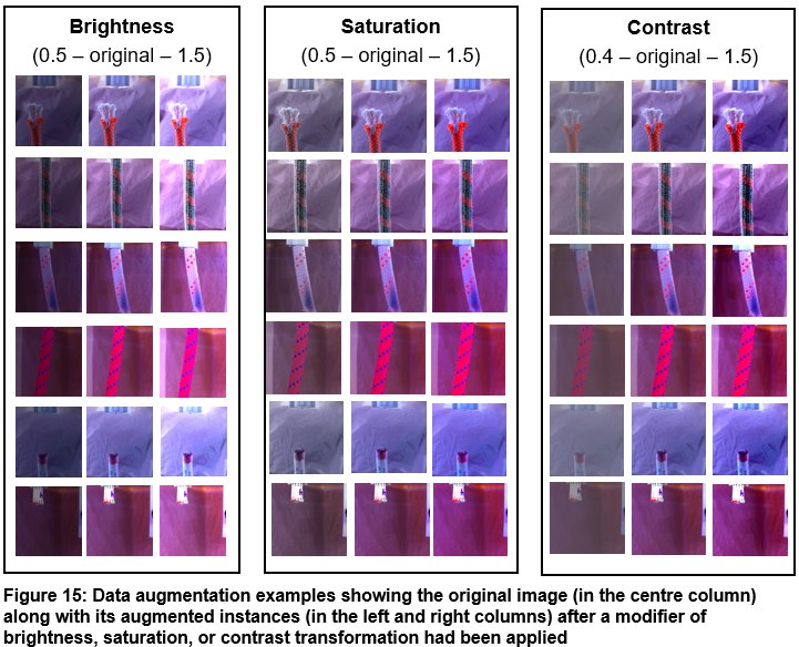
Once my original images were split into their respective folders for training, validation, and testing, I ran an experiment to test the different types of image augmentations available in the PyTorch ‘color_jitter’ library. The experimental trials began with individually testing each type of image augmentation technique focusing on the visual quality (namely brightness, saturation, contrast, and hue) to determine a desirable modifier value range that would generate augmented images that depict realistic lighting conditions in both indoor and outdoor settings. After running multiple trials, I settled on a target range for each augmentation type and then applied a combination of augmentations using random values within this acceptable modifier range.
The augmentation used a combination of brightness, saturation, and contrast transformations to artificially increase the number of images in my training dataset from the original 3836 images to a total of 7672 combined original and augmented images (examples shown in Figure 15 below). One benefit of increasing the size of the training dataset is to reduce overfitting as a regularization method to control model complexity, provided that the augmented training instances are realistic [20]. In other words, the model would be more tolerant to different lighting conditions to meet the portability design objective of iRiS.
Machine Learning Model Training, Validation and Testing
To develop the machine learning model used in iRiS, I opted to use the EfficientNetB5 Convolutional Neural Network architecture as its input shape (the image resolution trained on) was 456 pixels by 456 pixels. This 456 by 456 pixel resolution closely matched the 480 pixels by 640 pixels resolution of the original images that I took, which implied that I only had to crop a little bit from the top and bottom of each image when resizing the images to create the full dataset for training.
To train my custom model, I used a machine learning training technique called transfer learning. In transfer learning, one would reuse a pretrained model (such as EfficientNet) and leverage its pretrained features in order to quickly and very accurately train a model that is dedicated to a specific AI model application. In addition to feeding my own training data into the model, I periodically unfroze the last 3 of 8 “blocks” in the EfficientNetB5 architecture every 5 epochs during training, which allowed the model to retrain the weights in the last few layers of the architecture during the finer tuning stages of the model training process. This was completed out of a Google Colab notebook (to utilize their Nvidia T4 graphics cards) and I used PyTorch to build and train each of the models using different hyperparameters. Additionally, Adam was selected as the optimizer over Stochastic Gradient Descent (SGD) for its simplicity and that online tutorials on the use of Adam were readily available. Overall, I found that in addition to unfreezing blocks, the combination of (a) training on a batch size of 32 coupled with an initial learning rate of 0.001, and (b) decreasing the learning rate by a factor of 10 after every 5 epochs, resulted in the highest accuracy and lowest loss. It was observed that the model performance peaked at around the 20th epoch of training.
For each of the 14 models I trained, I used the Sci-kit learn metrics library to generate a classification report as well as a confusion matrix to visualize the performance of each model when evaluated on the testing dataset. A full log of these performance metrics (document titled “Machine Learning Model Tuning Log”) has been provided in the Attachment section below.
Module 3: Rope Feeder Assembly
Once a rope is placed into iRiS, the rope feeder assembly guides and pulls the rope through and back out the system allowing for both a visual inspection and tactile measurement to be taken. This capability is driven by two systems, the motor and motor shield drivers as well as the 3D printed rope guidance components.
Rope Guidance System Prototype Iterations
As shown in Figure 16, ropes travel through iRiS in a C-shaped pathway. This shape allows iRiS to visually inspect ropes while they are travelling vertically down the funnel rather than horizontally, which allows for the provision of an uninterrupted 360 degree view of the ropes.
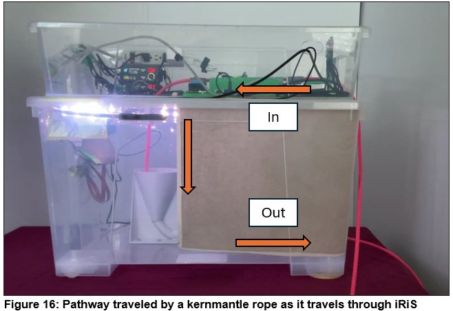
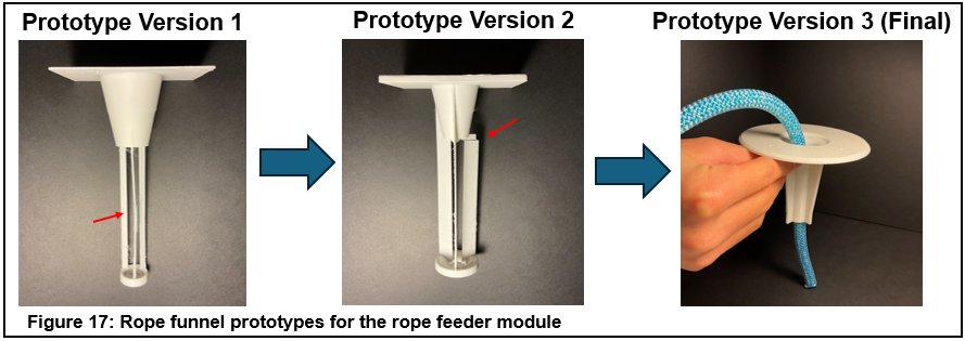
Unfortunately, the geometry of this C-shaped pathway can also be problematic as it creates friction (also known as rope drag) since the rope is forced to contact and bend around more surfaces. As a result, I designed my 3D printed components to guide the rope through this complex shape while creating the least amount of friction possible. For example, when designing the initial rope funnel guide piece, I attempted multiple designs which all snapped at the layer lines shown at the top of Figure 17. Following these unsuccessful attempts, I took inspiration from a standard kitchen funnel and redesigned the CAD model creating a final prototype (version 3 as shown at the top right of Figure 17) that was incredibly strong and it accurately guided the rope into the bottom funnel-shaped feeder each time.
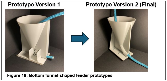
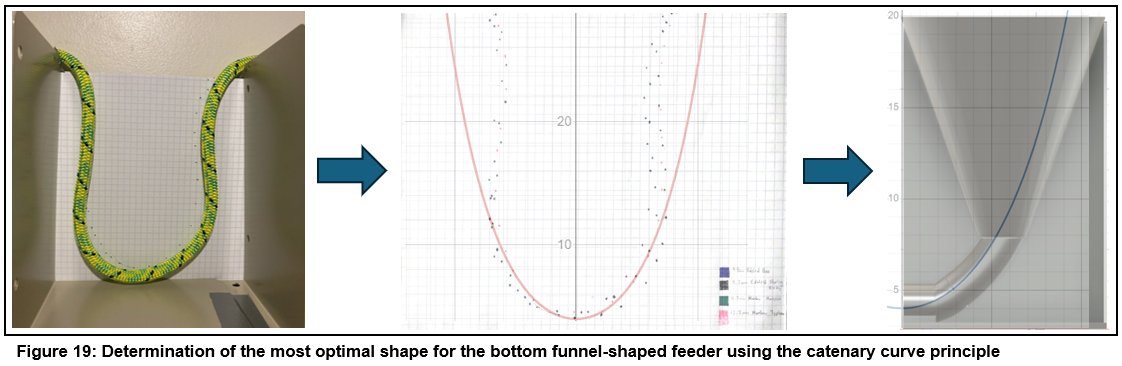
Another rope guidance component that underwent two iterations was the bottom funnel-shaped feeder. In order to reduce the surface friction observed on the side walls of the funnel-shaped feeder in the first prototype (shown in Figure 18), I ran a test based on the principle of catenary curves in which I hung ropes of many different diameters from the same two points as shown in Figure 19. Following the ropes paths, I then plotted points on a piece of graph paper and then overlaid it with various graphs of catenary curves that had different coefficients to find the coefficient of the catenary curve that best matched the shape of the ropes.
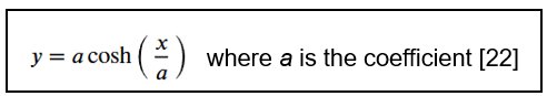
Once I had determined the coefficient of best fit was 4 where the ropes followed the arc that was generated by the formula of y = 4cosh(x/4), I was then able to create a CAD model of the bottom funnel-shaped feeder with this exact shape and subsequently 3D printed out the final (version 2) prototype as shown in Figure 18.
Motors and Motor Shields
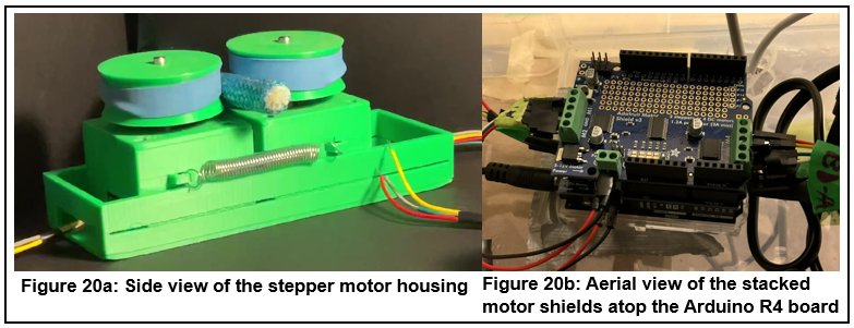
Four NEMA 17 stepper motors were connected via jumper ribbon cables to the two Adafruit motor shields, which control the speed of the rope that is pulled through iRiS. Each pair of the stepper motor was first placed into a 3D-printed housing and then topped with feeder wheels (wrapped with rubber bands to provide grip). A pair of springs were installed in the exterior of this housing to provide a compressive force that grips onto the rope and pulls it forward (a side view of the motor housing is shown in Figure 20a). Each motor was fed 12-volts of power by the motor shields which were stacked onto the headers pins of the Arduino R4 Wi-Fi board (as illustrated in Figure 20b) thereby allowing the motor system to be controlled wirelessly.
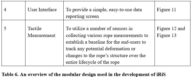
Module 4: User Interface
To control iRiS I fastened a responsive 7-inch LCD touchscreen to the top of the enclosure and connected it to the Jetson Orin Nano Super using a DisplayPort to HDMI cable. I then enabled an onscreen keyboard in the Jetson’s settings to allow iRiS to be controlled without the use of a mouse or keyboard.
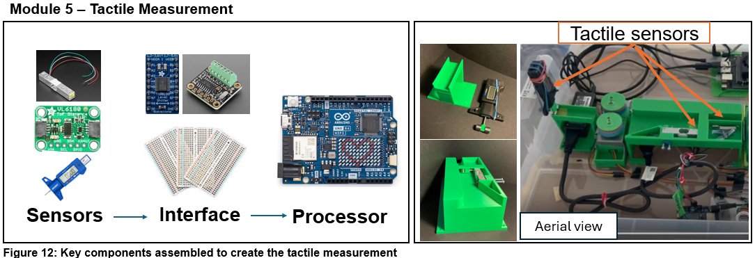
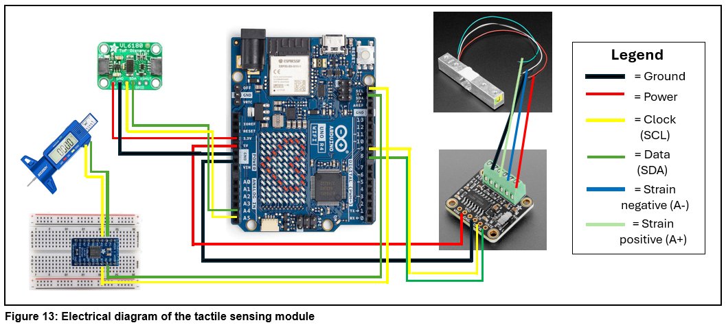
Module 5: Tactile Measurement
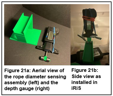
To retrieve data from the tactile sensors, I soldered the header pins onto the time-of-flight distance sensor, Adafruit motor shields, HX711 load cell board, and the level-shifter. Next, I designed and 3D printed the housing unit for the load cell and time-of-flight sensor which would also ensure the rope would be properly guided first horizontally and then vertically down (as in the C-shaped pathway shown in Figure 16 above) towards the rope funnel. In addition, I designed and 3D printed the rope diameter sensing assembly and installed the digital depth gauge caliper (as shown in Figure 21 below). Finally, I wired all the tactile sensors up to an Arduino, screwed down the 3D printed housing unit and the rope diameter sensing assembly, and then created both a Bluetooth version and non-Bluetooth version of an Arduino script that would read the data off each of the sensors in real time.
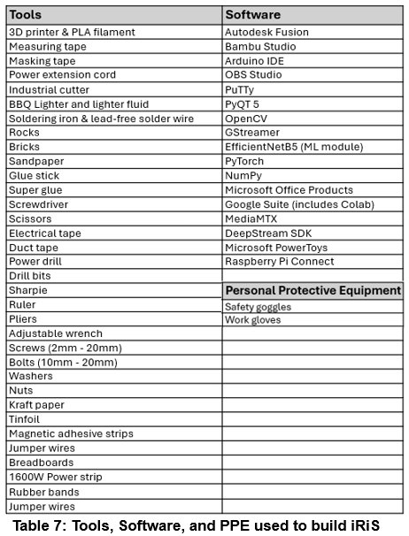
Materials and Tools
All the materials that had to be purchased specifically for this project were itemized in the Components List documented in the concatenated log book. Existing household tools and safety equipment, 3D printing hardware and computer software that I had used during the development and prototyping of iRiS are listed in Table 7 Below.
Analysis
iRiS Functionality Testing
Visual Inspection
While assessing the performance of the visual inspection module over multiple rope inspection cycles, I observed that the cameras could smoothly and consistently keep up at a rate of 10 frames per second without appearing to be dropping frames. Based on this observation, I calculated that with a field of view of 8cm and an overlap between frames of 4cm, the visual inspection system could theoretically inspect the rope at a rate of 0.4m/s, allowing a standard gym climbing rope that is 40m in length to be inspected in 100 seconds. This speed would likely be on par if not faster than the amount of time it would take a recreational climber to inspect their own rope. As such, this suggested that should the power and speed of the motors be upgraded without any budget constraints, the visual inspection module of iRiS, in its current state, would have the capability to inspect ropes at comparative speeds to humans. When coupled with the fact that the iRiS system could run non-stop for a few hours without encountering any operational or performance issues, the visual inspection module proved to be robust and consistent.
Machine Learning Model Performance
To test the accuracy of the deployed machine learning model, I used six retired ropes, with a total length of 176.5 meters, in their original state of use in an indoor setting (with no simulated damages added). These ropes were previously set aside for this purpose of ‘real-world’ deployment testing given these “unseen” ropes were not used in the development or validation of the machine learning model. Before testing the model on these “unseen” samples, I first identified and documented the ground truth prior to running the test which included 60 (20 x 3 camera frames) instances of “Good” samples and 60 (20 x 3 camera frames) instances of “Bad” samples per rope based on my own observation and judgement. I then tested the model on each section of the rope and simultaneously jotted down whether the model predicted the same as, or differently from, what I considered to be the ground truth.
Overall, the same machine learning model that scored a 95% accuracy when tested on the testing dataset, received a 90.2% accuracy when deployed on 6 real-world, unseen, retired rope samples in as-is condition (with no induced damages). A comparison of the model performance observed during testing vs. post-deployment is shown in Figure 22 below.

Tactile Measurements
All the tactile sensors were tested individually with specific test cases as described below. First of all, the time-of-flight distance sensor reported accurate readings when I tested it by placing my hand at various depths away from the sensor.
To test the depth gauge, I took 10 different data points along a rope sample making sure to place both the good and the bad sections of 5 ropes under the probe to compare the resulting data values. I found that the digital caliper was approximately 1 to 2 mm off from the ropes’ manufactured specified diameter but could still sense a change in diameter for the sections of the rope that were significantly thinner.
To test the load cell, I increased the delay between readings to 10 seconds and once again took 10 different data points along 5 distinct rope samples. I found that it was a bit difficult to determine whether damage was present just by looking at the load cell data and comparing it to data from other sections of the rope in only one measurement instance. Without any historical data measurements on these ropes, there was no baseline to identify potential changes over time. However, I was able to determine that a sudden value decrease of 80,000 or more between data points was usually an indication of rope damage.
iRiS End-to-End Integration Testing
Device Portability
To test the portability of iRiS in its ability to operate in an outdoor setting, I ran a rope inspection cycle in the backyard of my home to see if the whole system would work at a temperature of zero degrees. Upon heading outside, I plugged iRiS into the exterior wall outlet using an extension cable and turned on the device. The Jetson Orin Nano and the Raspberry Pi both booted up and the touchscreen turned on and worked as expected. I started an inspection cycle and saw that the motors began turning and all the other components appeared to work well. The predictions made by the machine learning model in this integration test cycle appeared to be accurate, and the camera streams ran well without any issues. All of these observations and results confirmed that iRiS performed as intended even in the outdoors.
The Speed of rope feed through iRiS
To test the speed at which iRiS can inspect a rope, I decided to run ropes of different diameters (8.2mm, 9.8mm, 12.2mm) through the motors 3 times, resulting in a total of 9 trials, and measured the length of rope pulled through in a 100 second time frame. Once the trials were completed, I averaged out the lengths and then calculated the average speed in centimetres per second (cm/s). iRiS pulled the 9.8mm rope through the fastest at a speed of 4.1cm/s, this was closely followed by the 8.2mm ropes which traveled at a speed of 4.0cm/s. The feeder motors really struggled to pull the 12.2mm rope through, likely due to the extra weight and compressive pressure needed, and as a result it pulled the entire 12.2mm rope through at an average speed of 3.1m/s.
Conclusion
Project Objectives Met
The intelligent Rope inspection System (iRiS) prototype has been validated to function as a portable, user-friendly system equipped with AI capabilities that offers real-time, automated and robust kernmantle rope inspection. Rope users who climb and/or work in vertical environments can simply feed their kernmantle ropes into this innovative system, and they will be provided with data on visual damages detected on the rope’s surface and tactile measurements that could be used as a baseline for tracking deformations or changes to the rope’s shape and/or state of the inner core over the rope’s entire service lifespan.
Potential Applications of iRiS to enhance Workplace Safety
The use of AI-powered iRiS does not conflict with rope inspection or workplace safety regulations that are in place today. Instead, the use of iRiS can be integrated into existing work processes throughout a rope’s lifecycle where its future deployment includes at least these two user scenarios:
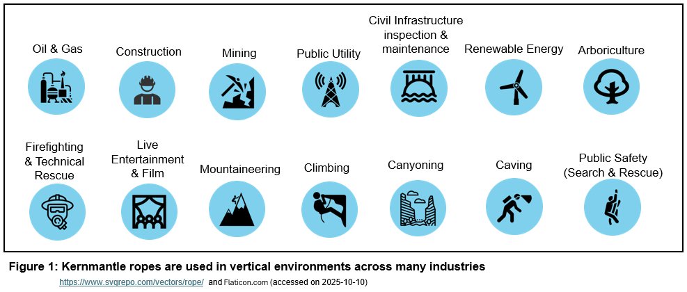
- iRiS can be used as a demonstration tool during the hands-on training of new rope users on how to manually inspect a rope. A broad user population will benefit from the use of iRiS in training sessions including (a) new or inexperienced lead climbers; (b) workers requiring fall protection training and/or safety orientation in any of the industries that operate out of a vertical environment (Figure 1); (c) new rope access technicians; and (d) rope practitioners requiring advanced training in technical rescue operations.
- iRiS can be utilized to perform a pre-use or post-use check in conjunction with manual checks. iRiS could also be used to perform the more detailed and thoroughly documented inspections that are required at regular intervals, such as monthly or semi-annually depending on the rope manufacturer’s specifications and/or specific application requirements. One of the benefits of using iRiS in a formal inspection is its ability to report a set of quantitative data for longer-term traceability of the rope’s condition over its entire service lifecycle.
Future Work
I consider this early version of iRiS an evergreen working prototype where continuous improvements and iterations can be made to broaden its usability for specific industrial and non-industrial applications. Industries that are experiencing significant growth, such as the global wind industry, are seeing a rising need in training new rope practitioners, and can greatly benefit from adopting iRiS as a training tool [23].
Some of the future modifications to iRiS I am considering include:
- Expanding the data reporting functionality to provide the ability to export data into a spreadsheet to improve the efficiency of rope inventory management as well as rope maintenance scheduling and record keeping;
- Offering physical tagging of the section(s) of rope where damages are detected during an automated rope inspection cycle so the user needs not be physically and continuously monitoring the user interface screen to be informed of damaged rope sections;
- Adding a reliable, high-capacity battery pack to supply power for the entire iRiS system to be used in remote areas such as on mountains and in caves;
- Upgrading the power of the motors to increase the speed of the rope being fed through iRiS; and
- Providing the flexibility to integrate RFID (Radio Frequency Identification) and NFC (Near-Field Communication) tagging capability to speed up the data entry of rope information into the iRiS system.
Citations
- DiMartino, T. J., & Sandwith, C. J. (2009). Proper care, maintenance, and inspection of climbing ropes to reduce degradation and help determine when to retire them. OCEANS 2009, Biloxi, MS, USA, 2009, pp. 1-8. https://doi.org/10.23919/oceans.2009.5422306
- Interaction Design Foundation. (2016). What is Design Thinking? The Interaction Design Foundation - IxDF. https://www.interaction-design.org/literature/topics/design-thinking
- IRATA International. (2025). What Is Rope Access? IRATA International. https://irata.org/page/what-is-rope-access
- Maxim Climbing Ropes. (n.d.). Rope Info - Maxim Climbing Ropes. Teufelberger Fiber Rope Corporation. Retrieved October 23, 2025, from https://www.maximropes.com/rope-infos/
- Cordage Institute. (2025). Terminology for Fiber Rope. Cordage Institute. https://ropecord.com/terminology/
- Government of Alberta. (2025). Occupational Health and Safety Code Province of Alberta. https://search-ohs-laws.alberta.ca/legislation/occupational-health-and-safety-code/
- The British Mountaineering Council. (2024). Ropes: a guide for climbers and mountaineers. The British Mountaineering Council. https://www.thebmc.co.uk/en/ropes-a-guide-for-climbers-and-mountaineers
- Edelrid. (2025). Ropes Save Lives. Edelrid. https://edelrid.com/us-en/professional/ropes
- International Technical Rescue Association. (2025). Rope Rescue Terms & Definitions. ITRA. https://www.technicalrescue.org/wp-content/uploads/2025/05/RR-Terms-and-Definitions-May-13-2025.pdf
- UIAA. (2025). Safety Standards. UIAA. https://www.theuiaa.org/safety/safety-standards/
- IRATA International. (2014). ICOP latest versions: Part titles and publication dates. IRATA International. https://irata.org/downloads/2055
- Arborist Supply Co. (2025). Arborist Supply Co. Inc. https://www.arboristsupply.ca/
- CMC Pro. (2013). NFPA 1983 - Life Safety Rope Performance Requirements. CMC. https://www.cmcpro.com/nfpa-1983-life-safety-performance-requirements/
- National Fire Protection Association (NFPA). (2024, May 31). NFPA Glossary of Terms (2024). Nfpa.org. https://www.nfpa.org/downloadable-resources/definitions/nfpa-glossary-of-terms
- Edelrid. (2020\, September 10). PPE inspection - how do I check my climbing rope? | EDELRID. Edelrid.com. https://edelrid.com/us-en/knowledge/knowledge-base/ppe-inspection-how-do-i-check-my-climbing-rope
- WorkSafeBC. (n.d.). Occupational Health and Safety Regulation. WorkSafeBC. Retrieved September 26, 2025, from https://www.worksafebc.com/en/law-policy/occupational-health-safety/searchable-ohs-regulation/ohs-regulation
- Energy Safety Canada. (n.d.). Standards & Programs. Energysafetycanada.com. Retrieved December 2, 2025, from https://www.energysafetycanada.com/Standards
- Petzl. (n.d.). Inspection procedure. Petzl.com. Retrieved August 20, 2025, from https://m.petzl.com/sfc/servlet.shepherd/version/download/068Tx00000ITdN0IAL
- Serrano, L. G. (2021). Grokking Machine Learning. Manning.
- Geron, A. (2022). Hands-on machine learning with Scikit-Learn, Keras, and TensorFlow, 3rd Edition. O’reilly Media, Inc.
- Raspberry Pi Ltd. (2023, March 1). Buy a Raspberry Pi Global Shutter Camera – Raspberry Pi. Raspberry Pi Ltd. https://www.raspberrypi.com/products/raspberry-pi-global-shutter-camera/
- LearnPlaySolve. (2020, October 4). The Catenary: A Vector Calculus Problem. [Video]. YouTube. https://www.youtube.com/watch?v=-xYUxxDDP6E
- Global Wind Organisation, & Global Wind Energy Council. (2024, November 14). Global Wind Workforce Outlook 2024 - 2028. Global Wind Organisation. https://www.globalwindsafety.org/statistics/global-wind-workforce-outlook-2024---2028

Acknowledgement
I would like to thank the following rope experts who generously shared with me their real-world experiences and insights.
- Mr. Chris Aziz (Structure Group Ltd.),
- Ms. Lenora Barnes and Ms. Annie Hewitt (Canmore Cave Tours),
- Mr. Adam Gaulin (Rope-A-Dope Windows Inc.),
- Mr. Steve Hands (MCL Height Safety),
- Mr. Joel Hawkins and Mr. Kyle Egeland (True Mettle Rope Access Centre),
- Mr. Clayton Holt (APEX Rope Industries Inc.),
- Mr. Henk Klei (Braids and Laces Limited),
- Mr. Joel Miller and Mr. Damien Sovd (Calgary Fire Department Windsor Park Emergency Response, Station 11),
- Mr. Jeff Perron (SassoVertical)
- Mr. Brent Peters (PeakSTRATAGEM),
- Ms. Nikki Romeril and Mr. Rob Romeril (Arborist Supply Co. Inc.),
- Mr. Dries van Hecke (Kiewit Corporation),
- Mr. Simon Villeneuve (Calgary Climbing Centre),
- Mr. Jeremiah Wangsgard (Petzl)
- Mr. Phil Westenberger (Edelrid)
Special thanks to the following organizations for their donations of retired and/or new ropes that were used to train and test the machine learning model:
- APEX Rope Industries
- Arborist Supply Co. Inc.
- Calgary Climbing Centre
- Canmore Cave Tours
- MCL Height Safety
- True Mettle Rope Access Centre
I am also grateful to my school’s Science Fair teacher sponsor, Ms. Trainor, for facilitating this opportunity to participate.
Finally, I would like to thank my parents and sister for their encouragement and support.