Advancing Brain-Computer Interface Technology through Innovative Design for Enhanced Human-Machine Interaction
Daniil Tyurin
Grade 10
Presentation
Problem
The creation of Brain-Computer Interfaces (BCIs) represents a groundbreaking frontier in the convergence of neuroscience, technology, and medicine, with a profound impact on healthcare [1], [2], [3]. BCIs offer transformative solutions for curing blindness by directly stimulating the visual cortex and restoring mobility to paraplegics through the interpretation of neural signals. These interfaces also advance brain disease treatment and research by providing real-time insights into neurological disorders and facilitating targeted therapies. Beyond clinical applications, BCIs serve as powerful tools for general neuroscience research, offering unprecedented opportunities to study cognitive processes and enhance cognitive abilities through neurofeedback. The integration of BCIs into medical practice also holds the promise of eliminating or significantly mitigating the limitations imposed by neurological conditions, ushering in a future where healthcare is revolutionized by the seamless integration of the human brain with cutting-edge technology. But despite the transformative potential of BCIs, their current adoption faces challenges rooted in the size, invasiveness, and lack of spatial resolution of existing devices [3]. Additionally, concerns about infection and malfunction further impede accessibility. The technology's decoding capabilities remain limited, affecting the precision of neural signal interpretation. Addressing these challenges, including the need for advanced computational power, is critical for optimizing BCIs and for their widespread acceptance.
Current state of the art BCI technologies exhibit limited capabilities in one or more of several ways, size, damage to the surrounding neural tissue, longevity, capability, safety, and ease of implantation [3]. Microwire based brain computer interfaces are prone to issues such as buckling, limited recording capabilities, damage of the surrounding tissue, and a relatively low longevity [3], [4]. Flexible film sensors are incapable of accurate or large scale detection, localized implants create challenges such as heat distribution and potential damage to the neural tissue, and intravascular means create background noise, hindering the decoding capabilities of the technology. It is for these reasons and more a different approach to the creation of BCIs is proposed. Several hundred microscale neural implants that relay with an external decoder would minimize damage, increase longevity almost indefinitely, increase precision within recording, and create ease within the implantation system itself. The design and creation of such a system of micro scale neural implants is the basis for this project, and if successful, would bridge the gap in accessibility, safety, and capability of BCI technology.
Method
Abstract
This scientific paper introduces an approach to neural activity detection utilizing micro-scale piezoelectric crystals, wherein backscatter ultrasound waves are generated through an external device, and the crystal, deformed by neural tissue voltage, sends back distinct waves indicative of the applied voltage. My proposed methodology involves implanting micro-scale piezoelectric crystals near neural tissue. As neurons generate electrical impulses, the corresponding mechanical vibrations from the piezoelectric crystals induces backscatter ultrasound waves when an external device sends ultrasound signals to the crystal. The paper emphasizes the high sensitivity, spatial resolution, and temporal precision of the proposed approach, surpassing current invasive techniques. The paper also details the creation of piezoelectric crystals with multiple tentacles, each having different electrical resistances. This innovative design enhances spatial detection capabilities, allowing for the differentiation of neural signals based on the unique electrical resistance profiles of the crystal's tentacles.
1.2.Broad Review
Although BCI’s are not a new concept, and their design and implementation dates back to as early as 2010, their safety and capabilities have been severely lacking, especially in comparison with the advancement of other technologies and sciences that further our understanding of things such as material sciences and neurobiology. And as such, with recent advancements within neuroscience, and materials sciences, a new approach to the detection of not only neural activity within the brain, but also within other regions of the nervous system must be presented, which is the purpose of this project. But before even considering the possibility of designing a new system and approach to this problem, previous approaches, systems, materials, and results must first be understood, which is the purpose of this broad literature review, as to solve a problem, the problem must first be understood.
As previously explained, this paper outlines and demonstrates the engineering process in the design, development, and testing of a system of microscale piezoelectric material based crystals, and external sensor devices for the detection of neural activity in not only the brain, but other areas of the nervous system as well. This was proposed as the primary focus of this research based on several factors, including previous background knowledge of several ideas within BCI’s, material science, and neurobiology, and, more specifically microscale piezoelectric materials and ultrasound backscatter, because of the growing necessity for the individual to be more interconnected with the digital world around them, safely, quickly, and reliably. The biggest “selling points”, so to speak, of this project are the predicted safety in both the implantation, and long term use of microscale piezoelectric crystals within biological tissue. While their size, if successfully and functionally properly created, would most certainly distinguish them in safety over other, current state of the art BCI systems, it would also allow for higher density of detection sites in similarly sized areas of neural tissues.
To analyze and explain why it would be beneficial for this system to remain on the microscale, and use ultrasound, in conjunction with piezoelectric crystals, instead of other wireless means of communication, and other material choices that may at first seem simpler, let us first discuss current state of the art BCI’s and their shortcomings.
BCI’s are generally split into two major categories, invasive, and non invasive. Although other categorizations of BCI’s exist, such as chemical sensing, electrically sensing, and so on, let us first look at the primary differences between invasive and non invasive. Invasive BCI systems are just that, an invasive system that breaches the confines of skin and bone to get a higher detailed, more in depth analysis of the brain activity within a certain area. Non-invasive systems on the other hand are systems that generally remain outside of the body, or systems that enter the body through familiar, and previously well repeated means, such as intravascularly. Oftentimes, the preferred methodology for patients, and for individuals who are necessitated by outside circumstance to receive a BCI, is the non-invasive system, due to both its relatively low risk, and its capability to be removed at almost any time if complications were to arise. Invasive BCI’s on the other hand, are the preferred methodology for more accurate, and higher resolution patterns, due to the nature of the applied signals. The sensor is not only closer to the signal that it initially needs to monitor and detect, but it is also more precisely placed in the landscape of the biological tissue, be it that of the brain, or that of other nerves or parts of the nervous system. Most state of the art, or groundbreaking technologies within BCI’s today are invasive in nature, due to several factors, but the primary leading one being that material science and knowledge of scientific principles has not yet caught up with the requirement of accurate detection of tiny electrical impulses deep within tissue, and behind a barrier of bone. Although safer systems for invasive BCI’s are being developed, and it is often those systems that are referred to as groundbreaking, their limiting factors in the nature of the detection, and the accuracy of detection hinders them from being used in neurobiological research when it is often times necessary to detect small activations, rather then detect large areas of simultaneous activation. This is a primary driving factor in the development of micro piezoelectric crystals for neural detection, as on such a small scale, the crystals have the ability to detect activation of only a couple neurons, rather than large chunks of neurons for the cataloging of the activity. Their small size would also make them safer and less invasive then the current system, allowing for unparalleled research into the neural activity of the brain.
Furthermore, the other greatest theoretical benefit for the use of micro scale piezoelectric crystals within the detection of neural activity, is the ability for the crystals to provide a higher resolution image of activation, compared to other methodologies. If the detection of neural activity is thought of as a three dimensional map of the brain, we can with most current state of the art technologies, detect activation on a single planar site, without very much variation of depth within the detection, because the probes cannot be stacked on top of one another, and cannot be placed in high density. Micro scale detection sites, on the other hand, provide the ability to be placed incredibly densely within the brain, but also on top of one another, depth wise. The ultrasound backscatter wave, should also theoretically be much different for each layer of depth, at least in the sense that if it is at least detectable at different intervals, due to the distance, and the speed of travel within the medium, it should be possible to differentiate between the crystals at different depths.
1.3.Biological Background
As this project is an engineering project in nature, with certain elements of physics involved, its primary purpose is still biological, and by that, I mean that the projects main purpose is to advance biological, and mainly, neurobiological sciences by advancing the systems that test and catalog the information of neural tissues, and the brain. As this is the case, and if we consider this project as the design of the tools that measure and analyze biological processes and tissues, then it becomes easier to understand why biological background is required before even the initial design of the project. To create a tool to measure and analyze a phenomenon, primarily the interactions between neurons, and other neural cells, we must first understand the phenomenon thoroughly. With this brief introduction, let us first analyze our primary target, the brain.
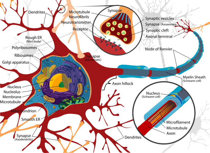
The brain is an incredibly complex biological structure within us that regulates our thoughts, our feelings, and our background processes that keep us alive. In its entirety, it is still not fully understood, and may never be fully understood, due to its sheer complexity, and perplexing nature. While we understand approximately what each area of the brain is responsible for, and how, as well as why it functions, we cannot with full certainty be sure of, basically anything about it. The brain, while primarily made up of roughly 60% fat, the other, 40%, is full of functional, and incredibly important neural cells. Further, the brain is divided into large subsections, such as the prefrontal cortex, in accordance with their function, and while these areas are important to understand for the purposes of placement of the microcrystal detection sites, they are not of importance in the understanding of the cellular makeup of the brain, which is the primary interest when creating a device for the measurement of that activity. For our cells of interest are the neurons, and while the brain is composed primarily of two divisions of cells, glial, and neural, neural cells, or neurons are our cell of interest for their primary function. Glial cells provide structure to the brain, and act as assistants to the function of the neurons, and while they do serve an important purpose within the overall function of the brain, neural cells are responsible for thought, and as such, are the cells important in the design of the tools to measure them, to further our understanding of the brain, but to also allow for heightened human-machine interaction. Neurons are an electrically excitable cell that fire electrical signals called action potentials across a neural network, and they communicate with other cells via synapses, which are specialized connections that use amounts of chemical neurotransmitters to pass the electrical signal from the presynaptic neuron to the target cell through the synaptic gap. And, although it is true the process within a neuron the transmits information is not entirely electrical, it is still the primary driving factor behind the passing along of information inside of a neural network, and while systems for the chemical detection of transmission between neurons is in development, and to some extent do exist, this project will focus entirely on the electrical potential and the electrical discharge of a neuron for the detection of its activation. Neurons, are cellular structures just like any other, meaning that they consist primarily out of the same components as any other animal cell, such as the cell membrane, nucleus, and all the other organelles that comprise the primary structure of a cell responsible for many things, such as the maintenance of energy within that cell, although, as a specialized cell neurons do exhibit slightly different structures than ordinary cells. For our purposes, major organelles within the neuron will be excluded from our analysis, due to the fact that they are unnecessary for the understanding of the overall function of the neural cell, in terms of outside electrical activation and stimulation. While they are responsible for these happenings, they are ultimately unimportant and the detection of the activation of a neuron, and we will therefore assume some amount of background knowledge within the organelles of cells and their primary functions. With that being said, let us first analyze a typical neural cell, or rather one of the most common types of neural cells. Neurons are highly specialized for the processing, and the transmission of signals within a neural network, and given their said diversity of function, there exists a wide variety within shape, structure, and positioning within neural cells, and as such the following description of a neural cell is one that is very generalized, and might not apply to every single type of functional neuron. Firstly, within a neuron there exists the soma, and it acts as the primary body of the neuron, it contains the functional organelles of the cell and can range anywhere from five to one-hundred some micrometers in diameter. The soma of the neuron is also intrinsically connected to the detection of activation within a neuron, as it is connected to the cell membrane on which the action potential of the neuron occurs, but this is discussed later Nextly within the overall structure of a neural cell, there exist dendrites, and they are the extensions of the neural cell, similar to branches of a tree, and they are the primary source of input of the neural cell, and for our purposes of the detection of neural activity, will be the primary areas of implantation of the micro crystal, besides of course the axon of the neuron, for the detection of neural activity in surrounding neurons, as communication and activation of a neuron is a two-way process requiring first the initial activated neuron, and secondly the receiving neuron. Finally, there exists the axon, which is a long, fine, cable-like protrusion of the neural cell that has the capability to extend hundreds, if not thousands, or tens of thousands of times the diameter of the soma in its length, and its primary purpose is to carry nerve signals away from the soma. Most types of neurons only have one primary axon, but this axon often branches extensively, enabling the singular length of the axon to communicate with several target cells. The connection between the soma of the neuron and the axon is called the axon hillock, and is oftentimes the most easily electrically excitable part of the neuron, due to its high concentration of sodium channels, which we will discuss in depth later. The furthest part of the axon away from the soma is called the axon terminal, and it contains the synapses of the neuron which allow the communication of the neural cell with other neurons via the use of neurotransmitting chemicals. A basic structure of the neuron can be seen below in figure 1.3.1.
While all of the aforementioned aspects of the neural cell are important to understand within the grand scheme of the neuron, our primary focus is the neuron's ability to transmit signals between cells. This occurrence is due to the neuron producing an electrical action potential along the cell membrane, which as a signal is transmitted and conveyed to other cells via chemical means. Neuron action potentials are a fairly complicated process, and they are the process most valuable to us in the detection of neural activity using a system which relies on electricity for detection, but the process essentially breaks down into five stages. First, before explaining the process of the action potential in depth, it is important to understand the fact that a neuron's membrane, at rest, has a potential, or an electrical charge difference across the cell membrane of the neuron when they are not actively transmitting a signal. At rest, the inside of the neural cell has a negative charge relative to the outside, at around -70mV. This resting potential is maintained by the selective permeability of the cell membrane to different ions, primarily sodium, potassium, and chloride. During the firing of the neuron, and the activation of the process of the firing of the action potential, the neuron firstly experiences depolarization. Depolarization it the neurons ability to temporarily change the membrane potential by selectively opening certain ion channels allowing positive ions, typically of sodium, to flow into the neural cell, and as more sodium ions enter the neuron, it becomes less negative, leaving its resting potential state, and allowing it to transition to the next stage of the action potential process when the depolarization of the neuron reaches a critical maximal threshold of approximately -55mV. Once this critical action potential threshold is reached, voltage-gated sodium channels in the membrane of the neural cell open, causing a sudden influx of positively charged sodium ions into the cell, which causes a sudden, and sharp reversal of the cells membrane potential, forcing the inside of the cell to become more positive than the outside, which is the action potential of the neuron. After reaching the peak of the cells action potential, which can range anywhere from 40mV - 70mV, the membrane potential begins to repolarize to its original resting state, as voltage-gated potassium channels open, potassium ions flow out of the neuron, creating an outward movement of positive charge from the inside of the neuron, restoring the inside of the neuron closer to its original negative state, leading to the fall of the neurons action potential. After this, in some cases, exists the force of hyperpolarization, which is the direct result of the repolarization state of the neuron, in which the membrane of the cell becomes more negative than the resting potential, which is caused due to the over prolonged opening of the potassium channels, or the over prolonged closing of the sodium channels. Following either the period of hyperpolarization, or the more adequate repolarization of the membrane from the action potential of the neuron, comes the refractory period, which is a period of time after the firing of a neuron in which it is incapable of producing another action potential. This period ensures that the action potential travels in one direction along the neuron, and is also a period for the repolarization of the neuron from the hyperpolarization state of the neuron. A graphical representation of the firing of a neuron's action potential can be seen below in figure 1.3.2.
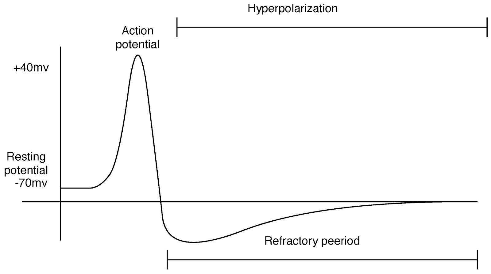
The above graph demonstrates the resting potential of the neuron, and the sudden spike of the neuron's activity, before the climb of its action potential. The y axis is representative of the millivolts of difference within the neuron's membrane, and the x axis is representative of some arbitrary time. The tight side of the graph displays the period of hyperpolarization of the neural membrane, and the neuron's slow flow of positive ions to regulate its overly negative potential, to a more natural resting potential for the cell. The propagation of the action potential, starting with the body of the neuron, and traveling down the axon to transmit a signal is exactly what we are trying to monitor with electrically sensitive monitoring equipment. The propagating action potential through the axon is the indicator of cellular activation, and is exactly the easiest area to detect this electrical activation in. While chemical methodologies for the detection of the activation of the neuron are incredibly interesting for several reasons, their placement would be slightly different, and their measurements would also be slightly different. Now, with a slightly better understanding of the electrical activation of the neural cell, which has not been mentioned yet, but is several orders weaker than the 50mV - 100mV of action potential difference within the membrane of the cell, as it is not directly monitoring the travel of ions through the membrane, and is not directly placed within the membrane. The actual measured signal is much weaker, and is solely from the induced electric field from the action potential, and changes within the membrane potential, we can now begin to understand what we need from the designed system, and how it needs to be achieved.
1.4.The Physics of the Reverse Piezoelectric Effect
Piezoelectricity is the foundational principle behind the basis of this project, and can be summarized as the accumulation of electric charge on the surface of a material resulting from the deformation of the crystal lattice structure of the material. Since it is the materials capability to generate an electric charge on the surface of the material from the materials crystal lattice structure being deformed due to outside stress, the effect relies on the asymmetry within the crystal lattice structure of the material to produce the charge. The word piezoelectricity itself means electricity resulting from pressure, and is derived from ancient Greek. The effect is the result of the electromechanical interaction between the mechanical and electrical states in a material which exhibits no inversion symmetry, which is the symmetry within the crystal lattice structure of the material. The effect is closely related to the occurrence of electric dipole moments within a set material, and the asymmetry of the crystal lattice structure of the material.The non-centrosymmetric crystal structure, and the distribution of positive and negative charges within within a set unit cell being asymmetrical produces a shift in the charge density of the material when an external mechanical force is applied to the material, and therefore the crystal lattice structure. The mechanical deformation, and the resulting shift of positive and negative charges along the planes of the materials crystal lattice structure, creates displacement regions of the charges, resulting in an electric dipole across the material. The cumulative effect of the electric dipoles across the materials crystal lattice structure, leads the material to the generation of an overall electric polarization, which manifests as an electric field within the material, creating potential difference across the materials surface, creating a voltage potential difference. Figure 1.4.1 demonstrates an example of the type of asymmetry within the charge distribution of the material required for the production of the piezoelectric effect.
The creation of the slight difference within the overall electric charge of the crystal lattice structure on the atomic scale, produces an overall voltage across the materials surface on the macro scale. This is of course dependent on the structural formation of the crystal lattice structure within the material, and the deformation of the crystal on the macro scale. While the piezoelectric effect is responsible for the creation of the transducer device, and several technologies responsible for the production of ultrasound waves, our true understanding needs to be within the inverse piezoelectric effect, or the reverse piezoelectric effect. The reverse piezoelectric effect is the effect responsible for the deformation of an asymmetrical crystal lattice structure under the introduction of an external electrical potential across the surface of the material. This effect is the primary effect behind the basis of this project, and is the foundation on which the methodology of detection of neural activity is built, as under the applied voltage across the crystal from an action potential from a neuron, the crystal will deform, producing a different backscatter wave. The reverse piezoelectric effect is connected closely to the piezoelectric effect, and is the direct result from the asymmetrical charge distribution within the crystal lattice structure of the material. As the inverse of the piezoelectric effect, oscillation of the electrical potential across the material creates an oscillating mechanical deformation within the crystal, creating a wave of sound, and if tuned correctly, ultrasound. This creates an interesting opportunity within the creation of the micro crystals, as the design can both rely on ultrasound backscatter, but also creation of an original ultrasound wave. The effect of piezoelectricity is also important to understand to properly balance the required voltage across a certain size of crystal to create noticeable deformation, with the amount of deformation required for its detection within backscatter, and the equations for which are vast, and incredibly complex. The equations responsible for the prediction of the factors and results of the piezoelectric effect rely on several factors, including the crystal lattice geometry, the voltages, pressures, and overall material properties. Typically, you would first start by describing the constituent properties of the material through the equations that describe the strain, the electric field, and the piezoelectric coefficient, but since this data has previously been discovered and recorded, for the development of piezoelectric requiring technologies, this data, when required for the testing and production of the micro crystal, will be used from these sources. After the basic properties of the material are laid out, we can estimate the strain produced by the piezoelectric effect, but again, this information is already well established, and as such, will simply be used from reputable scientific publications when the time for production and testing occurs. The most important thing to note, the takeaway so to speak, behind the physics of the reverse piezoelectric effect, is that the deformation is miniscule. The unit in which piezoelectricity, and subsequently the inverse piezoelectricity is measured in, is picometers per volt, in the case of a material in the thickness of millimeters. While backscatter can detect this, it becomes an issue when talking about whether it is feasible of a system that is confined to the human body to detect this size of a deformation. This coefficient of piezoelectric deformation of course changes with the size of the crystal, and therefore the amount of energy required to shift the crystal lattice structure of the system, and on the micro scale, the deformation, even in picometers, becomes much more noticeable. And this value further changes because of the size difference, as the energy required to shift the crystal in the same order of picometer deformation becomes less, from a singular volt, so some amount of millivolts, depending on several factors. This understanding of the piezoelectric effect, and the subsequent inverse piezoelectric effect become incredibly beneficial in the design of the crystal structure of the system for several reasons. We can roughly, without conducting any sort of mathematical testing, estimate the crystal deformation of some set crystal under some set voltage, and vice versa, allowing us to create a system that can properly react, or modify, and then react, to the minute signal produced from the action potential of a firing neuron. We can also experiment with different, slightly more hypothetical methods for the detection of activation, such as non-backscatter based systems, that rely entirely on the implanted system to produce an initial ultrasound wave.
1.5.Knowledge Gap and Purpose
The knowledge gap of existing, and already well grounded research, and the necessary questions within this project are very closely interlinked, as there is no reason for asking a question, and conducting experimental analysis within this project to answer it, if it was already something well established, and known. The gap, within the overall scope of the project, that the project aims to fill, is whether a deformation within a piezoelectric crystal can be advantageously used for the detection of neural activity, and if so, what is the most optimal geometry, and set up, as well as creation of the micro sized piezoelectric crystal? The purpose of the project is well outlined, and has several far reaching implications in several fields, the primary of which, and what the project is focused on are medicine, and neurobiology. A system with the appropriate parameters that have previously been outlined, if produced, and if functional, has the potential to expand, and propel our understanding of the functions, functionality, and the overarching complexity within such a large structure as the brain. Not only this, but when applied to less research focused, and research dependent fields, such as commercial and medical use, paralysis, vision, and locked in syndrome all have the potential to be cured. The system, while showing great commercial and medical use potential, if successful, can also be applied to several other sectors of development, such as micro and nano fabrication, ultrasound technologies, and ultrasound and acoustic microscopy.
2.Methods
Now, with a complete understanding of the biological sciences, relating to this project, as well as the properties of piezoelectric materials, we can start to consider the design, development, and testing of the system. This includes, but is not limited to, the production and testing of the micro crystal system, the potential implantation methodologies, the production and testing of the transducer device, and coding of the system for potential medical use. This section outlines aspects of the system such as material considerations, design considerations and designs of the crystal system, as well as the transducer system, the design of the testing set up, and the production of each of these aspects of the project. It also outlines the procedure for testing within the system.
2.2.Research Questions
The purpose of this research, and the primary question asked when setting out to conduct this project, was, is it possible to create a minimally invasive system for the detection of neural activity within the human body? When further examined the question itself could be broken up into subsections that analyze and question the safety, reliability, production, and actual detection of activity on a reliable scale. Through not only broad literature review, but also preexisting background knowledge on the topic, the question and primary goal of this research was shifted, from a generalized perspective on the analysis of possibility of such a system, to the creation of a system that relies on the reverse piezoelectric effect, the subsequently created deformation and the resultant patterns of ultrasound backscatter. The question from this point on, narrowed down from the initial purpose of the creation of a minimally invasive and maximally safe device for the detection of neural activity, to the creation and testing of such a system based on the reverse piezoelectric effect and ultrasound backscatter, becomes, is it possible to create a system reliant on these properties, and if so, how? The question, broken down for simplicity and for the quick understanding of the purpose of this research is broken down in figure 2.2.1 below.
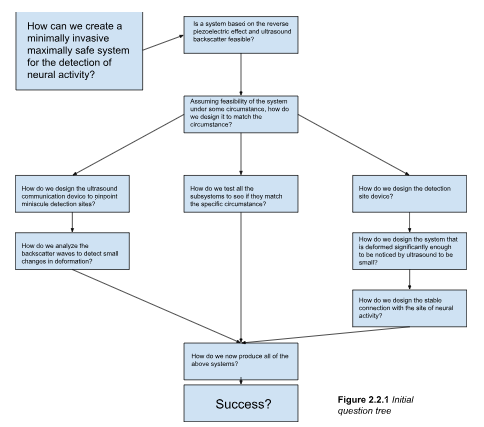
The above figure demonstrates a logical progression of questions asked in the development of such a system, and as such is the basis of questions asked, and questions answered in this paper. By splitting the design into first the theoretical, then the developmental stages, the creation of the final product is simplified. It is also important to note that this project is written as both a logical progression of events, especially in the design and production phases, but also as a straightforward recollection and description in the necessary areas, such as the abstract and conclusion sections of the project. Since the project follows a more engineering-like approach to the design of the system, some amount of creative leniency is allowed within the design and description of the design, such as reworks based on foreseen difficulties, or changes to the project that are dependant on results which would have otherwise not been mentioned in that area of the project.
2.3.Initial Design
In the domain of BCI’s, the pursuit of improved spatial resolution, reduced size, and enhanced data collection efficiency prompts the exploration of innovative design approaches. The primary goal is to achieve unprecedented spatial resolution by integrating piezoelectric microscale crystals into the BCI architecture, aiming to surpass limitations related to the bulkiness of conventional BCIs and spatial precision constraints. To reduce the size and intrusiveness of the BCI, the utilization of microscale materials is proposed for seamless integration into neural tissues. This reduction in physical footprint enhances patient comfort and safety, and allows for more precise placement within the neural environment. While the general concept for the use of microscale materials is proposed, the engineering requirements for this system must include, at a minimum, the accurate detection of activation and the precise measurement of the location of activation relative to other implants. The overarching goal is to ensure the system is safe, minimally invasive, and maximizes resolution. The proposal of microscale piezoelectric crystals over other means of detection is one well grounded in previous research.
Free floating implants maximize efficiency of data collection over a broad area of neural tissue, but challenges arise from the transmission of data between the free floating implant and an external decoding device in terms of safety and size of the device itself. Microwires are limited to small areas of neural tissue, and issues such as buckling and displacement arise from the substantially different Young's modulus of the microwire and soft neural tissue. Other instances and methodologies for the detection systems of BCIs can be examined, and all have considerable drawbacks in one or more of several aspects. Microscale implants remain one of the only solutions that balances the issues with current state of the art BCIs, and are feasible. For these reasons, the constraint that the detection device must be at a microscale is placed on the design and development of the device. The goal in creating a device of such a small scale is to allow for maximum safety by effectively bypassing abrasion damage due to differences within Young's modulus of the device and the neural tissue. It is also set out within the goals that the system is capable within an acceptable degree of accuracy to detect and transmit the presence of neural activity. The system must also be maximally safe, and must remain non toxic, as the major driving reason for the development of a microscale BCI is improved safety, in combination with improved spatial resolution, due to the fact that more detection sites can be placed in one area due to their size.
A microscale implant, due to the limitations of current technologies, cannot instantly detect and transmit a signal from its implanted location, potentially several centimeters within tissue, to an external device. Therefore, to enhance the capability of the system while keeping it within the parameters of the microscale, it is important that the actual microscale implant acts as the detection site, and a partner device, most likely located on the outside of the tissue, acts as the receiver of data from the microscale implant. To establish a wireless connection between the two devices, radio waves and other high energy waves, due to the potential for the tissue to absorb excess energy and heat up, are excluded. Ultrasound remains the only feasible method of wireless communication between the detection site and the partner device, without complicating the detection site device, as a microscale piezoelectric crystal can be used. Piezoelectric crystals have been the main methodology for the creation of ultrasound devices, and deform when introduced to an amount of voltage. This deformation is measurable by external ultrasound waves in a process known as backscatter, in which the deformation of the crystal causes a different, and measurable backscatter wave, and is the basis for the entire project. The piezoelectric crystal has the potential to be made small enough to fit within the microscale parameters (20-100 micrometers) of the device while still exhibiting the reverse piezoelectric effect, powered solely by the voltage difference within neural tissue. To minimize size of the detection site device, backscatter can be employed by the partner device to return a different wave depending on the deformation within the micro crystal, which itself is dependent on the voltage imparted on the device. The micro crystal itself must be designed small enough to be safely implanted within neural tissue, and must have a simple enough geometry to be produced via current nanofabrication techniques, while still exhibiting a complex enough geometry that the backscatter is noticeable and distinct. While on the other hand the transducer device must be made small, and effective enough to be placed, primarily, beneath the skull, without negative interaction with the brain matter. Both devices must also be safe enough to be implanted into neural tissues, without causing severe abrasion damage, and without causing long term poisoning from the degradation of the chemical constituents of the devices.
2.4.Material Considerations And Specific Design
With the initial idea described, we can now begin to consider the specific designs of both the implanted microcrystal detection site, and the transducer device, the former of which will be discussed in much more depth than the latter, for the sole purpose of centralizing, and focusing on one area of research within the project, to not only conserve energy, time, and resources. With that being said it is important to understand that the crystal itself, will not be designed and made as a traditional, and simple crystal structure, but is instead, when referencing the crystal, is referencing the complete micro scale detection site, which must be composed out of several different components. All of these components play a vital role within the overall functionality of the crystal system as a whole, and each one must be dealt with carefully. Although there are several subsystems of the crystal structure, it can primarily be broken down into two, the tendrils, or the connective leads between the crystal and the surrounding neurons, to allow for extended range and not just the immediate surface of the piezoelectric crystal, and the piezoelectric crystal itself, responsible for the communication of neural activation, through its own personal deformation, detected by the ultrasound wave produced by the transducer. First, as one of the most crucial aspects of the project, it is important to consider the properties of the piezoelectric crystal itself, as it is responsible for communicating the activation of neurons in its vicinity to the external transducer device. It must be considered for several properties, the primary of which, in the current state of development, is the level of energy required to deform the crystal, and the ease at which the crystal is deformed. It is of course, in the long run important to also consider the toxicity of the chosen material, and the ease at which it can be produced into some chosen geometry, but these will affect our consideration much less than the actual order of deformation of the crystal. The below table is a compilation of all of these factors of some randomly selected materials, all chosen for some part of ease within at least one section of the required fields.
|
Name |
Reactivity and Toxicity |
Order and Strength of Piezoelectric Deformation |
Production Methodologies |
Other Considerations and Overview |
|
Lithium tantalate (LiTaO3) |
Generally safe. Lithium compounds may become toxic if exposure becomes increasingly excess. No adverse reactions can be identified on the biological level if the material is properly encapsulated. If not, complications arise. |
Lithium tantalate exhibits strong piezoelectric properties. For exact value calculations refer to the following mathematical formulas. |
This material, under very specific conditions, can be grown like an ordinary crystal. Under constant agitation from an outside source inside a bath of solution, the crystals can grow, and from there, can manually be chosen for the most optimal conditions. Adjusting flow rate, and agitation amount will also be beneficial to the crystal growth. “Powdering”, is another method for the production of the crystals specifically, which is the process of taking larger crystal pieces and working them down to a smaller size, and hand picking the desired crystals under microscope. While more labour intensive, it may be the only option when techniques involving nanosecond lasers are not available. |
Lithium tantalate is widely used in acoustic optic devices, and other such devices where frequency control due to piezoelectric responses is necessary, due to the materials powerful piezoelectric response. Overall due to the materials general safety, and strong order of piezoelectric deformation, it remains a highly ranked potential candidate for the production of the finished microcrystal. |
|
Lithium niobate (LiNb03) |
Generally safe. Lithium compounds may become toxic if exposure becomes increasingly excess. No adverse reactions can be identified on the biological level if the material is properly encapsulated. If not, complications arise. |
Lithium niobate exhibits strong piezoelectric properties. For exact value calculations refer to the following mathematical formulas. |
This material, under very specific conditions, can be grown like an ordinary crystal. Under constant agitation from an outside source inside a bath of solution, the crystals can grow, and from there, can manually be chosen for the most optimal conditions. Adjusting flow rate, and agitation amount will also be beneficial to the crystal growth. “Powdering”, is another method for the production of the crystals specifically, which is the process of taking larger crystal pieces and working them down to a smaller size, and hand picking the desired crystals under microscope. While more labour intensive, it may be the only option when techniques involving nanosecond lasers are not available. |
Lithium niobate due to the high piezoelectric coefficient is often used in acoustic wave devices, Telecommunications, and modulators. For similar reasons as lithium tantalate, lithium niobate remains a strong competitor for the final production of the micro crystals, due to its general safety and strong piezoelectric effect response. |
|
Langasite (La3Ga3SiO14) |
Generally safe. Compounds may become dangerous in high quantities of exposure without proper encapsulation. |
Langasite exhibits moderate piezoelectric properties. For exact value calculations refer to the following mathematical formulas. |
This material, under very specific conditions, can be grown like an ordinary crystal. Under constant agitation from an outside source inside a bath of solution, the crystals can grow, and from there, can manually be chosen for the most optimal conditions. Adjusting flow rate, and agitation amount will also be beneficial to the crystal growth. “Powdering”, is another method for the production of the crystals specifically, which is the process of taking larger crystal pieces and working them down to a smaller size, and hand picking the desired crystals under microscope. While more labour intensive, it may be the only option when techniques involving nanosecond lasers are not available. |
Due to langecites moderate exhibition of the piezoelectric effect, it is often used for weak surface acoustic wave devices. Overall, while an interesting consideration for the final production of the microcrystal, due to its low piezoelectric coefficient, it will most likely not be selected for initial testing. |
|
Lead titanate (PbTiO3) |
Extremely toxic. Lead compounds are incredibly hazardous, and incredibly dangerous situations may arise from the implantation of lead crystals within neural tissue. Adverse reactions can be avoided on the biological level if the material is properly encapsulated. Otherwise complications arise. |
Lead titanate exhibits strong piezoelectric properties, and any material consisting of lead, primarily, will exhibit incredibly strong piezoelectric properties, with the weak voltage of activation within the material crystal. |
This material, under very specific conditions, can be grown like an ordinary crystal. Under constant agitation from an outside source inside a bath of solution, the crystals can grow, and from there, can manually be chosen for the most optimal conditions. Adjusting flow rate, and agitation amount will also be beneficial to the crystal growth. “Powdering”, is another method for the production of the crystals specifically, which is the process of taking larger crystal pieces and working them down to a smaller size, and hand picking the desired crystals under microscope. While more labour intensive, it may be the only option when techniques involving nanosecond lasers are not available. |
While an unsafe option due to the toxic nature of lead, Lead titanate is an incredibly strong material in terms of the piezoelectric properties within it. And while it is important to mention the safety aspect of the finished product, for our purposes it is incredibly important to consider the strength of the piezoelectric effect within the material, and the activation voltage of the material. It is also important to note that while lead remains an unsafe choice, it is one of the strongest competitors in terms of functionality. |
|
Quartz (SiO4) |
Safe. Quartz crystals are not toxic, and major complications only arise from the inhalation of fine quartz crystal dust. |
Quartz exhibits weak piezoelectric properties, but properties that are nonetheless potentially useful. |
This material, under very specific conditions, can be grown like an ordinary crystal. Under constant agitation from an outside source inside a bath of solution, the crystals can grow, and from there, can manually be chosen for the most optimal conditions. Adjusting flow rate, and agitation amount will also be beneficial to the crystal growth. “Powdering”, is another method for the production of the crystals specifically, which is the process of taking larger crystal pieces and working them down to a smaller size, and hand picking the desired crystals under microscope. While more labour intensive, it may be the only option when techniques involving nanosecond lasers are not available. |
While quartz does demonstrate the piezoelectric effect within its crystal structure; its weak nature may push it out of the running for the finished micro crystal production. This might be changed later on, if safety becomes a higher priority than functionality, due to quarts being non-toxic in nature, and its simplicity within production. |
|
Sodium bismuth titanate (NaBi(TiO3)2) |
Generally safe. Compounds may become affected by biological reactions if not properly encapsulated. |
Sodium bismuth titanate exhibits strong piezoelectric properties, but due to its complexity has a slightly higher voltage of activation. |
This material, under very specific conditions, can be grown like an ordinary crystal. Under constant agitation from an outside source inside a bath of solution, the crystals can grow, and from there, can manually be chosen for the most optimal conditions. Adjusting flow rate, and agitation amount will also be beneficial to the crystal growth. “Powdering”, is another method for the production of the crystals specifically, which is the process of taking larger crystal pieces and working them down to a smaller size, and hand picking the desired crystals under microscope. While more labour intensive, it may be the only option when techniques involving nanosecond lasers are not available. |
Sodium business titanate is used in multi-layer ceramic capacitors, ultrasonic transducers, and piezoelectric sensors. The materials overall strong nature for the piezoelectric effect puts it high in the running for the finished micro crystal production. complexity of the substance may be difficult to work with, but if proven stronger or more effective than other compounds, difficulty within production may be overlooked. |
|
Lead zirconate titanate (PZT) |
Extremely toxic. Lead compounds are incredibly hazardous, and incredibly dangerous situations may arise from the implantation of lead crystals within neural tissue. Adverse reactions can be avoided on the biological level if the material is properly encapsulated. Otherwise complications arise. |
Lead zirconate titanate exhibits the strongest piezoelectric properties out of all the materials on this table. As it is a lead containing compound, its voltage of activation also remains relatively low, and the strength of the piezoelectric deformation remains high. note that for all of the aforementioned chemical substances exact calculations can be done using the mathematical formulas given in the following pages. |
This material, under very specific conditions, can be grown like an ordinary crystal. Under constant agitation from an outside source inside a bath of solution, the crystals can grow, and from there, can manually be chosen for the most optimal conditions. Adjusting flow rate, and agitation amount will also be beneficial to the crystal growth. “Powdering”, is another method for the production of the crystals specifically, which is the process of taking larger crystal pieces and working them down to a smaller size, and hand picking the desired crystals under microscope. While more labour intensive, it may be the only option when techniques involving nanosecond lasers are not available. |
Lead zirconate titanate is one of the most widely used piezoelectric materials today, its strong nature for the piezoelectric effect puts it incredibly high, or rather first place in the running for the finished product of the micro crystal, in terms of functionality. Due to the compound's lead makeup, this might change if priority is shifted from functionality to safety. |
|
Sodium tungstate (Na2WO3) |
Generally safe. Adverse reactions within biological matter do not require a special encapsulation, unlike many other compounds. |
Sodium tungstate exhibits weak piezoelectric properties, with a high voltage of activation. |
This material, under very specific conditions, can be grown like an ordinary crystal. Under constant agitation from an outside source inside a bath of solution, the crystals can grow, and from there, can manually be chosen for the most optimal conditions. Adjusting flow rate, and agitation amount will also be beneficial to the crystal growth. “Powdering”, is another method for the production of the crystals specifically, which is the process of taking larger crystal pieces and working them down to a smaller size, and hand picking the desired crystals under microscope. While more labour intensive, it may be the only option when techniques involving nanosecond lasers are not available. |
Sodium tungstate, due to its weak nature for the piezoelectric effect, may be completely excluded from the running for the final finished product of the microcrystal, unless ease of production within this material overrules the functionality of other materials. |
|
Potassium niobate (KNbO3) |
Generally safe. Adverse reactions within biological matter can be avoided within proper encapsulation of the crystal material. |
Potassium niobate exhibits strong piezoelectric properties. |
This material, under very specific conditions, can be grown like an ordinary crystal. Under constant agitation from an outside source inside a bath of solution, the crystals can grow, and from there, can manually be chosen for the most optimal conditions. Adjusting flow rate, and agitation amount will also be beneficial to the crystal growth. “Powdering”, is another method for the production of the crystals specifically, which is the process of taking larger crystal pieces and working them down to a smaller size, and hand picking the desired crystals under microscope. While more labour intensive, it may be the only option when techniques involving nanosecond lasers are not available. |
Potassium niobate used in piezoelectric devices and optical acoustic applications. Not much else can be said about the material besides the fact that if ease of production is incredibly evident within the material, it may be used within the creation of the final product of the micro crystal system. |
As is outlined by the above table, the materials all exhibit some form of positive inclination towards one beneficial trait. It is also important to note, that generally, compounds with a lower LD50, and more toxic and reactive compounds tend to have a higher order of crystal deformation due to the piezoelectric effect. This remains a complication when balancing the order of piezoelectric deformation with the safety of the crystal, but this might be a somewhat irrelevant aspect within the overall design, as the crystal can always be covered with a biologically safe compound. This of course has the potential to lead to further complications within degradation of the crystal, but let us overlook and ignore, for the favour of the testing of functionality and plausibility, before working on a finished product, ready for medical testing.
Besides the considerations of material for the piezoelectric crystal itself, it is also important to consider the material out of which the connective leads, or the tendrils for the systems will be made out of. This becomes a much simpler process, because it is logical that the material with the highest conductive value possible is selected. For situations in which resistive values are desirable within the system, another, semi conductive, or conductive material with lower electron permeability than the primary tendril will be chosen. The highest conductive raw metal is silver, and because systems for the growth of silver exist within chemistry, the process of growing connective tendril-like structures on the piezoelectric crystal will also remain simple. For situations in which a higher resistive value is necessitated, copper, or gold may be used, since techniques for the growth of these crystals also exist, and they have a considerably lower electron permeability than silver.
2.4.1.Crystal Design
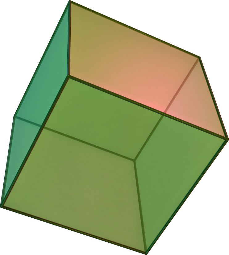
If a micro scale crystal implant is made out of a material that exhibits the piezoelectric effect, then small patches of conductive material are placed on the crystal acting as the ground and extending connections, then a voltage difference from the firing of a neuron would force the crystal to undergo deformation. If a partner device was then to send out a “seeking” ultrasound wave, the backscatter wave that gets returned from the newly deformed micro crystal will be different from that of the non deformed baseline crystal backscatter. Backscatter waves under this central idea of deformation causing a different wave are also highly practical, as neural tissue does not contain areas which may act similarly to the implanted micro crystal, cutting down on background detection noise. It is also possible within this system to exploit the fact that the deformation of the crystal is proportional to the electric field applied, and therefore, if several leads of microwires are created with variable resistances then the deformation within the crystal would be proportional to the voltage. If the difference in the backscatter wave is evident enough, it would be possible to associate each wave pattern to a certain microwire, and therefore, a different position relative to the implant. The simplest method for the creation of the main piezoelectric crystal within this system would be to create a cube-like structure, but this may not result in the most sought after effect, and therefore, several different iterations of the crystal must be created besides the cube-like structure.
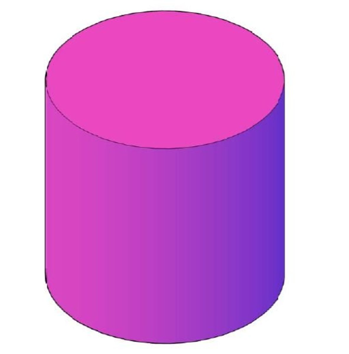
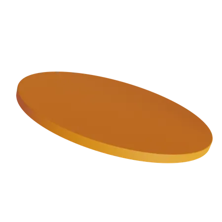
The cube, while the simplest in principle structure to create that will be beneficial to us, is still not as simple as shaping a crystal into a cube. Since the micro scale requirement of the crystal, or rather the entire system itself, so the actual piezoelectric crystal becomes smaller than expected to fit within the size constraints, simple procedures for the shaping of the crystal will be insufficient. Even proper procedure for the production of the crystal will become insufficient, due to monetary and time constraints. For this, a simpler methodology must be examined than additive manufacturing in a super controlled environment, or super controlled subtractive manufacturing methods, to properly shape the piezoelectric crystal of the micro system itself. Instead of these methodologies, it is proposed that we take advantage of the fact that the system itself, as well as the piezoelectric crystal can be grown like an ordinary crystal. We introduce the crystal to a bath solution, and entice a crystal growth on the surface of some outside particle, acting as a stable grounding point for the crystal, to allow the disposition of the piezoelectric material on the surface of the outside material particle. This simplifies the process of the creation of the crystal itself for several different reasons, as we can use outside particles produced by super effective means into certain shapes of designated size, like a disk, a cylinder, or a cube, to properly produce the desired piezoelectric crystal into the desired structure. The fact that there may also exist the material within the finished piezoelectric crystal, may in the long run benefit us in the detection of the backscatter, as both materials will have different acoustic impedances, creating several backscatter waves, but this is just a theory, and will need to be experimentally tested later. So with this, it just becomes a challenge to predict the most desirable shape of the crystal itself, and then produce the system around that shape of crystal. As previously described, a cube will be a simple start, but to add to that, another simple geometry that we may want to consider is a sphere. While more difficult to account for, in terms of piezoelectric deformation, both the order, and the effect of deformation, it might surprise us if tested experimentally. Besides this, it may also benefit us to use some sort of more complex structure for the crystal itself. Besides the spherical, and cube-like structure of the previously proposed shapes of microcrystals, we will also design and produce systems that include a cylindrical crystal, a flat disc crystal, and a randomly grown crystal shape, similar to that most like a snowflake. A table of all of the ideas for the grown shapes can be seen below, as well as the rationale for the design of the particular shape, as well as the predicted size.
|
|
Rationale: The cube-like structure provides simple anchoring points for the tendrils, or the connective points that allow for the extended detection of neural activity around the crystal. It also allows for the most effective deformation prediction of all of the other shapes, as the piezoelectric coefficient can easily be used in such a simple shape. |
Size Prediction and Attachment: The size of this shape will be slightly larger than average, at possibly more than 100 micrometers. The attachment points for the crystal will be on opposite ends of the crystal itself, and the wires will connect directly to the crystal, without the need for an external system. |
|
|
Rationale: The spherical structure, while providing little simplicity within the production of the tendrils, and within the estimation or prediction of backscatter, is a simple shape which provides us with the possibility of producing a vast number of them for testing purposes. |
Size Prediction and Attachment: The size of this shape can be varied from the smallest, to the largest, due to the simplicity of growing crystal spheres. Attachment points for the tendrils will be all over the crystal, producing a “fuzzball” like shape of branching tendrils. It will not require the use of an outside system. |
|
|
Rationale: The cylinder, similarly to the cube, allows for some incredibly simple mounting points for the connective tendrils. Its deformation is also rather simple to predict, and so is a great overall contender for the final shape of the piezoelectric crystal. |
Size Prediction and Attachment: The size of this shape will have to be similar to that of the cube, as the connection points for this shape or on the circular ends of the cylinder. The tendrils will attach to the shape directly, and will not require an outside system. |
|
|
Rationale: The flat disc, while at first appearing as a simple contender, is rather complicated. It is imagined that within the design of the crystal system, the cylinder acts as a collection and reverberation plate, which will produce substantially different ultrasound wave backscatter, when deformed. |
Size Prediction and Attachment: This shape will have a moderate size, as the wires will connect to either end of the circular disk. This system will also require an external system, producing a larger shape than usual, but a better predicted ultrasound backscatter, in terms of the distinct nature. |
|
|
Rationale: The random crystal growth is also an incredibly simple method for the production of the piezoelectric crystal itself. It remains the simplest to grow, and the simplest to attach tendrils to. |
Size Prediction and Attachment: This shape can also vary in size, as the crystal can just stop being grown once the desired shape and size is reached. The tendrils, similarly to the spherical fuzzball, will be grown randomly on the crystal surface. |

As displayed by the table of the image and the rationale for the creation of the specific crystal shape, all of the above will be produced for several different reasons. It is also important to note, that only one of the shapes requires an external surrounding system of a material that is not directly the tendril connective leeds, or the piezoelectric crystal, that being the disc. This is not due to any reasoning, besides the fact that it seems like an interesting idea to consider it almost as a speaker set up. If the crystal is suspended within the larger system, then is deformed, the backscatter from the freely vibrating crystal, suspended by metallic connective wires, would produce an interesting backscatter. It is also important to note that no definite size for the crystals is given within the design parameters, that is for the sole purpose of simplicity within production. Creating a set restriction on the size of the crystals within this stage will be beneficial, but it will be only that, a restriction that the crystals cannot go over. For the purposes of simplicity, a maximum size of 200 micrometers is set as the maximum of the crystals. That places it within the size small enough to not damage the tissue significantly, while still making it large enough to have a distinct shape.
2.4.2.Tendril Design
The micro tendrils are the connective leads that branch from the piezoelectric crystal, and act as its connection with the surrounding neural tissue. Each tendril, as mentioned previously will be designed with a different resistive property, after the successful production of the initial, non variable resistive tendrils has been verified as a functional method of production, allowing for a more accurate detection of activity around the implanted crystal, and therefore a higher spatial resolution. Each tendril must also be designed with a covering, exposing only the very tip of the tendril, as to avoid confusion within detection, as the tendrils will be positioned in the most optimally spread apart places, the detection must occur on the very edge of the area of influence of the device. The microtendril will be made out of several material iterations, and later attached to the piezoelectric micro crystal for simplicity of testing within the tendril system, or rather grown on the microcrystal system, dependant on whether the tendrils are attached to the crystal itself, or the system around it, and each iteration will be made out of a different combination of materials. Gold, silver, and biocompatible polymer will act as the central core of the tendril, and the polymer will be sandwiched between the other conductive material to act as the resistive layer within the system. This sandwiching technique will be continued by altering a layer of resistive polymer and gold or silver. Since each layer of the resistive material has a set thickness, and the resistance of the material is known, it would be possible to determine the total resistance, and alter the deformation of the crystal because of it. It is also important to note, that in this section, the discussion of the production of the surrounding containing system, as previously mentioned, will occur.
The design of the tendrils is simple for smaller crystal structures, such as the sphere, and other crystal structure on which the tendrils can randomly be grown under conditions of constant fluctuation, and no other maintenance of the system of growth is required, but placing the crystals in the tendril bath, and waiting for adequate growth. For other systems, where proper placement of the tendrils on specific locations of the crystal, this process becomes much more difficult than just placing the crystal within the bath and watching the growth of the tendrils. But this can be made easier if the crystals that require precise placement are larger than the crystals which don't, which in this case is true. The crystals which require specific placement of tendrils are larger, and therefore, need larger tendrils, which also means that the crystals can not only be handpicked, but so can the tendrils be hand placed individually on to the crystals. This is exactly what will be done within these systems, and this will also allow for the production of variably resistant tendrils, allowing for equally variable crystal deformation, meaning higher spatial resolution within the system. The problem now becomes the production of the surrounding system around the microcrystal. This is especially important within the case of the flat disc, which requires a circular, dream catcher-like surrounding system for the adequate suspension of the crystal disc. This is an unavoidable difficulty that must be faced head on, and some amount of extended expenditure will be allowed, solely for this purpose. If it is still not possible to create such a system, even with extended expenditure, out of preferably silicon wafers, then the flat disc will be resorted to a simple system that does not contain a surrounding containment system, and will just act as an independent crystal.
2.5.Previous Methods
This section will analyze both the previous methods of production of crystals on such a small scale, but also the tendrils, and when necessary, the surrounding system encapsulation. This will become the background basis for the personal production of the effective system of production later on. In essence, the methods in each system of production are simple, and could theoretically be done with relative ease. Initially, without the use of complicated methods of synthesising the desired crystals, it should be possible to simply include a point of nucleation for the crystals of the desired shape, and slightly smaller of the actual desired size. If this nucleation point is made out of a non reactive, preferably porous material, and produced externally, then the production of the crystals can be done simply, as the constituent chemicals can be mixed under the preferred conditions, and then forced to undergo nucleation of the crystals on to the desired nucleation points. Constant irritation and mixing of the solution tank will be necessary to ensure that multiple nucleation points do not form one large crystal, but otherwise, the process would remain simple, and effective. This can also be done similarly with the tendrils. While the conditions would have to be modified to allow first a deposition of a thin film of the tendril material onto the crystal, and then modified again to allow secondly, the growth of said tendrils of material on the initial surface coat of the crystal. Note that the entirety of the crystal cannot be coated in the metallic material, as then, there would be little piezoelectric effect occurrence, while not zero, it would be so little that it may potentially harm the results. Because of this, care must be taken to ensure that the entirety of the crystal is not covered, and that the crystal remains at least partially exposed, or rather, the coating doesn't connect on all edges. Other methods will also of course be analyzed, to create a more well rounded procedure for the manufacture of the system.
Template Assisted Synthesis:
Template assisted synthesis is similar to the technique already discussed within this section. By employing the use of a “template” for the crystals to grow within, or around, this technique can produce the desired micro crystal shapes. Many such templates exist, such as those which the crystals can grow within, restricting further growth of the crystals while the template exists, and being removed once the template is no longer needed for the growth of the crystal. This technique is viable for the growth of the majority of the crystal structures, as it will simply be removed once no longer needed. This technique will work well, but if not carefully planned, may result in disastrous results within the proper formation of the crystal. Below is an example of the types of structures that are common within this methodology.
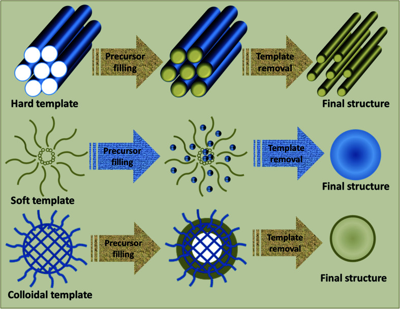
This technique involves the creation of a solution of the precursor chemicals, and then producing crystal structures within, or around the template. This is done by ordinary means, by adding a second agent to kick the crystals into the nucleation process, or to produce the crystals. Furthermore, the technique involves the destruction or removal of the surrounding template via chemical means, leaving only the desired grown crystal, which can further be changed by altering the amount of irritation the crystal experiences during growth, and the temperature at which it is grown.
Sea Urchin Growth Technique:
The sea urchin growth technique is a technique for primarily the growth of the conductive tendrils surrounding the piezoelectric crystal itself, and is a rather simple process for the production of conductive tendrils on the surface of the crystal without first requiring the deposition of a film on top of the crystal. The process is rather simple, and involves introducing previously made particles of the material to the later growth stages of the crystal growth process, and then building up the little particles into long extensive tendrils. This process requires two primary things, the premade particles of the material desired to be grown, and a solution of the material that will be grown. By changing the factors of the solution while the crystal, with several particles of the desired growth material placed on the surface of the crystal, we can entice the growth of the tendrils onto the particles. It must also be noted that this method is reserved for the simpler, smaller particles where the variably resistant tendrils are not required. It also must be noted that this method is primarily for the production of nanoparticles, but with the appropriate changes can be introduced here. An example of the growth process can be seen in the below diagram.
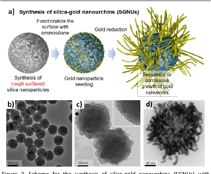
While the above example uses gold, and silica nanoparticles, this can be repurposed for our uses, by swapping out the rough silica nanoparticles for rough particles of the piezoelectric crystal. But overall, this method will produce most of our simpler crystal designs that require tendrils.
Simplified Solution Crystallization:
Simplified solution crystallization is the randomized crystallization of both the piezoelectric crystal, and the tendrils that surround it. This method, while simple, is the one that will produce the least satisfactory results, and will most likely only be used on the randomized crystal structure design of the piezoelectric crystal. This will produce completely randomized piezoelectric crystals, as well as tendrils, and will be done by creating small nano nucleation points within a solution of the primary composed chemical within the piezoelectric crystals to allow for proper growth of the crystal within the solution. This will also be identical within the growth of the tendrils on the grown crystal, and the process needs little further explanation. By varying the temperature, pressure, and the irritation of the solution bath, it may be possible to some extent control the production and growth of the crystal, but this is not beneficial to us, in almost any way. This shape design of randomized growth within the piezoelectric crystal is designed almost entirely as a control for the other crystal shapes, because the randomized crystals may have the ability to form into somewhat desirable shapes. Overall, this method is a sort of last ditch methodology for the creation of the crystals if either time, or money becomes low.
2.6.Production
With the understanding of the required principles, and the rough design of the crystals complete, the production phase can begin. It is also important to note that the design stages of the project were rough, outlined ideas for the actual production, and in this stage of the project, the actual production of the roughly outlined designs could commence, to create better, more effective systems. It is also important to note that because of the nature of the project being somewhat reliant on the engineering principles, and the methodologies of engineering and the engineering cycle, being too reliant on a preconceived plan of some preconceived method of function will be detrimental to us. Instead, we go off of a rough idea, and produce a polished product based on our understanding of the methodologies, and the principles within the concept, and as such, things are prone to change. Nevertheless, let us continue with the production of the microcrystal system within this section, which will primarily outline four things, that being the procedures within the production of the finished systems, of the polished system from the rough idea design stages, as well as extra systems from foreseen issues and complications, the reasoning for which will be outlined here, the potential changes made within the procedure, and the finalized outlining of all of the above details. With this, let us analyze the production methodology used for the creation of the majority of the crystals, and their representative surrounding detective systems, such as the case of the DreamCATCHER system, with the production of the flat disc piezo crystal, and the fuzzball system in the case of the spherical piezo crystal. For the sake of simplicity, only two materials were chosen to produce the piezoelectric crystals, as production of more than two types of crystals, in terms of material, and the testing of these subsequent systems would be far too consuming in terms of resources and time. The two materials chosen were lead zirconate titanate and quartz, the former for its excellent piezoelectric coefficient, and the latter for its simplicity and relatively low reactivity and non toxic nature. Quartz, due to difficulty within its growth, was not produced using artificial controlled production. Instead, in the case of quartz crystal, it was powdered and milled into the desired shape, or rather powder into spherical pellets, onto which the tendrils could then be grown using artificial controlled production. The overall procedure for the production of the crystal quartz is simple, and will be looked over first.
Firstly, a fresh clean quartz crystal was prepared by eliminating any potential contaminants, by firstly cleaning the crystal with distilled and purified water, and then cleaning the surface with a wipe. Then, the crystal was placed into a cleaned bag, and smashed with a hammer to destroy it down into a fine dust. It is not necessary to conduct this with any amount of grace, as our primary concern within this stage of the crystal production is to refine the crystal into more or less workable sizes, that can then artificially be made smoother. This fine quartz dust is then mixed with alcohol of a high concentration, and placed into a powder mill, designed to clean and polish the rough grained powder into a more spherical shape. This powdering stage of the process took several days to refine the quartz powder into spherical crystals of the desired size, but once finished, the excess alcohol was dried off, and the crystals were stored for the next stage of production, tentacle growth. These quartz crystals were made for the purposes of producing spherical fuzzballs, with no desire of producing shaped crystals, and this was left to be produced by the careful production of the artificial controlled growth of the other material. It is also noted that within this stage of production, the spherical, and somewhat irregular shaped quartz crystals ranged anywhere from 100 micrometers, to 250, on the either ends of extremity, but if estimated, the majority of the crystals examined were within the 175 micrometer range, so a bell curve distribution is assumed, give or take 5 percent.
The crystals of lead titanate zirconate on the other hand, were produced artificially, and in a controlled manner. These crystals were produced with the intention of being within different sizes and shapes, to fit within the previously set out approximate design parameters. Firstly, to produce the constituent lead zirconate titanate (PZT) crystal powder, precursor powders were synthesized from mixed metal oxides of lead oxide, zirconium oxide, titanium oxide, with incredibly high purities. These oxides were milled in an isopropanol medium using a vibratory milling machine, with the desired stoichiometric ratios. The milling of these powders within the isopropanol medium allowed for the homogenization of the constituent powders within the precursor lead zirconate titanate powder. Then the milled PZT precursor powder was processed to form the desired crystal growth aspects. To force the nucleation of the PZT crystals into the desired shapes, porous pre-made crystals of the desired shape were used. The simplified version of the procedure goes as follows, firstly the solution from which the piezoelectric crystal would be grown out of is prepared, and is heated to high enough temperature that crystals won't start nucleating spontaneously, and will not start spontaneous growth. Then this solution began being mixed, while steadily increasing the temperature, as to decrease the overall probability of nucleation due to the agitation of the solution, before the properly shaped nucleation points were added. Then fine powders of various different shapes, as were set out by the previously mentioned design parameters of an incredibly small scale, on the order of 15 to 25% of the final desired size of the crystals, at 200 micrometers, we're slowly poured into the solution and allowed to become homogenized within the solution via mixing. When these crystal nucleation points were thoroughly mixed within the solution to produce a homogeneous and even mixture of the desired shapes, the temperature was decreased, and the final precursor element was added in to the solution, to force the sudden nucleation of the piezoelectric crystals around the newly given nucleation points. while the process was not perfect and produced several offshoot nucleation points, and several large undesired crystal growths, the process remained relatively effective through the extended period of time allowed for the nucleation of the crystals around the desired nucleation sites, by increasing the time of crystallization to over 8 hours, and by steadily decreasing the temperature of the solution to force the nucleation of the crystals around the desired shape.
All of the designed shapes were produced with relatively high efficiency within the above procedure. The piezoelectric crystals were grown within the desired shapes, and most were observed to be within the 100 to 125 micrometer size range. This is a much better range than the quartz powdering methodology, in terms of the desired size. The crystal shapes within the previously set out design, randomized and sporadic, were grown without stable nucleation points, rather, powdered glass was added into the solution of random shapes and sizes, and the temperature was decreased without an extended period of time for the allowance of the temperature to decrease in consistent increments. The crystal growth produced from this were much larger, exceeding the desired 200 micrometer maximum size range, but did not go over 400 micrometers in size. The growths were also sporadic and random, producing somewhat undesirably sharp, and potentially damaging crystals. otherwise, with a successful production of all of the crystals, the growth of the tentacles onto the crystal shapes must then be concluded. The tentacle growth was a much simpler process, and required very little time. This is of course relatively speaking to the growth and production of the previous microcrystal structures, and excluding the outside system as in the case of the DreamCATCHER and the flat disc piezoelectric crystal. These were produced at a later time and with much higher difficulty.
The tendrils for the crystal shapes other than the disk, were produced with relative simplicity. The finished crystal growths, or in the case of the quartz crystal, powders, were placed into a solution containing some amount of silver particles of an incredibly small size. The hope within the production of the crystal tendrils was that initially, the rough surface of the crystal powders would be enough to adhere the nanoparticles into the crystals to some degree, but this was quickly found not to be the case. Instead immediately after the submerging of the finished crystals into the silver particle solution, they were immediately transferred into their own solution when applicable, not in the case of the quartz crystals, and further grown at a decreased period of time, to properly adhere the silver particles into the structure of the crystals. After this they were once again taken out of their solutions, and placed into a metallic growth solution that would plate the surface of the particles of silver, adhered to the piezoelectric crystals, into tendril-like shapes. This was once again done over an extended period of time to allow for proper adhesion and force potential growth, but was still a relatively short time compared to the actual growth of the crystals. The finished systems were removed from the solution and stored in labeled containers.
In the case of the DreamCATCHER system, and the fuzzball, the procedure was slightly different. Firstly in the case of the fuzzball, only circular, or rather spherical, piezoelectric crystals were used, that is the quartz crystals, and the artificially grown spherical crystals. Silver particles were not used in the production of the fuzzballs, but the silver was rather grown directly onto the surface of the crystal, and the crystals were agitated while within the silver growth solution to produce the desired tendril-like growths, while the rest of the growth procedure remained relatively similar. In the case of the DreamCATCHER on the other hand, the procedure was nothing like the growth of the tendrils off of the piezoelectric crystals. Firstly, the desired disc crystals, after being grown we're carefully selected for the most optimal, not only size, but also overall shape. Then, with a painstakingly long process, silver wires were carefully adhered to the sides of the discs, which is important to note that they were larger than average, to allow it to become easier for the production of the dreamcatchers, approximately within the 300 to 400 micrometer range. While this significantly decreased the amount of crystals available to us for the production of the dreamcatchers, it allowed for the simpler production methodologies. The attached silver wires were then shaped once again, painstakingly, into a desired circular shape, almost spiral like, with the extending tendrils. Advanced methodologies and systems such as spray on lithography would have made this process much simpler, but monetary constraints prevent the use of such technologies.
With the finished production of the piezoelectric crystals, as well as the piezoelectric systems, we can now proceed with the analysis of the back scatter waves within these crystals, the most vital part of this project. While the actual growth of the crystals is important, it is not the primary goal of this project, and therefore relatively, the time spent within this section is much less than what will be spent, or rather what is spent within the wave analysis portion of the project.
2.7.Theoretical Systems Design
The transducer, or partner device, is the device responsible for the interpretation and decoding of the deformation within the implanted micro crystal, and the neural activity within the vicinity of the detection device. Since the proposal of the system relies on the fact that hundreds of micro crystal detection sites are placed within a small area of neural tissue, as to maximize spatial resolution, a single transducer would not be capable of communicating with the entirety of the devices at once. This is due to the systems reliance on the backscatter principle, as to minimize the size of the implanted microscale detection device, as backscatter relies on an initial seeking wave of ultrasound sent out over small millisecond intervals, a single transducer would not be capable of sending a wave out to every implanted micro crystal. This creates not only a need for several transducers, but for the capability of each transducer to be able to send out incredible focused waves of ultrasound to the micro crystals. This requires the use of transducer arrays, similar to those in medical imaging, but on a much smaller scale. Majority of the technology used in medical imaging will be used, such as the transducer and phased array systems for the regulation and modulation of ultrasound waves. The transducer would then create a connection with a small external device capable of decoding the wave patterns, and sending the data for usable purposes. And while the device that will be designed in this section, and produced if time is not an issue, is not the device used within the actual setting, it will be the device used in the actual, medical use of the system as a whole. As the transducer testing stand will be much larger, due to the necessity to first determine the plausibility of the use of the microcrystals within neural activity detection, it would be unrealistic to assume that it will also be used within the actual medical use of the system as a whole. Within the medical device, a couple assumptions must first be made about the nature of the device. Number one, is that the device will be placed primarily within the skull, to allow for the detection of neural activation within the brain, so the device must either be small enough to be placed entirely within the skull, or if not, must be able to replace the piece of the skull that was removed, or excavated for the placement of the device. Since sizing the device down to any reasonable size to fit within the skull, without negatively impacting the brain, would be near impossible, the second approach will be used to the design. It must also be obviously stated that the device itself will not be responsible for the actual decoding of the information from the ultrasound, as that would complicate, and enlarge the device to unreasonable sizes. The device must, because of this, be able to communicate with an external computer, either via a tethered cable connection, or a wireless bluetooth connection. The latter is rather a nuisance, as the device would still need a tethered connection for sufficient energy, so the tethered approach will be taken.With that being said, let me describe the initial design of the device, hereby known as the head plate, or the transducer. The head plate is a thick device with a small circular port on the very back of the device, which will connect to a specially designed cable, specifically for the purpose of transmitting power to the ultrasound transducer within the device, to receive info from the ultrasound transducer, and to send info to the ultrasound transducer. The device itself is mounted on the back of the skull, replacing a large portion of the skull in that area, and instead screwing into the surrounding skull material. The device would consist primarily of small ultrasound arrays, which would all connect to the central cable, in terms of their reliance for power, and for their decoding abilities of the ultrasound backscatter. To minimize damage and irritation of the brain from the devices, the actual ultrasound arrays rest on top of the brain's dura mater, connected via small cables to the larger head plate device. As a large portion of the back of the skull is removed for the placement of the device, this allows the array to be placed in areas most convenient to the detection of the previously placed crystal detection sites. The cable that connects from the head plate itself, to an external computer must be thick, and almost impossible to damage, as that could lead to serious issues within the individual using the device. Because of this, and because of concerns of potential infection, or even because of the connection ports becoming damaged, the back connective port must be designed to connect to the cable via a stable and screw-like connection, so that the port itself may be covered when not in use. With all of this being said, it is important to note that this is only the theoretical discussion of the potential design of the transducer system within the overarching design of the brain computer interface. Even so, the design of such a system, while currently theoretical within design, will be considered later, if money and time permit.
2.8.Testing Design
To test the completed crystal sensor system, creativity within the testing systems design is key. As the system was not yet anywhere safe enough to be tested in vivo within a living organism, and the growth of neurons was also out of the question currently, due to both technological, and economic restraints, but a source of further research in the future, a new system had to be thought of. As the system was reliant on the electrical activity of neurons, rather than directly measuring the chemical changes within the neurons, although somewhat reliant on these chemical changes for the production of voltage, the system could not just chemically stimulate the crystal, but rather had to electrically stimulate the crystal in the same magnitude that would be present in neural tissues. For several reasons, such as the small size and delicate nature of the crystal, as well as the electronic inability to produce such small changes reliably, directly stimulating the crystal with leads would have been challenging, if not downright impossible. Instead, a different stimulation system was thought of. A shallow bath, full of an electrolytic solution, mimicking that of the brain and ionic channels within neurons and neural tissues, was to be electrically stimulated by two leads of a low voltage, and the distribution through the electrolytic bath was to lower the voltage even further, closer mimicking that of neural tissues, an example of which can be seen below in figure 2.8.1. This system would also allow for simple testing within things such as the travel of the ultrasound waves within tissue, and the interference of tissues on the backscatter waves.
This method would also make the stimulation testing simpler, as the crystal could simply be placed in the bath, and the current turned on. Generally, electricity takes the path of least resistance, but in the case of the shallow bath of electrolytic solution, it will also distribute through the solution based on the electrical potential gradient. This potential gradient is dependent on factors such as the conductivity of the solution, the ionic distribution within the solution, and the temperature gradient within the solution. Something that even further complicates the accurate testing within such a system is the movement of the ions in the solution in the presence of an electric field, and the movement of electrons in the solution. This can be generally described by the Nernst-Planck equation, but the description of such an occurrence would be of no help in the case of the testing. And as such, to simplify the process as much as possible without tainting the results of the experiment, the testing will occur under presence of several monitoring systems, with several crystals in several different areas, and with several different applied voltages, which is further described in the section titled “Backscatter Waves Under Set Conditions”. With this out of the way, it becomes easy to not only create the system, but to predict the needed voltage to simulate neural tissues. Under the assumption that the testing will be done with several different electrolytic solutions of several different concentrations, and of several different chemical and ionic compositions, the below is a description of the calculation of the voltage required in the system under general terms. First, it is important to identify the ionic concentration within the solution, but also the solution conductivity(σ), and resistance(R). To identify the conductivity of the solution, first, some assumptions and approximations must be made, such as the fact that the solution is so well mixed and has so little difference in ion concentration that it can be considered one solid object of identical properties in every section of the fluid, and that the fluid can be modeled as a solid brick of material, rather than a fluid. Conductivity(σ) in Siemens per meter can be calculated using the following equation:
(1.1) σ=κ×A/L
where:
- κ is the specific conductance (or conductivity) of the solution, typically measured in Siemens per centimeter (S/cm).
- A is the cross-sectional area of the solution through which the current flows, measured in square meters (m²).
- L is the distance between the electrodes, measured in meters (m).
Where the formula to calculate κ is given by the following:
(1.2) κ=∑i zi×Ci×μi
where:
- zi is the charge of the ion.
- Ci is the concentration of the ion.
- μi is the ion mobility.
In which the ion concentration can be calculated when the concentration of the electrolyte in the solution is known, and the ion mobility is known from predetermined values and experimentation, under set viscosity and temperature. The resistance can then be calculated using Ohm's law, which first requires knowing the resistivity, described in the following:
(2.1) . ρ = 1 / σ
where:
- ρ is the resistivity.
Further, to calculate the resistance(R) from the known resistivity(ρ), the following equation can be used:
(2.2) R=ρL / A
where:
- is the resistivity of the solution.
- L is the distance between leads.
- A is the cross sectional area of the solution between leads.
With the help of the above equations, it is now possible to further continue our predictions of the voltage of the bath under a set voltage. Note that the above equations may not always be applicable, such as in cases of uneven ionic distribution, and uneven temperature gradients. In our case, neither of these things will be an issue, and as such, will not be bothered in modeling, but if it was necessary for someone trying to replicate, or apply this strategy to their own experiments, the following methods can be applied. Firstly, within a temperature gradient, integrating over the temperature dependant conductivity over the temperature gradient, as the conductivity of an electrolytic solution varies with temperature. Secondly, when considering the non uniform ionic distribution within an electrolytic solution, consider using the Nernst-Planck equation, which considers variables such as ion concentration gradients, ion mobility, and electric field strength to describe the flux of ions in a solution. Nethertheless, let us continue with the modeling of the solution and the voltage drop across it. Ohm’s law can be applied to calculate the voltage drop across the solution, using the following:
(3.1) I=V / R
Under the assumption of uniform resistance distribution, we can consider the voltage drop across the solution to also be uniform, therefore, the voltage at any point between the leads can be calculated as follows:
(3.2) V=IR
With the use of all of the above equations, it becomes possible to calculate the required voltage within the leads to accurately simulate the environment of neural tissues. Further environmental simulation, such as the simulation of the soft, gelatinous composition of the brain can be modeled using things such as common gelatin, like the type used in the creation of pudding, or jello. If this powder is instead mixed with the electrolytic solution, it should not impair the travel of the electrons substantially, and should help with the testing of the backscatter wave analysis, the backscatter wave analysis under set conditions, and the safety testing portions of the testing, although that would not require electrically conductive “jello”, and it would suffice to have it simply to analyze the potential dangers within shifting of the crystal, and the potential damage from implantation, although that is discussed further in its respective portion of the paper.
2.9.Testing Systems Production and Testing
The production of the testing system was rather simple, and required very little actual work. The testing system, or testing stand, was produced by first creating a non reactive, non conductive, shallow bath that would allow for the proper placement, and testing, of the micro crystal. A small bath, 30cm across, and 5cm deep, was first designed, and 3D printed out of PLA plastic. This bath was then sanded smooth with increasingly high grits of sandpaper, and was washed thoroughly between each sanding. It is also important to note that the bath was printed out of one hundred percent infill, and at a higher than normal printing temperature, to properly adhere the layers to each other as well as possible. After this was done, and the plastic was sanded smooth on the exterior, and semi-smooth on the interior, the entirety of the bath was covered in a non reactive, non conductive, ultraviolet cured resin. This was to prevent potential spillage, and to further smooth out the surface of the bath for both testing, and aesthetic purposes. The smoother the inside of the bath was made, the less potential for the ultrasound wave backscatter from the bath itself, and not the suspended crystal, to create erratic and confusing energy patterns in the ultrasound transducer array. After this process was completed, and a finished testing bath was created, a stand for the ultrasound transducer array was created. This was once again a 3d printed system, was was essentially as sliding stand, which allowed for the vertical movement of the transducer array, from the very surface of the bath, to several centimeters above the surface of the bath, accounting for the extra space that the transducer array itself would take up, shown in figure 2.9.1 below.

After the completion of the stand, the bath, and essentially the probes to produce the electric potential across the liquid within the bath for the stimulation of the crystal, more or less, as the actual production of the voltage did not require any special means, and could easily be produced with store bought means, the most important factors now, became the production of the transducer system, and the electronics behind it. As this project is primarily the detection and determination of whether the piezoelectric effect within micro crystals is detectable enough to be applied within medical use, and because the actual medical system will also be comprised out of several ultrasound transducers located in different areas of the tissue being monitored, it is reasonable to overdesign the transducer system. Because of this, it will be composed out of several ultrasound arrays, composed around a central point, to create the highest degree of accuracy within the system. These arrays will be store bought circular arrays, with the capacity of two way transmission and detection of the ultrasound waves, with some degree of accuracy. These arrays will be connected to a central computer responsible for the analysis of the waves received from the transducers, and will also be responsible for the modulation of the waves that the transducers produce. This was produced, and the individual transducers were placed on another 3d printed interchangeable head, which screwed into the sliding stand, as to allow for the changing of the central pressure point of the ultrasound arrays. With this constructed, a system for the continual change of the ultrasound wave was coded, to allow for the cycling of testing in combination with the electrical fluctuation to induce change within the crystal without human assistance. This significantly cut down on time of testing, as the testing could run for several hours on end. The ultrasound algorithm essentially created short pulses of ultrasound waves at increasingly high frequency and energy, starting from the 20KHz range, climbing upwards into megahertz, to induce more precision within the device. Beyond this, the phases of the ultrasound array, within the periods in which they were not sending out the ultrasound wave, were listening so to speak, to the potential backscatter. Each array fired in sequence of each other, allowing for optimal detection of the backscatter wave, and optimal testing of the angles within the system. Furthermore, the actual electrical stimulation of the crystal happened in randomized intervals of stimulation, as to throw off potential bias or sources of contamination within the finished data. It is also noted that each crystal configuration was tested like this, several hundred, and in some cases, thousands of times to further produce most accurate results within the testing. All of this is further discussed within the wave backscatter analysis section of the project, and this is just firstly, a short description of the happenings of the testing, and the testing procedure. With that being said, the following is a shorthand description of the procedure taken when testing the crystals.
Step 1: Firstly, everything must properly be prepared for the testing of the crystals. This includes the proper setup of the bath, by thoroughly washing it with distilled water to clear it of any contaminants, and preparing the electrolytic salt solution, and placing it within the bath. The leads are also placed within the bath, and the computer program for the random stimulation of the crystals is also connected, as well as the computer system for the activation and detection of the wave backscatter. The electrolytic solution is created with common table salt, cleaned from any chemical impurities, and the resistance of the solution is calculated using the known weight of the solution. The algorithm for the electrodes is also regulated in accordance with this, running through the random pulses of activation.
Step 2: The crystal sample is placed within the solution, and the transducer stand is placed on the surface of the solution where the crystal sample was placed. It is imperative in this step that the sample, placed within the solution, is not only free of outside contaminants, but is also central to the transducer array system, as otherwise, the ultrasound waves will not interact properly with the system.
Step 3: This completed system is then placed into a sterile field, a clear covering, or rather a box, which was removed of all potential contaminants of particulate matter, and the automated testing regulated by an outside computer can commence.
Step 4: After the preparations for the testing have been made, the computer algorithm is activated, and so is the electrical stimulation probe algorithm. The experiment is then left after verification that everything is active, and properly functioning, to run for several hours, to not only give each frequency and energy level several pulses to properly verify the results, but to be able to cycle through the frequency and energy range.
Step 5: After all of the required testing is complete, the system is disassembled, and the bath is thoroughly washed with distilled water, to make sure as to remove the previous crystal sample from the bath, and prepare for the next stage of testing.
Step 6: Repeat the above stages with a different crystal sample.
3.Results
3.1.Wave Physics and Beyond
The humble wave, the carrier of energy within a system, is the basis of this project, and is arguably the most crucial part behind the proper operation of this system, besides of course, the actual design of the wave producing device, and the backscatter producing device. Understanding the physics of a wave, and physics of a wave under set conditions is crucial in proper testing, and understanding of the results, such as sudden changes in backscatter wave data. A wave, in the propagation of a gelatinous medium such as flesh, or the brain, is one that is very difficult to model. Even a propagating wave in a standing medium of identical properties is difficult to model, and when fluid dynamics, to a certain extent, such as is the case in the gelatinous substance of the human body are involved, modeling becomes even more difficult. For this, complicated modeling algorithms must become involved, as well as some amount of leniency within predictable accuracy of mathematical equations. But nonetheless, it must be addressed to first understand the physics of the ultrasound waves, and to be able to some extent predict the potential results within testing of the system. As such, this portion of the paper will try and address the physics of a wave, both mechanical and classical waves, but also more abstract ideas of waves and wave propagation, although in less depth, the physics of attenuation, energy dispersion, wave scattering, and backscatter wave physics. Although all of these topics will be briefly covered, it is important to remember that this is still primarily an engineering paper, describing the engineering process, and as such, much more time will be devoted to the actual testing, resulting values, and the creation of a functional, final system.
3.1.1.Classical and Mechanical Wave Physics
A wave, in classical physics, or classical mechanics is described as a propagating disturbance of one or more quantities, and is the definition and focus of a wave most important in the design of this project. For our purposes a wave can be understood, and modelled as a transverse mechanical wave traveling through a relatively rigid medium, that being an oscillating vibration within the medium at some set frequency, wavelength, and energy. Put more simply, it is a pressure disturbance traveling through a specified medium via particle-particle interaction. This can create fronts of high pressure, and vibrational energy, but also create areas of lower vibrational energy, as is the nature of a wave to oscillate. Mechanical waves traveling through a set medium can be modelled rather simply, and in this case, with the use of ultrasound, the equation used is the acoustic wave equation, which governs the propagation of acoustic waves through a medium of set properties. The function describes the evolution of acoustic pressure as a function of a certain point in space, and time. After the specific type of wave equation is determined, in this case the acoustic wave equation, but in other cases different wave equations are applicable, it is important to identify and incorporate the medium properties in which the wave will propagate through. Factors like different densities, elasticity, and other indices must be incorporated into the equation. In this case, these conditions will be examined in a later part of the paper, and corrections for these things will not be made in the initial acoustic wave equation. For a numerical method or analytic solution, different techniques must be used to solve the acoustic wave equation, but generally, if the equation is simple enough, analytic solutions may be possible. The following is the simplest form of the acoustic wave equation, described as a partial differential equation:
(4.1) ∂^2p / ∂t^2 = c^2 (∂^2p/∂x^2)
where:
- p is the acoustic pressure.
- t is time.
- x is the spatial coordinate.
- c is the speed of sound in the medium.
While the above equation can vary, it is the simplest method of describing the propagation of a one-dimensional wave through a homogenous medium of identical properties. The first term represents the second partial derivative of the acoustic pressure wave with respect to time, indicating the pressure waves change throughout the medium throughout time, essentially describing the acceleration within the pressure medium. The second term represents the second partial derivative of the acoustic pressure wave through the medium in respect to space. In essence, it is the description of the curvature of the pressure wave in space. When the partial differential equation is viewed in full, it explains the acceleration of the pressure wave is proportional to the curvature of the pressure wave, dependent on the medium, and the speed of sound squared within the medium. This is of course the most simple description of the acoustic wave equation, assuming a one-dimensional wave, but a three dimensional wave becomes substantially more complicated, with the following equation:
(4.2) ∂^2p / ∂t^2 = c^2 (∂^2p / ∂x^2 + ∂^2p / ∂y^2 + ∂^2p / ∂z^2)
where:
- p is the acoustic pressure.
- t is time.
- x is the left/right spatial coordinate.
- z is the up/down spatial coordinate.
- y is the inwards/outwards spatial coordinate.
- c is the speed of sound in the medium.
In which the first term still refers to the acceleration of the acoustic pressure wave in respect to time, but now, the spatial dimensions refer to the curvature and change in pressure wave in all three spatial dimensions. This can be visualized using several different techniques, including a space-time diagram which plots the propagation of the wave in the medium over a set period of time with set conditions. To better visualize this, a computer program will be written in a later testing section of the paper to not only describe the initial wave within the medium, but the wave within the medium after backscatter, to better understand and analyze the data presented during testing of the microcrystal. Overall, the understanding of the acoustic wave equation is important within the reaches of this project for several different reasons, and becomes even more so when corrections for attenuation, energy distribution, and inhomogenous mediums are considered. A primary purpose of the understanding of the equation of the classical wave under different ideal, and non ideal conditions, is the explanation of backscatter wave data, and wave data predictions, as well as 3d modeling systems. This allows the system to create better, and more accurate correlations in data from backscatter. The understanding of the wave equation also helps in the design, and outcome predictions of the design of the detection site system.
3.1.2.Wave Attenuation and Corrections
Wave attenuation is the description of the loss of energy or concentration of a wave, in this case of acoustic and mechanical nature, as it propagates through a medium. This attenuation is important to understand within the context of this project for several reasons, primarily, for the correct energy level of the seeking wave from the transducer device, and for the complete understanding of the results of the testing of the system. Attenuation, for our purposes, will only be evaluated from three primary contributors. Although more than these exist, even three is more than overkill, for several reasons. The biggest being the fact that these equations and corrections are only helpful within the initial choice of energy of level within the initial incident seeking wave, and for the understanding of the results within the analysis portion of this paper, both of which can be done experimentally, and with a higher degree of accuracy in the realm of engineering a final, functional system. Nevertheless, let us first discuss the three primary contributors to wave attenuation within a system, and how they will be compensated for. First, and one of the biggest of the three contributors of wave attenuation, there is absorption. Absorption of the wave occurs as it continues to propagate through the traveling medium, when the acoustic wave is converted to other forms of energy, primarily heat. While this is minimized with the use of ultrasound, it is still not entirely avoided, and is still a significant contributor to the reduction of the intensity of the wave as it propagates through the medium, influenced by several factors. The second factor behind acoustic wave attenuation is scattering of the wave in the medium. Now, scattering is a complex factor of wave attenuation that cannot be entirely predicted without some amount of experimental data, as it is the redirection of some portion of the wave within the medium from its original path of propagation due to a sudden change in the medium's acoustic impedance. Preferably, neural tissue like that of the brain would be homogenous, an ideal substance for the wave to travel through, which with a high degree of accuracy can be predicted, but it is not. The human body is full of imperfection, and at times these imperfections may seriously impede our fundamental theoretical understanding and prediction of the situation, but they will not impede our experimental testing. Truly, the only thing we must understand about scattering as a correction for the travel of the wave through the medium, and not as the occurrence of the wave being redirected from our piezoelectric crystal, is that it can occur, and how to spot it within our results. The third contributor to attenuation is viscosity, or viscosity of the medium the wave propagates through. Viscous losses occur due to the internal friction within the medium as it responds to the oscillations of the wave, resulting in lost intensity and energy of the wave, as the energy is converted to heat. While similar to absorption, the two processes are slightly different, and are modeled slightly differently, but end in the same result, lost energy in the form of heat, which is both dangerous to the function of the system, but to the biological tissue around it. With this knowledge, the address of this attenuation and energy loss of the wave as it propagates through the medium will be discussed in the following subsections, split up into the primary constituents of the three factors.
3.1.2.1.Wave Energy Dispersion/Absorption and Corrections
The dispersion and absorption of a propagating wave of acoustic energy within a system, or rather a medium of choice of travel of the acoustic system, is, to be quite frank, quite an annoying complication, and source of needed correction within the adequate choosing of the energy of the propagating wave, for the purposes of ultrasound backscatter, and for the purposes of accurate detection of irregularities or deformation within a microcrystal embedded within neural tissue. The absorption and the dispersion of the propagating wave within said system can of course be accounted for, and needs to be accounted for, for several different reasons, the primary of which being the fact that if the too much of the waves energy is dispersed or absorbed within the system, this excess energy could have negative consequences on the medium, in this case biological tissue. For this reason the adequate corrections within the formulation of the energy of the propagating wave within the system must be accounted for, without overestimating the absorption and dispersion of the propagating wave within the medium and subsequently within the system, so the wave still has the potential to carry vital information within its back scattered state about the deformed micro crystal embedded within the tissue. The second potential danger, or rather potential nuisance within the need for the correction of the energy dispersion and absorption of the acoustic wave within a medium, as well as within the initial point of backscatter from the micro crystal, is that too much of the propagating waves energy is dispersed or absorbed through the medium, and the remaining acoustic wave would not be capable of adequately transmitting the information from the deformed micro crystal back to the transducer, or rather carry any sort of vital information. Within the case of the initial design of the micro crystal transducer system, the latter is a much more important factor to consider when considering the absorption and dispersion of the acoustic wave within the medium, as our primary goal is to determine whether ultrasound backscatter from a deformed micro piezoelectric crystal even has the potential to carry the necessary information that implies the activation of a neuron near the embedded micro crystal.Therefore, when accounting for the wave energy dispersion and absorption within the medium, as well as the initial point of backscatter, we will focus primarily on the energy lost from energy dispersion and absorption, and the minimum amount of energy required within the wave to still have the potential to carry vital information, without being entirely absorbed or dispersed while propagating through the medium.
On that note, let us consider how we must account for the dispersion and absorption of the propagating acoustic wave through the medium under several different conditions, or rather reasons. Dispersion within a system occurs primarily because of a waves nature to propagate from a central point, as a wave, especially of acoustic nature, traveling within a medium will not travel as a flat straight wall through some coordinates of space over time, but will rather propagate through the space, or rather the medium, in a spherical fashion from the center point of origination. Although methodologies for the concentration of the acoustic wave within a system do exist, and they will with certainty be utilized within the scope of this project for the concentration of the acoustic wave beam to the desired micro crystal embedded area, it is still important to understand that because of a wave's nature and the oscillations within a wave moving through a medium through space, that the wave will not act as a flat wall, but the wave will rather act as a curved propagation through the medium, through space. This energy dispersion due to a wave non-flat, wall like nature, Is the direct result of the nature of an acoustic wave, which is created through the use of a vibrating material, creating areas of high pressure, followed by areas of low pressure. This can be demonstrated as a vibrating string oscillating between a right and a left position, when within the right position the way of creates a compressed state within the medium, and within the left state creates an area of low compression within the medium, which is the reason for the oscillation of a wave as it travels through a medium. A simple diagram of these processes can be seen below in figure 3.1.2.1.1.
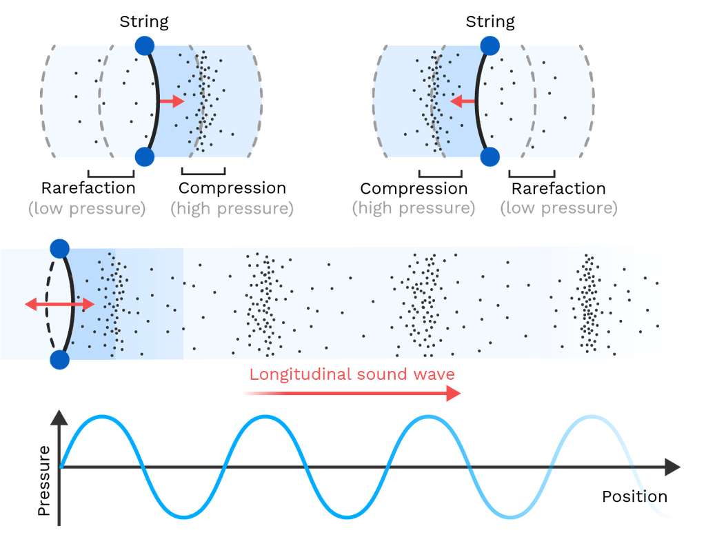
Put more simply, the oscillation of a wave acoustic in nature, within an elastic medium, such as biological tissue, which is relevant in this case, is created by the distributions of high pressure wavefront within the propagation of the wave, and of low pressure back end wave fronts within the wave. This travel of energy throughout the medium as a wave, propagating, and oscillating, creating differences in state of compressed and uncompressed areas within the medium, results in vibrational energy, which we will touch up more on when discussing the absorption of the energy, but for now it is important to note that the vibrational energy within the high pressure wave fronts of the wave, creates slightly irregular motions of travel within the particles that the wave is creating the compressed and uncompressed states in, creating a spread of the waves energy. A good approximation for the distribution of a waves energy within an elastic medium, such as biological tissue, is by incorporating the attenuation coefficient of the material into the three dimensional wave equation, which accounts for the energy loss of the wave as it propagates through the medium due to all of the factors of wave attenuation, dispersion, and absorption, as well as to some degree scattering, but this cannot be entirely theoretically modeled due to the nature of scatter within an inhomogeneous medium. Because the attenuation correction within the three dimensional wave equation, and within any sort of simulation of a propagating wave is the summation of all the factors of wave attenuation, it can only be fully considered after considering all factors of attenuation, and, because of the lack of theoretical foundation in the consideration of the attenuation coefficient, it will be determined experimentally. For now, it is just important to understand the dispersion and absorption of a propagating wave through a medium for the purpose of understanding results, and the effect of highly concentrated areas of neural tissue when concentrated with the micro crystals.
Now that we have thoroughly discussed wave dispersion within a system of a propagating wave within a semi elastic medium, it is time to discuss the second contributor to the wave attenuation corrections made to the three dimensional wave equation, absorption. In relation to the energy of the wave, absorption relates the energy lost within the wave as it propagates through the medium, due to the energy translation of the wave into heat. As the wave oscillates, and travels through the medium As an oscillation of pressure difference within the wave, due to the nature of the creation of the acoustic wave within the medium, the areas of high pressure, in conjunction with the areas of low pressure, create vibrational energy within the particles of the medium. Usually, this vibration is caused with air particles, and most equations to simulate and correct for the wave attenuation due to energy absorption correlate the energy absorption under the assumption that air is the medium through which the wave propagates through. In the case of soft, semi-elastic biological tissue, such as that of neural tissue, absorption becomes less of an issue, especially within an acoustic wave, As particles comprising the oscillation of the waves' high and low pressure areas, have less freedom of movement than in air. This results in lower energy transition from the acoustic wave propagating through the medium, into heat energy. In most cases, energy absorption from a wave propagating through a medium, especially of acoustic nature, is resultant from the energy transition of the wave into heat due to the oscillating pressure differences of the wave creating particle vibrations, or heat energy within the medium. Although in this case, absorption of energy is still primarily that of the transition of energy from the propagating acoustic wave within the medium to heat energy, this is much less prevalent due to, as previously mentioned, the higher restrictions of particle movement within the semi-elastic medium. Because of this, energy absorption within the system can be overlooked, or even entirely ignored, beyond a certain energy level of the wave. With this knowledge, we can further understand not only the results, but also the safety testing of the finished system. But without experimental information regarding the medium itself, we will still not be able to figure out the wave attenuation coefficient for adequate correction of the wave attenuation, and as such, this knowledge is mostly here for the purpose of understanding, and safety testing.
3.1.2.2.Wave Scattering and Corrections
Wave scattering as a factor of wave attenuation within a medium occurs primarily due to small material impedance differences to acoustic waves within the medium. In other words, it is primarily caused by the irregularities of material properties within a medium, and the subsequent scatter of the wave from these irregularities, be it back in the direction of the transducer, causing confusion within the detection of necessary backscatter. The second, and still prevalent producer of wave scattering within a medium, is the tendency of the three dimensional acoustic wave to act as if it produced from a singular point, and propagating in a spherical shape, causing not only loss of energy as the wave travels deeper within the medium, but also a less concentrated wave, due to the particle interaction that has been previously discussed. Because wave scattering occurs primarily due to the irregularities of acoustic impedance within the chosen medium, and this cannot be known beforehand, we cannot model the acoustic scattering of the wave before getting experimental results with, and without the implanted crystal. It is for this reason, that a proposed implantation methodology be acknowledged within the use of the system when used clinically. The medium, or the neural tissue, which in most cases will be the brain, will before the implantation of the microcrystal in the desired area must first be mapped out over a series of ultrasound waves. These waves, when scattered off of irregularities, provide a solid foundational starting point in understanding the acoustic impedance difference within large portions of the tissue. This allows the proper positioning of the crystals in areas where acoustic impedance will not severely and detrimentally impact the acoustic wave backscatter of the crystals under deformation, or activation. This methodology of scanning the area out using ultrasound backscatter also allows for proper detection of necessary, and vital information from the backscatter, as the backscatter information can be layered over top of the background backscatter, and the difference can be noted to cut out unnecessary information, and isolate the necessary information from the backscatter system. As there is not methodology for theoretically predicting the scatter, or mathematically compensating for it within the estimation of the backscatter system, the best we can do in this section is the description of what would be necessary within actual clinical trials, and as this project will not conduct in vivo testing, this cannot even be addressed in all that depth within the testing portions of this project.
3.1.5.Backscatter Wave Physics
Now, with our understanding of the wave equations in both one spatial dimension, and in 3 spatial dimensions corrected with the equations for the correction of the wave under different conditions, and imperfect testing environments, to account for factors such as natural wave attenuation within a medium, the subsequent wave scattering effect within the medium, and the overall dispersion of the wave, we can begin to analyze not only the equations for wave backscatter, but to start to model a system for the prediction of the wave under all of the above influences. Although this is not the primary focus of this section, and is discussed in the greatest detail in the backscatter analysis, and backscatter analysis under set conditions sections of this paper, it is briefly mentioned, as all of the factors for a successful digitized computer model have been evaluated. Overall, this section is a description of the phenomenon known as backscatter, and the mathematical description of the backscatter, of a specifically acoustic wave within an inhomogeneous and homogeneous tissue, from the sudden change in material properties. Although this is a good overall definition of what the backscatter wave within a system is, a more appropriate, well defined, and official definition of the backscatter effect is the reflection of a signal back in the direction from which it originated. This is true for things such as waves and particles, back in this case, or analysis revolves around the specific backscatter of a wave. To better understand the backscatter wave, which is so crucial to this project as the fundamental, or one of the fundamental principles of materials and energy, besides the reverse piezoelectric effect in the functioning and idea behind this project, let us first imagine a set space, with a wall some distance away from a source of acoustic noise, like in the figure 3.1.5.1 below:
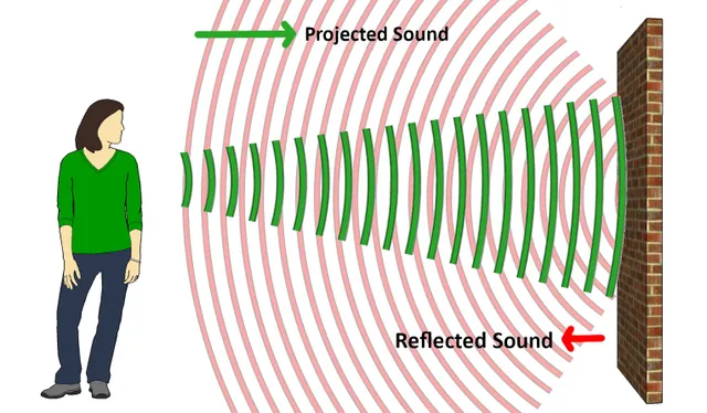
As is portrayed in the above image, a source of noise is positioned some set distance from a wall, within a set space filled with ordinary air, but no other contaminants. Note also that the wall is floating freely within this space by some imaginary force that we cannot interact with, so that there exists no floor within our example. These conditions, fairly well, mimic the conditions that our microcrystal of piezoelectric material experiences within neural tissue. The air in this case acts as the medium, which in the case of the crystal is the neural tissue, and the wall mimics that of the crystal, which in the case of the crystal, is, well, the crystal. If an acoustic wave was sent out towards the wall, then logic dictates that some amount of the wave will bounce back, such as is the case in echo, so the device, or in the case of echo, ourselves, will receive the information from the bounced back wave. In the case of echo, we receive a slightly distorted version of what was initially said, and in the case of ultrasound backscatter we get a different energy wave configuration than what was initially sent. This difference in wave backscatter is an essential idea in the design of this project, and is the driving force behind the design of the microscale crystals reliant on the piezoelectric effect for their deformation in the situation of an applied voltage, resulting in a different backscattered wave from the crystal. With a now more concreted understanding of the importance of the backscatter wave, and the analogy off of which the mathematical formulas and descriptions can be based, we can now begin to describe not only the actual backscattered wave with more mathematical precision, but its changes from initial changes in the microcrystal off of which it bounces with more accuracy, for the purposes of not only understanding the basis of the phenomenon, but also for the more concrete understanding of the results and digitized computer modeling of the system. As such, and as done previously, let us first analyze a simple description of backscatter, and continually work our way up in difficulty, complexity, and accuracy of the system.Within wave backscatter, or more accurately wave reflection in a system, there exists two primary types, specular reflection, and diffraction reflection. Specular reflection is the reflection that occurs when a wave interacts with a completely smooth surface, resulting in a completely expected wave return equal to the angle that the wave initially interacted with the flat surface, in comparison to the angle of incidence. Although this type of wave reflection within a system is incredibly simple, and is therefore incredibly simple to mathematically model, we will not even consider it, for the sole purpose of its simplicity, and unrealistic nature within a wave return system. Diffraction, or the wave return within a system from an uneven surface, or backscatter, is a much more realistic case for the actual happenings within a system. To first understand the directional properties of the backscattered wave, let us first analyze the wave from the Kirchhoff approximation, which is a methodology for the description of waves backscattered from an uneven surface, without needing to solve the full wave equation at every point on the surface, which becomes incredibly computationally intensive. The Kirchhoff approximation can be described by the equation below:
(8.1) Pscat(r, θ) = e^ ikr / 4r S integral Pinc(r',θ')(∂G / ∂n' - ∂G / ∂n)dS
where:
- Pscat(r,θ') is the scattered pressure field at a point specified by distance r, and angle θ'.
- k is the wavenumber.
- r is the distance from the surface, to the point of observation.
- S represents the surface.
- Pinc(r', θ'') is the incident pressure field at a surface point specified by the distance r’, and angle θ'’.
- G is the Green’s function, representing the pressure field due to a point source, and observation point.
- ∂G / ∂n' and ∂G / ∂n are the derivatives of G with respect to the normal vectors to the surface at points r and r’.
The above integral of the Kirchhoff approximation is the common methodology of choice for the mathematical description of the backscatter wave off of an uneven surface. At the surface of some chosen object for the calculation of the approximation, an incident acoustic ultrasound wave interacts with the uneven surface and its irregularities, causing the diffracted backscatter of the wave. The acoustic pressure field generated by a source point, described by the Green’s function, demonstrates a solution to the wave equation, analyzed in previous areas of the paper, which allows for the easier processing, and better approximation of the waves behaviours during backscatter. The integral within the Kirchhoff approximation computes the scatter pressure field at some observation point P, by taking the summation of all contributing points from the scattering surface S. It is also important to note that the Kirchhoff approximation assumes that the viewed, or calculated point is distant enough that the backscattered wave dominates over the incident wave, making the initial baseline of the incident within measurement and approximation negligible. Furthermore, S, or the scattering surface within the approximation can be represented in a numerous amount of different ways, some of course, more complex than others, but that does in no way discredit, or make the less complicated surface descriptions any less useful. The surface can be easily approximated using simple parametric equations, that might aid in the assistance of predicting ultrasound backscatter in simple crystal geometries and testing systems, but not in much else. It is also possible to describe the surface as a polygonal mesh, or as a complex surface that approximates a portion of the surface using systems of topology. Or it is also entirely possible that the surface can be represented in a flat graphed out plane using simple, human approximations and viewings of the crystal geometry from a microscope. While we are not entirely done talking about backscattering, in the ordinary sense, and will return to it at a later time, first, let us analyze a different form of backscatter. This form of backscatter would be much more useful in the accurate interpretation of signals from our micro piezoelectric crystals because it is reliant on the small size of the material being analyzed via ultrasound. this form of Backscatter is called Rayleigh scattering, and is the process of waves of acoustic ultrasound being sent out equally in all directions from a small material, or object with different material properties than the initial traveling medium of the acoustic wave, due to the materials substantially different size to the wave of ultrasound. Rayleigh scattering is a special type of scattering that goes equally and all directions from an initial scattering point, and it occurs when an object's dimensions are much smaller than the initial beam's wavelength. A higher frequency sound beam aimed at the object will also scatter more in terms of Rayleigh scattering, then a lower frequency sound beam. This information will not only be helpful in determining the ideal frequency and energy level of the initial seeking wave, but might also aid in the testing of micro piezoelectric crystals within a highly concentrated area of neural tissue, in terms of the quantity of crystals within that area. Rayleigh scattering can also be classified as diffuse scattering, and occurs because of the resonation of the material with different acoustic impedance than the surrounding medium from a wave of ultrasound with some set frequency, when the material of different impedance is smaller than that of the wave. This methodology of analysis will be helpful in the testing of the piezoelectric crystals under different energies and frequencies of waves. This methodology for analysis will also be helpful in understanding chain backscattering within clouds, or highly concentrated areas of the crystals within tissue. Nevertheless, the intensity of waves emanating off of an object within Rayleigh scattering as a phenomenon can be expressed using the following mathematical description:
(8.2) I = I0(1+cos^2θ / 2)(w / pi4)^2(deltaZ / Z0)^2
where:
- I0 is the intensity of the incident acoustic ultrasound wave.
- θ is the scattering angle.
- w is the wavelength of the incident sound wave.
- Z is the difference of acoustic impedance in material of scatter and travel medium.
- Z0 is the characteristic acoustic impedance of the medium.
The above equation is the mathematical description of the Rayleigh scattering phenomenon from a scattering particle, specifically within the calculation of the intensity of the scattered acoustic wave. The equation takes into account the angle at which the specific backscattered wave is viewed from, the acoustic impedance of both the travel medium, and the difference of impedance between the particle and the medium of travel. As within the scattered particle, the effect of Rayleigh scattering is approximately equal in all directions, besides the direction is which the incident wave impacted with the particle, as a disproportionate amount of energy continues to travel through the particle, resulting in a slightly stronger over all scatter in that direction, the equation can overall be used to calculate the intensity of the backscatter wave in any point of the particle. With this final piece of the puzzle now known, we can begin complex calculations for the predictions of the backscatter of the ultrasound within a congregation of crystals, first, taking into account different acoustic scattering and attenuation phenomenon within a medium, the wave equation within the medium, and the resulting backscatter, we can follow on instance of the seeking wave, and follow it through the system to come back at out backscattered end result, calculating the loss of energy within the system as we go along in time, and as the waves continue to make their way around the cluster of micro crystals. We can also to some degree, predict the resultant backscatter difference from a deformation within one, or more than one crystal. And, while these prediction and evaluation systems are useful, they remain complicated, and more so as a last resort for the verification of results within the system. The number one methodology still remains computer simulation using these equations, and the direct testing of the system, which are all discussed in the next section of the paper.
3.2.Backscatter Wave Analysis
The backscatter wave analysis portion of the testing is the determining factor behind whether or not the system, or even the idea behind it, has merit. The basic testing procedure for the system would include artificially stimulating the microscale crystal on roughly the same voltage difference it would experience in the firing of a neuron, on the scale of 50 to 100 mV, and simultaneously activating the transducer device. This would be done after initial waves of the non deformed crystal are catalogued as a comparison for the waves in relation to the deformation within the crystal. Although the expected waves can be modeled mathematically, the model is simple and approximate, because research in this field is not extensive. The amplitude, frequency, and timing of the backscattered waves all need to be carefully catalogued on the basis of the non deformed crystal, and any change at all after deformation must be noted. Although it is expected that if the seeking ultrasound wave interacts with the crystal on its immediate deformation, the backscatter wave gains a small amount of energy compared to the non deformed crystal. If the seeking wave hits the crystal a slight period of time after its initial deformation, it is still expected to gain energy, but a very small amount, and this trend is expected to continue until a certain point within the crystal timeline of deformation when the effect may either reverse, or stop at its initial baseline. Of course these are just predictions, and the actual analysis of the wave backscatter is a far more complex process. Before we can analyse and discuss the results from the backscatter wave testing, let us first go over a designed analysis system, for this exact purpose of backscatter wave analysis.
The three primary forms of ultrasound backscatter that exist when talking specifically about small particles on the microscale, are specular scattering, diffuse or Rayleigh scattering, and diffractive scattering. For our purposes, we will not entirely omit specular scattering from our considerations of ultrasound backscatter within the system. While it is true that specular scattering will not be an entirely correct definition of any of the types of backscatter within our system, it is a good approximation of the approximate scattering within the DreamCATHCER system, as it relies on a flat disc suspended within a wire coil system. This flat disc, will more so act as a specular scattering point, over any other of the points. Specular scattering is the most simple to model, because if the impedance of the crystal is known, and the impedance of the initial tissue traveling medium is known, then it is also known the boundary impedance difference between tissue and crystal. Diffuse scattering is still relatively simple to model, because once again, if the impedance of the traveling wave medium and the crystal structure are known, then we know how to mathematically model the scattered wave. Although these calculations are computationally intensive, and because they are the most required for our purposes, later a new mathematical method will be proposed for the modeling of such scattered waves using simpler methods, omitting the need for PDEs. Diffractive scattering is the final primary form of backscatter, and it is arguably the hardest of the three to model, because it assumes an imperfect surface that can only really be modeled with randomized two dimensional graphing techniques. Although this is true, it is still a required consideration within the modeling and prediction as well as differentiation of the different backscatter waves, and as such, will also be discussed before analyzing the backscatter wave results.
With that being said, let us first analyze the proposed simplified methodology for the analysis of the backscattered wave from a small pinpoint location of different impedance than the surrounding medium, without the use of PDEs and computationally heavy analysis methods. Firstly, it is important to understand that PDEs, such as the one dimensional wave equation:
(9.1) ∂^2p / ∂t^2 = c^2 (∂^2p/∂x^2)
Or the three dimensional wave equation:
(9.2) ∂^2p / ∂t^2 = c^2 (∂^2p / ∂x^2 + ∂^2p / ∂y^2 + ∂^2p / ∂z^2)
Are not required for the understanding of the wave energy difference formed within diffuse scattering of ultrasound within a point location. They are simply required for the analysis of the pressure of a wave at some location in space (x,y,z), and at some time (t). So the proposal of wave analysis that is discussed is solely for the determination of the energy and pressure of a wave at some point in space and at some point in time. Regular non PDE related methodologies for the determination of the properties of the scattered waves from a crystal will be kept, and the resultant wave will be analyzed with the following methodology, which may even be applicable to other forms of ultrasound wave backscatter, dependant on the complication of the final equation.
First, within this proposed methodology, it is important to consider a sinusoidal wave, as it is the foundational basis of the modeling of simple waves. For a one dimensional wave, it can be considered that a sine wave is the description of the wave's pressure, comparatively to the normal pressure of the medium, as it is traveling through time. For example, a simple equation can be seen below.
(9.3) sin(x) = y
where:
- x can be considered the time of the traveling wave
- y is the pressure of the traveling wave
Of course, this is not an actual, even relatively correct approximation of our wave, due to several reasons. The primary of which being factors such as energy loss and scatter, which are primary contributors to the reduction of pressure and energy within the wave. As such, the wave must appropriately be corrected for this. If we know our initial baseline of wave energy, as well as amplitude and wavelength, then we can begin to appropriately shift the wave as it travels through time to account for the inverse square law, and the proportional energy loss as propagation through a medium. A diagram of the inverse square law can be seen in figure 3.2.2 below.
As the wave travels through the medium from some specified point, which in the case of diffuse scattering is the correct general idea of the scattering, spherically centered on that point, the wave loses energy. Now, to account for this within our existing sinusoidal wave equation, we could just take the sine wave and shift it in accordance with the inverse square law, to achieve a wave similar to that in figure 3.2.3 below, which also explains the relationship between the shift and the energy of the wave.
But this methodology would be complex, and would require extremely long, and computationally heavy descriptions of the wave. So instead, first, let us consider a simple three dimensional representation of the spherical wave propagation.
Let us take a simple three dimensional function of time, a spherical propagation described by the following equation:
(9.4) x^2+y^2+z^2=t
The above equation, while still a simplification, is a description of a spherical propagation through time. If we then attach the sine wave to the above equation as a function of the time, and shift the wave accordingly after a point has been chosen, we will come to our desired answer, the pressure of the wave at some point in time at some point in space. While space has little to do with the final pressure of the wave, as it is a function of time, over anything else, and is just a simple overlay of the three dimensional function, it is still good to consider as it allows for easier visualization of the concept. For example, when wanting to analyze and determine the energy of a wave at some point in time after the initial propagation, you would look at where numerically that would be in space, where that would correlate to the time, and use the function of time as a shifting point for the sine wave, acting as an artificial radius off of the point of propagation. With this, it becomes slightly easier to, for example, model how a wave will interact with a cluster of crystals, all interacting with each other wave propagations, because wave cancellation based on a sinusoidal wave is simple, and with this methodology easier to model.
With this established, let us analyze the backscattered wave data from the crystals, and predict the reasons for the backscattered waves from the crystal shapes and formations. For the purposes of simplicity, the majority of the results will be displayed as simple to read approximated data, or roughly “smoothed out”, so to speak data, so that it is simpler to read. Although in some cases, the raw data will be presented, it will be for the purposes of explanation. The testing was rigorous, and took an extended amount of time to properly evaluate the crystals, and the potential of detection of the crystals under deformation. The crystals were initially tested once, individually, and a second time, in several hundreds. Each crystal was run through with these processes, being tested by several angles of the transducer honeycomb, just so the crystal deformation could be detected. The crystals did not show signs of deformation within the date for the initial rounds of testing, starting from 30 mV, and increasing by five each round of testing. Only at 75 mV did results start to become in any way promising, so all values before this point of crystal stimulation will be excluded for our purposes, as there may have been deformation, our specific ultrasound transducers were not capable of detecting it. Furthermore, and on a similar note, the crystals were not capable of producing a distinct enough backscatter singularly, to be detected with any degree of accuracy, and as such, those results should also be excluded from our analysis. The transducers were all activated in order of the honeycomb, starting from top left, relative to an observer of the testing stand, moving downwards and to the right. The ultrasound wave was also pulsed at an interval chosen by the computer, at an equal interval to the production of the wave. The ultrasound wave started at a frequency of 20KHz, and worked its way up to 25MHz, until eventually capping out at this energy.
Most of the crystals were unremarkable in terms of the ultrasound backscatter wave produced, especially at frequency ranges lower than 15MHz, at which even then, the increased rate of attenuation made the backscatter only truly visible in the larger crystals, such as the DreamCATHCER design. The crystals that were successful within the testing included the spherical fuzzball design, the cube, at larger sizes than 100 micrometers, and the larger, and more heavily designed DreamCATCHER flat disc system. All of them began to show some increase within the energy of the backscattered wave comparatively from disruptions within the medium, and within the detection of the waves from transducers not producing the initial seeking ultrasound wave. All of them followed an approximate “smoothed out” graph similar to the one below in figure 3.2.4.
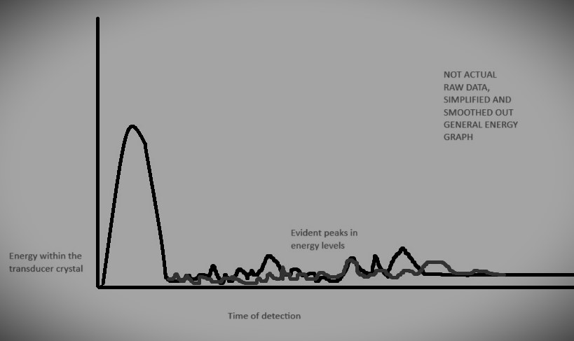
Essentially, to conduct further imaging and testing of the energy levels of the backscattered wave system would require the approximation of the reasoning for the current backscatter within the system. The reasoning behind the approximate and tested increase in wave energy within the each of the crystals is expected to be because of the resonation within the crystal deformation, and the production of the backscattered wave through diffuse scattering to harmonize, essentially producing a higher energy wave because of the added energy of the crystal from the electrical electrodes. Further reasoning as to the production of the ultrasound wave stimulating a larger amount of energy within the transducers that were not being activated in the production of the ultrasound wave is because the deformation of the crystals produced a larger surface area for the backscattered wave to be produced from, relative to the detective transducers. This was especially true within the case of the DreamCATCHER system, as the flat disc was the most capable of producing a larger relative surface area for the wave backscatter.
3.3.Safety Testing
The functionality analysis, or safety testing of the project is a relatively broad umbrella term used to describe the analysis of the safety, longevity, and actual potential for the system to function within clinical trials. This step of the project can only be completed after a prototype of the micro crystals and transducer are created, and is heavily reliant on the backscatter wave analysis portion of the testing, which is arguably the most important aspect of the testing, as if the device is not capable, within an acceptable margin of error, to detect either an individual deformation within the crystal, or several deformations under several different applied voltages, then the whole idea behind the concept is rendered impossible. If the backscatter wave analysis portion of the testing yields positive results, then this portion of the testing would consist mostly of simulating a living organism, and trying to determine the effect that may have on the micro crystal, and vice versa. This portion will analyze the potential longevity of both the micro crystal and the transducer within the body, as well as whether the micro crystal is prone to movement under similar conditions than that of neural tissues. This could be done using a plethora of different simulation techniques, but majority of the testing will be damage testing, simulating the natural environment by using things such as gelatinous substances, and liquids with similar chemical composition to that of the body's natural fluids. This portion of the testing will also consist of safety tests, such as the analysis of the dangers involved with the implantation of the set of devices, and the chemical analysis of the composition of the devices to determine whether or not they would react chemically within the body.
With the micro crystal, and the transducer system completed, as well as fully tested within the backscatter wave testing analysis portion of the project, the safety testing can commence. The safety testing will consist primarily of simulating the natural environment that the microcrystal will face inside of the human body. This, on paper, seems like a relatively simple task, you take material of similar gelatinous properties is that of neural tissues, specifically that of the brain, as it is the most vital aspect, or rather portion of the human body in which neural tissues reside, and the easiest to simulate, and you place the micro crystal inside of the gelatinous material for an extended period of time, and under some set condition. The gelatinous material, can be made out of almost anything, as long as in material properties, such as density, the ability of the material to move and be moved by certain objects, or rather forces, and the overall salinity and chemical composition in terms of acidity and baseness remains the same, the material will act as a relatively good example of the neural tissues inside of the brain. This may seem easy, but in actuality mimicking the chemical composition, and chemical nature of the elements of the brain are rather difficult, as the constant fluctuations in ion dense solution, and chemically dense solution as well as chemically dense areas within the brain, create a challenging and constantly fluctuating environment in which the micro crystal must reside. For this, as constantly simulating the fluctuation of chemical change within the brain will not only become labor intensive, but expensive and difficult as well as time consuming, a simpler more direct approach will be taken. A gelatinous substance composed out of some material, most likely some combination of gelatin, or other such thickeners, with another solution that closely resembles that of the brain. The most important factor in mimicking the chemical composition, and the factors of degradation within the brain of the micro crystal, would be the solution that the gelatin or other such thickeners mixed with. The crystal will be implanted in each of the separately made brains, of different chemical composition, and will be tested under these different environments. but this only accounts for the degradation of the micro crystal within the neural tissue. To best account and simulate the damage that the micro crystal, as well as the micro crystal implantation will have on the surrounding neural tissues, the most important aspect would be creating a gelatinous mixture that closest resembles that of tissues of the brain.
For testing in which the most important factor would be the analysis of the damage the micro crystal has on the neural tissue, the most important factor would be the appropriate simulation of the density and strength of the artificial simulation “brain” itself, so that it closest resembles that of the real neural tissue. This portion would analyze the potential damage that initial implantation, and long term implantation has on the surrounding neural tissues. For this, the crystal, or rather crystals, must first be implanted into our artificial simulation brain, after which, the area in which the needle penetrates the artificial brain will be analyzed macro and microscopically. The crystal, which would remain in the artificial brain, or rather one of, as several crystal bunches will be implanted into different brains of different chemical composition to analyze both the effect of the chemical composition on the micro crystal within biological tissue, but to see how this degradation can impact the damage the micro crystal causes. There will be a total of five brains, two of no particular chemical composition outside of the ordinary, besides the binding substance and the water it is mixed with, and three brains each of different chemical composition. The two “unflavoured” brains so to speak will act somewhat as controls, one, remaining stationary for a period of time, after which it will begin vigorous movement for another period of time, after which, this will be repeated again until another, longer duration of time. The second unflavoured brain will begin movement immediately after implantation, so the crystal has no time to naturally degrade, and this brain will remain in movement until the end of the experiment. All of the other, “flavoured” brains, will move in the same pattern as the first unflavoured brain, having periods of vigorous movement, and then none. Of course the brains will remain in a temperature controlled room, as to not allow the brains, composed out of some binder, to naturally fly apart. This type of testing will allow for the analysis of the brains, as well as the micro crystals inside of the brains, to determine whether or not conditions similar to that of neural tissues, specifically that of the human brain, will have any sort of negative effect on the longevity of the implanted micro crystal. This analysis will also allow for the understanding of the effects of the crystal on the surrounding tissue, and whether or not changes to either the delivery system, or the production of the crystal itself must be changed in order to accommodate living tissue.
With this being said, let us analyze the composition of the brain, and the type of environment we must simulate with our artificial brains, both flavoured and unflavoured, that is to say both the composition that the brains must take on, and the overall material properties in terms of density, and overall strength. The brain, overall, is maintained at a slightly basic pH level, ranging anywhere from 7.3 to 7.4 on the pH scale. Although this can vary in close proximity to ion channels, and the activation and excitation of the cell membranes, these effects are miniscule, and even on the microscale level can almost entirely be ignored. This information is crucial, as we can properly simulate the approximate pH level of the brain, to properly test the damage it may have on crystals implanted within it. The salinity of the brain is also incredibly important for this damage testing, but an overestimation of both the salinity, and the pH of the brain are needed, as the environment must be properly simulated in the harshest possible conditions. While the ordinary salinity of the brain ranges from 0.3 -0.4 %, we can increase those values to one or two percent, to create the harshest possible environment. Within the pH, while it will be increased to a certain degree above the normal within the testing, it will not be as significant. The density of the brain can be approximated as 1050 kg / m cubed, and this approximate density calculation is the most important aspect within the production of the simulation brains. By using a neutral binding agent that in no way will interact with the pH elevators, or the salt to increase the salinity of the brains, we can produce both flavoured and unflavoured brains without being concerned about the effects of the binder. The three flavoured brains will be one of extra high salinity, one of extra high pH, and one of a combination of the two factors in the average amounts, without elevation for compensation of the conditions within the brain.
With the knowledge of the composition of the brains, the artificial brains were produced, out of a neutral gelatin binder, and some amount of sodium hydroxide and salt mixed into the water before it was added to the binder. The brains were also poured into brain shaped moulds, not for any reason other than humour. When the brains were set, the testing of the crystals, and the implantation system could begin. For the damage testing of the crystal, a needle is penetrated several millimeters into the artificial brains, and the crystal is injected using saline solution. The surrounding damage is analyzed firstly, for damage that is present within the actual standard implantation methodology of the crystal. When this was done, the damage was minimal. While little quantitative descriptions of the damage caused by the implantation system can be used, the damage can only be described as minimal, leaving no apparent entrance wound if the needle used for implantation was thin enough. It is also important that the saline solution in which the crystal is delivered is not pumped at a high rate. If it is, sudden expansion and tearing is evident within the gelatinous substance, and as such, during implantation, the rate of the solution must be controlled. Otherwise, damage left by the implantation is minimal. After this was conducted, and the crystals were left in the brains, four of the brains were placed on specially designed vibrating plates, that vigorously shook the brains, to conduct the testing of the damage the crystals had on the brains, and the damage the brains had on the crystals. The brains placed on the testing plates were all of the flavoured brains, and one unflavoured brain, and the testing of this damage was conducted over an extended period of time, with the gelatinous unflavoured brain acting as a sort of control. None of the brains, even after extended vigorous movement for prolonged periods of time showed any real sign of degradation, and neither did the crystals. Both the brains and crystals remained in resemblance to their original shapes, after observation at the one day, two day, four day, and week long marks. The brains, besides showing some amount of degradation due to improper cooling showed no significant change in the area of the implanted crystals, and the crystals showed no significant change in size. A summation of all of the observations after periods of time can be seen in the table below, noting that the observations are somewhat averaged from each of the brains, with the fact that none of them showed significant change in either the brains, or the crystals implanted within them.
|
Period of time observation was made: |
Brain(s): |
Crystal(s); |
|
Day 0 |
The brains, while displaying some amount of degradation almost immediately after the start of the testing, do not display this degradation near the implanted site of the crystals. This is probably because of insufficient cooling near the brains, this issue will be addressed immediately by providing more cooling to the brains to prevent the melting of the binder. |
The implanted crystals remain within their implanted site, showing no signs of movement, shifting, or general degradation. |
|
Day 1 |
With the cooling issue fixed, and with the observations made, the brains again showed no signs of being damaged by the implanted crystals. This will probably be the case for the rest of the days of observation, as the crystals are simply too small and light to significantly impact anything with such high density, relatively. |
The implanted crystals remain within their implanted site, showing no signs of movement, shifting, or general degradation. |
|
Day 2 |
Regular observation of all of the brains proved that the crystals still had virtually no visible effect. Artificially simulating a more vigorous environment was done by increasing the speed of the motors responsible for the movement of the plates, and even then, the crystals appeared to have no effect. |
The implanted crystals remain within their implanted site, showing no signs of movement, shifting, or general degradation. The crystals remained in this state even after increased simulation of movement. |
|
Day 3 |
Regular observation of all of the brains proved that the crystals still had virtually no visible effect. |
The implanted crystals remain within their implanted site, showing no signs of movement, shifting, or general degradation. |
|
Day 4 |
Regular observation of all of the brains proved that the crystals still had virtually no visible effect. Artificially simulating a more vigorous environment was done by increasing the speed of the motors responsible for the movement of the plates, and even then, the crystals appeared to have no effect. |
The implanted crystals remain within their implanted site, showing no signs of movement, shifting, or general degradation.The crystals remained in this state even after increased simulation of movement. |
|
Day 5 |
Regular observation of all of the brains proved that the crystals still had virtually no visible effect. |
The implanted crystals remain within their implanted site, showing no signs of movement, shifting, or general degradation. |
|
Day 6 |
Regular observation of all of the brains proved that the crystals still had virtually no visible effect. And with the completion of the week-long testing, the crystals, as predicted, were too small and light to produce any amount of damage, beyond potentially the microscopic. Even the larger accidentally grown crystals were too light to do any sort of damage that could not be written off as negligible. |
The implanted crystals remain within their implanted site, showing no signs of movement, shifting, or general degradation. The crystals have remained within their implanted areas for an extended period of time, and even after fully stopping the testing to observe the damage done to the crystals and the surrounding area, little was discovered besides the miniscule initial wound of implantation. |
In summation, none of the crystals were in any way shifted from their original positions, and none of them, even after extended periods of time, in the order of several weeks, were changed beyond potentially the microscopic.
Analysis
4.Discussion
4.1.Analysis
The use of micro-scale piezoelectric crystals, and their subsequent backscatter when probed by an external transducer device, designed to be sitting on the external surface of the biological area of neural tissue measured, proved to be an incredibly simple, and reliable system for the detection of neural activity and activation. The crystals themselves, designed and produced using several different materials and methods of production, some of which being quartz, lead titanate, and lead zirconate titanate, and some of the production methodologies, such as growing the crystals in solution under constant irrigation, deposition or the materials of a complex patterned surface, and “powdering”, all proved to be relatively ineffective if not designed in incredibly small mesh system. They also proved most effective when contained within some containment loop, containing the small electrical components and travel paths to the crystal. The transducer device, based on the system of one central processing unit on the back of the device, with implanted informational wires also proved most effective is several of the arrays were focused on one area of the micro crystals at one time, while not being able to entirely, and with any sort of desired accuracy predict singular activation, primarily due to off timing within the system, the system was with a very reliable and high accuracy percentage able to detect the deformation of specific clumps of micro crystal sensors. The system also proved safe, and did not degrade within similar environments to that of neural tissues, specifically within the brain. The delivery system, and the crystals themselves also proved to be safe, and not damaging to the surrounding neural tissues, due to their light weight, and the comparatively high strength of the neural tissues. The system, overall, shows high promise within not only the concept, but the individual systems behind the project, and further testing, primarily of living tissue testing, must be conducted to further determine the systems ability to be used within medicine, or medical trials. Over all, when analyzing the ultrasound backscatter of a wave coming from an individual clump of crystals, it is most commonly expected, or rather viewed within the testing, that a larger portion of the array receives a larger portion of energy from the back scatter, compared to that of the normal. This is potentially due to the fact that under deformation, the crystal expands in several directions, causing a much more erratic and widespread distribution of its backscatter. While this may not be incredibly evident on the small scale, it creates a distribution of the wave, of both the wave of energy, as well as the wave distribution in space. as an initial seeking ultrasound wave hits a non deformed crystal, the wave is returned back through either Rayleigh scattering or regular ultrasound backstatter. In both cases this could be modeled as a spherical expansion of the wave from the point of backscatter, as was described by the mathematics examined in the wave analysis portion of this paper, and this energy could then be cataloged by individual ultrasound arrays. When the crystal became deformed however, the ultrasound backscatter became much more erratic, creating a much larger point of initial backscatter, then was evident within the non deformed crystal. This created a larger overall traveling sphere, allowing transducer arrays that were outside of the sphere of influence of the non deformed backscatter wave, to detect some amount of energy. By using the distribution of the energy within each transducer, it is also evident from which area of the brain,or rather neural tissue, the ultrasound backscatter deformation evidence came from.
4.2.Limitations
While primary and strongly contributing limitations and limiting factors behind all of the technology developed within this project are discussed in greater detail within their respective areas, this is a simple rundown of all of the limitations within the system as a whole, without delving into too much detail behind any of the technologies in particular.
Let us first start by discussing the general idea of the use of micro scale piezoelectric crystals in the detection of neural tissue as an idea and a potential stepping stone towards further research. The system has proved itself in not only the functional analysis of the system under several different types of conditions, but also within the safety testing of the system. The wave backscatter, while difficult to detect, is present in the deformation of the crystal, or rather is different enough under the deformation of the crystal to be detected by the ultrasound transducer, or transducer array, if the system is tuned specifically for the collection of the Rayleigh scattering from the crystal. The DreamCATCHER micro crystal system also proved overall very highly functional, as well as the Fuzzball system. While this is true, the systems do hold some amount of current limitations, primarily in their reliable production and implantation. The biggest drawback within the system as a whole, is the difficulty of creating the individual components of the system. In the case of the Fuzzball, production remains relatively simple, non labour intensive, and cheap, comparatively against other methods, but other, more glaring issues are present within this individual system. The outside metallic layer is prone to cracking, warping, deformation, and downright being removed from the piezoelectric material itself, due to the constant size fluctuation of the crystal, and the relatively low amount of bond created between the crystal and the metallic layer. The DreamCATCHER system on the other hand, while almost impossible to produce effectively, reliably, and cheaply, is much better in terms of functionality, due to the system's better engineered design. Within the crystal detection system of the greater BCI technology, limiting factors within the production of a reliable and effective system remains the difficulty of production within the system, and if these challenges can somehow be addressed, either through the development of higher precision tools and methodologies for the production of the micro scale materials, or through the development of better adhesive practices between the growth of non metallic and metallic materials, the technology could see great use within medicine, and very cheaply. Besides the actual detection sites, very little can otherwise be addressed within the transducer system, as the further precision and tuning of the system is reliant heavily on ultrasound, and the scaling down of the ultrasound system, which currently cannot be done due to material constraints, would require the production of a new material, or property for the creation and modulation of ultrasound waves. Besides this, the algorithm created for the sorting of the ultrasound waves and the detection of irregularities can also further be improved, by increasing the effectiveness of the sorting, and the irregularity detection algorithm. This doesn’t require any particular advancements within any particular field, but was rather not accomplished due to monetary, and time constraints.
4.3.Implications
The successful detection of variation within the piezoelectric deformation of the piezoelectric micro crystals is an incredible stepping stone towards the future of brain computer interfaces, and microtechnologies. The system is incredibly promising within several aspects. The primary aspect which shows incredible promise within the system, is the actual use of micro scale piezoelectric crystals within the detection of neural activity. As is shown by the previous testing, the deformation within the micro scale piezoelectric crystals, when producing an ultrasound backscatter wave from an initial wave, are distinct enough that we can accurately detect the activation of several clumps of neurons within the approximate location of the micro crystal. This is an incredible stepping stone into the future of neurobiology research, and the proper mapping out of the functionality of the brain. Not only this, but the technology also shows promise within ultrasound technologies, as well as the restoration of several lost functionalities due to damage to neural tissues, while not entirely explored, the possibility of using these micro crystals within future applications, different from detection, also show incredible promise. Overall the implications of this research, and of this technology as a whole, are incredibly positive, for several people. Researchers, people suffering from ailments due to damage to neurobiological tissue, and people wishing to make their lives Easier by incorporating advanced brain computer interface technologies into their daily lives. While further research is necessary for the complete overview of the technology, this research shows a solid outline for the production, testing, and interpretation of the technologies. Designs such as the Fuzzball, and the DreamCATCHER, all show promise within several regions of not only technologies, but also potential for commercialization. These technologies can of course be improved but as they stand they remain incredibly beneficial for several reasons, and incredibly promising.
Conclusion
5.Conclusion
The use of micro-scale piezoelectric crystals, and their subsequent backscatter when probed by an external transducer device, designed to be sitting on the external surface of the biological area of neural tissue measured, proved to be an incredibly simple, and reliable system for the detection of neural activity and activation. The crystals themselves, designed and produced using several different materials and methods of production, some of which being quartz, lead titanate, and lead zirconate titanate, and some of the production methodologies, such as growing the crystals in solution under constant irrigation, deposition or the materials of a complex patterned surface, and “powdering”, all proved to be relatively ineffective if not designed in incredibly small mesh system. They also proved most effective when contained within some containment loop, containing the small electrical components and travel paths to the crystal. The transducer device, based on the system of one central processing unit on the back of the device, with implanted informational wires also proved most effective is several of the arrays were focused on one area of the micro crystals at one time, while not being able to entirely, and with any sort of desired accuracy predict singular activation, primarily due to off timing within the system, the system was with a very reliable and high accuracy percentage able to detect the deformation of specific clumps of micro crystal sensors. The system also proved safe, and did not degrade within similar environments to that of neural tissues, specifically within the brain. The delivery system, and the crystals themselves also proved to be safe, and not damaging to the surrounding neural tissues, due to their light weight, and the comparatively high strength of the neural tissues. The system, overall, shows high promise within not only the concept, but the individual systems behind the project, and further testing, primarily of living tissue testing, must be conducted to further determine the systems ability to be used within medicine, or medical trials. It must be noted, that while the system shows incredible promise within several areas of the project, further research must also be conducted on several factors. The primary of which can be summarized as, can the system be scaled down further? How does the scaling of the system, the crystal, and the extended leads impact the detection of the system? How does further addition of crystals within a more concentrated area impact the accuracy of the system? What about the computational difficulty within analyzing all of the backscattered waves, and accurately detecting the change in the waves if not only the density of the amount of crystal within some area of neural tissue is increased but also if the amount of waves sent out per second to properly address the singular detection difficulties? All of these are questions that are yet to be answered or addressed in some way or another, be it with a more effective algorithm for the simplification of the detection of difference within the waves, or some better geometry for the crystals. All of these questions, and necessities for more advanced systems in one aspect of the project or another must at one point be addressed for the advancement of the system as a whole. But overall, the system, within its current state, exhibits exceptional properties, and potential.
Citations
[1]Shih JJ, Krusienski DJ, Wolpaw JR. Brain-computer interfaces in medicine. Mayo Clin Proc. 2012 Mar;87(3):268-79. doi: 10.1016/j.mayocp.2011.12.008. Epub 2012 Feb 10. PMID: 22325364; PMCID: PMC3497935.
[2]M. M. Moore, "Real-world applications for brain-computer interface technology," in IEEE Transactions on Neural Systems and Rehabilitation Engineering, vol. 11, no. 2, pp. 162-165, June 2003, doi: 10.1109/TNSRE.2003.814433.
[3]Sarah N. Abdulkaderv(2015, July 6). Brain computer interfacing: Applications and challenges. Egyptian Informatics Journal. https://www.sciencedirect.com/science/article/pii/S1110866515000237
[4]Salahuddin U, Gao PX. Signal Generation, Acquisition, and Processing in Brain Machine Interfaces: A Unified Review. Front Neurosci. 2021 Sep 13;15:728178. doi: 10.3389/fnins.2021.728178. PMID: 34588951; PMCID: PMC8475516.
Betancourt T, Brannon-Peppas L. Micro- and nanofabrication methods in nanotechnological medical and pharmaceutical devices. Int J Nanomedicine. 2006;1(4):483-95. doi: 10.2147/nano.2006.1.4.483. PMID: 17722281; PMCID: PMC2676643.
Pingale, Prashant & Kende, Prakash & Pardeshi, Krutika & Rajput, Amarjitsing. (2023). An emerging era in manufacturing of drug delivery systems: Nanofabrication techniques. Heliyon. 9. e14247. 10.1016/j.heliyon.2023.e14247.
Ganesamoorthy, S. & Sarguna, R. & Amaladass, Edward & Mani, Awadhesh & N. V., Chandra Shekar & Albert, Shaju & Palanimuthu, Vijayakumar & Manikandan, C. & Varadarajan, E. & Natarajan, Vigneshkumar. (2021). Large size piezo-electric single crystals for transducer applications.
Zheng, Hairong & Niu, Lili & Qiu, Weibao & Liang, Dong & Long, Xiaojing & Li, Guanglin & Liu, Zhiyuan & Meng, Long. (2023). The Emergence of Functional Ultrasound for Noninvasive Brain–Computer Interface. Research. 6. 10.34133/research.0200.
N. Weiskopf et al., "Principles of a brain-computer interface (BCI) based on real-time functional magnetic resonance imaging (fMRI)," in IEEE Transactions on Biomedical Engineering, vol. 51, no. 6, pp. 966-970, June 2004, doi: 10.1109/TBME.2004.827063.
Panwar, Ajay & Shangari, Jasdeep. (2022). CHEMICAL COMPOSITIONS AND ANALYSIS OF BIOCOMPATIBLE MATERIAL(S), TECHNOLOGICAL ADVANCEMENT AND STANCE. International Journal of Engineering Applied Sciences and Technology. 6. 1-10. 10.33564/IJEAST.2022.v06i12.001.
Saito, Yasuyoshi; Takao, Hisaaki; Tanil, Toshihiko; Nonoyama, Tatsuhiko; Takatori, Kazumasa; Homma, Takahiko; Nagaya, Toshiatsu; Nakamura, Masaya (2004-11-04). "Lead-free piezoceramics". Nature. 432 (7013): 81–87. Bibcode:2004Natur.432...84S. doi:10.1038/nature03028. PMID 15516921. S2CID 4352954.
Gurdal, Erkan A.; Ural, Seyit O.; Park, Hwi-Yeol; Nahm, Sahn; Uchino, Kenji (2011). "High Power (Na0.5K0.5)NbO3-Based Lead-Free Piezoelectric Transformer". Japanese Journal of Applied Physics. 50 (2): 027101. Bibcode:2011JaJAP..50b7101G. doi:10.1143/JJAP.50.027101. ISSN 0021-4922. S2CID 123625588.
Manbachi, A. & Cobbold, R.S.C. (2011). "Development and Application of Piezoelectric Materials for Ultrasound Generation and Detection". Ultrasound. 19 (4): 187–96. doi:10.1258/ult.2011.011027. S2CID 56655834.
Ma, Si Wei; Fan, You Jun; Li, Hua Yang; Su, Li; Wang, Zhong Lin; Zhu, Guang (2018-09-07). "Flexible Porous Polydimethylsiloxane/Lead Zirconate Titanate-Based Nanogenerator Enabled by the Dual Effect of Ferroelectricity and Piezoelectricity". ACS Applied Materials & Interfaces. 10 (39): 33105–33111. doi:10.1021/acsami.8b06696. ISSN 1944-8244. PMID 30191707. S2CID 52171041.
B. Toland; B. Houshmand; T. Itoh (1993). "Modeling of nonlinear active regions with the FDTD method". IEEE Microwave and Guided Wave Letters. 3 (9): 333–335. doi:10.1109/75.244870. S2CID 27549555.
Aoyagi, P.H.; Lee, J.F.; Mittra, R. (1993). "A hybrid Yee algorithm/scalar-wave equation approach". IEEE Transactions on Microwave Theory and Techniques. 41 (9): 1593–1600. Bibcode:1993ITMTT..41.1593A. doi:10.1109/22.245683.
V. A. Thomas; M. E. Jones; M. J. Piket-May; A. Taflove; E. Harrigan (1994). "The use of SPICE lumped circuits as sub-grid models for FDTD high-speed electronic circuit design" (PDF). IEEE Microwave and Guided Wave Letters. 4 (5): 141–143. doi:10.1109/75.289516. S2CID 32905331.
J. Berenger (1994). "A perfectly matched layer for the absorption of electromagnetic waves" (PDF). Journal of Computational Physics. 114 (2): 185–200. Bibcode:1994JCoPh.114..185B. doi:10.1006/jcph.1994.1159.
E.A. Navarro; C. Wu; P.Y. Chung; J. Litva (1994). "Application of PML superabsorbing boundary condition to non-orthogonal FDTD method". Electronics Letters. 30 (20): 1654–1656. Bibcode:1994ElL....30.1654N. doi:10.1049/el:19941139.
D. S. Katz; E. T. Thiele; A. Taflove (1994). "Validation and extension to three dimensions of the Berenger PML absorbing boundary condition for FDTD meshes" (PDF). IEEE Microwave and Guided Wave Letters. 4 (8): 268–270. doi:10.1109/75.311494. S2CID 10156811.
Giancoli, D. C. (2009) Physics for scientists & engineers with modern physics (4th ed.). Upper Saddle River, N.J.: Pearson Prentice Hall.
Anderson, John D. Jr. (January 2001) [1984], Fundamentals of Aerodynamics (3rd ed.), McGraw-Hill Science/Engineering/Math, ISBN 978-0-07-237335-6
M.J. Lighthill; G.B. Whitham (1955). "On kinematic waves. II. A theory of traffic flow on long crowded roads". Proceedings of the Royal Society of London. Series A. 229 (1178): 281–345. Bibcode:1955RSPSA.229..281L. CiteSeerX 10.1.1.205.4573. doi:10.1098/rspa.1955.0088. S2CID 18301080.
P.I. Richards (1956). "Shockwaves on the highway". Operations Research. 4 (1): 42–51. doi:10.1287/opre.4.1.42.
John Joseph Gilman (2003). Electronic basis of the strength of materials. Cambridge University Press. p. 57. ISBN 978-0-521-62005-5.
Donald D. Fitts (1999). Principles of quantum mechanics. Cambridge University Press. p. 17. ISBN 978-0-521-65841-6.
Chiang C. Mei (1989). The applied dynamics of ocean surface waves (2nd ed.). World Scientific. p. 47. ISBN 978-9971-5-0789-3.
Olver, P.J. (1995), Equivalence, Invariants and Symmetry, Cambridge Press.
Petrovskii, I. G. (1967), Partial Differential Equations, Philadelphia: W. B. Saunders Co..
Pinchover, Y. & Rubinstein, J. (2005), An Introduction to Partial Differential Equations, New York: Cambridge University Press, ISBN 0-521-84886-5.
Polyanin, A. D. (2002), Handbook of Linear Partial Differential Equations for Engineers and Scientists, Boca Raton: Chapman & Hall/CRC Press, ISBN 1-58488-299-9.
Polyanin, A. D. & Zaitsev, V. F. (2004), Handbook of Nonlinear Partial Differential Equations, Boca Raton: Chapman & Hall/CRC Press, ISBN 1-58488-355-3.
Polyanin, A. D.; Zaitsev, V. F. & Moussiaux, A. (2002), Handbook of First Order Partial Differential Equations, London: Taylor & Francis, ISBN 0-415-27267-X.
Roubíček, T. (2013), Nonlinear Partial Differential Equations with Applications (PDF), International Series of Numerical Mathematics, vol. 153 (2nd ed.), Basel, Boston, Berlin: Birkhäuser, doi:10.1007/978-3-0348-0513-1, ISBN 978-3-0348-0512-4, MR 3014456
Stephani, H. (1989), MacCallum, M. (ed.), Differential Equations: Their Solution Using Symmetries, Cambridge University Press.
Wazwaz, Abdul-Majid (2009). Partial Differential Equations and Solitary Waves Theory. Higher Education Press. ISBN 978-3-642-00251-9.
Wazwaz, Abdul-Majid (2002). Partial Differential Equations Methods and Applications. A.A. Balkema. ISBN 90-5809-369-7.
Zwillinger, D. (1997), Handbook of Differential Equations (3rd ed.), Boston: Academic Press, ISBN 0-12-784395-7.
Acknowledgement
I would like to thank many people who have helped me in the completion of this project, all of which were crucially important in its completion. Firstly, I would like to thank my parents, Elena and Maksim Tyurin who helped me not only mentally, push through the project, even when things seemed dim, and somewhat impossible, and for helping me acquire the proper materials, without both of which, I would have never been able to finish this project. I would also like to thank J.Sung, and C.Gray, my computer science and robotics teacher, as well as science fair coordinator, and my ELA teacher, respectively. J.Sung for allowing me the opportunity in participating in the CYSF, and for reading over initial drafts of my work, and providing suggestions and help when necessary. C.Gray for reading over my initial work, and encouraging me to pursue the project, and my interest in the sciences. Without both of these individuals influencing me I would have never been capable of completing the project, and I am gratefull to them greatly. I would again like to reiterate my eternal gratitude to all who helped me with this project in any capacity, and the appreciation I hold to every one of them. Thank you very much all! It wouldn’t have been possible without you!