
RobilityX - The Future of Mobility
Kimaya Satavalekar
Dr. E. P. Scarlett High School
Grade 10
Presentation
Problem
The problem being explored in this project is: "Can a tendon-driven hybrid continuum joint lift loads while maintaining flexibility?"
Our world is a rapidly developing technological hub, focused on increasing task efficiencies and improving the daily lives of individuals. As a result, our lifestyles are becoming increasingly inactive due to growing advances in technology, automation, and online development. In 2022, approximately 31% of adults globally (nearly 1.8 billion people) were unable to reach the recommended physical activity levels (World Health Organization, 2024). Subsequently, impairments in mobility are also rising. This is because increased levels of inactivity can further increase the chances of developing diseases such as cancer, heart disease, and diabetes.
Data from Statistics Canada demonstrates that around 7.2% of Canadians aged 15 or older faced mobility disabilities in 2012, which rose to 10.6% in 2022. This is evidence that mobility challenges are becoming more common over time, emphasizing the importance of solutions that support movement and assist individuals with a lack of mobility.
This issue is what inspired me to launch RobilityX, an early-stage startup focused on developing a new, innovative robotic mobility solution, centered around the growing need for mobility assistive technologies in the near future. RobilityX is currently a growing tech startup and a Y Combinator/Ingenious+ Spark Applicant. We are looking for funding to further develop our next-generation mobility technology.
However, the launch of RobilityX raised an important question for me: "How can we design effective, load-bearing robotic legs, capable of performing human-like motions?" While there are multiple designs of assistive exoskeletons, capable of transporting an individual across a distance, all of these technologies require the user to exert some level of lower-body strength during usage. For instance, companies such as Eksobionics and Lifewalk are designing assistive tech that supports the user's body, which can limit the effectiveness of the robot. RobilityX aims to eliminate majority of the bodily strength and load on the individual, allowing for more free movement. Most existing assistive systems rely on user strength because fully external robotic mobility (such as RobilityX) introduces challenges in power density, safety, and control. However, recent advances in actuators, sensors, and real-time control now make it very possible to explore this technology. RobilityX is approaching this project incrementally by validating each subsystem before attempting the full model.
That is why this project focuses on the design of one specific subsystem relating to continuum joints. We are designing a simple continuum joint system to test the range-of-motion and load-bearing capacities of continuum robots, through multiple iterations.
Method
All RobilityX progress is recorded daily on the RobilityX Instagram Account: https://www.instagram.com/robilityx/
This project focuses on the design of a ball-and-socket tendon continuum joint, which is a subsystem of the larger RobilityX prototype. Since the end goal is to be able to lift an entire human and be able to transport them across a distance, it is necessary to implement a fluid, adaptable motion to the robot. The ball and sockets allow for this tentacle-like movement.
Objective:
Currently, RobilityX is 1 month into the above timeline and has completed 2 successful prototypes: CD-01 and CJ-01.
0-3 months:
- Deciding which leg joints to use and choosing the functionality of those joints.
- Ensures that a single external leg segment is capable of lifting a predetermined mass repeatedly without failure.
- Closed loop balance test (using real-time feedback) on a fixed user rig.
- Demonstrates minimal user force contribution on a joint subsystem.
3-6 months:
- Prototype a two-legged system on a gantry/rig.
- Increase the load on each joint.
- Increase the surface area of the bottom leg support; testing different support systems (such as actuated claws).
- Make the system carry a passive dummy safely.
- Implement emergency fail-safe procedures.
- Consider safety and ethics procedures while constructing the robot and conducting tests.
6-12 months:
- Manufacture aluminum subsystems with increased strength and structural integrity.
- Develop appropriate spinal support systems that are used in accordance to the gantry/rig.
- Supervised lab demonstrations with safety harnesses and fail-safes.
- Create data showing stability and load transfer; this is used for future FDA approval.
Goal: The objective of this project is to design and evaluate different robotic actuator joints to develop the most flexible and structurally strong robotic legs possible within material constraints (3D-printed PLA).
Materials:
Tools:
- Bambu Lab A1 Mini 3D Printer
- Hot glue gun
- Hot glue sticks
Hardware/Software:
- 8 Channel PWM Servo Controller Hub
- 4 4.8V MG996R Servo Motors
- Fusion 360
- Bambu Lab Studio (Any Slicer)
- 5V 4A AC/DC adapter
Materials:
- JAYO PLA filament 1.75 mm
- 1 cm rubber straw
- 0.3 mm fishing line
Design Process:
CD-01 (Continuum Disc - Prototype 1):
This prototype is a simple design of a continuum joint system. It allowed me to gain a sense of understanding behind what continuum robots are and how to ensure good functionality and range of motion.
Continuum robots are extremely flexible, tentacle-like, soft-bodied robots that are capable of bending with more degrees of freedom than a typical rigid robot. They are mathematically modelled to have an infinite number of degrees of freedom (in theory), but in practice, they typically have a finite amount. While these joints do allow for lots of flexibility and dexterity, there is a tradeoff between flexibility and strength. Due to the lack of structural rigidity, it is more difficult for continuum joints to carry larger loads. Additionally, the increased flexibility of continuum robots leads to more complexity in setting the positioning and rotation of each motor. While most industrial-grade robotic joints have 1-2 DOFs (degrees of freedom), continuum joints can potentially have an infinite number of degrees of freedom.
Continuum robots are currently being used practically used in real-life scenarios such as surgical procedures and hazardous environments (Continuum Robotics Laboratory). However, these robots are in still early development stages and there is still much more to learn about them.
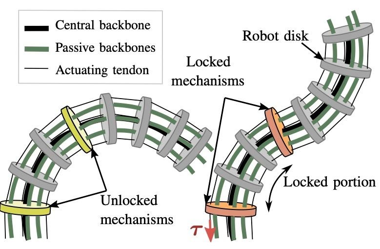 Figure 1 - A traditional continuum joint robot. This uses tendons that control the movements of each individual joints. The more joints there are, the more precise the robot can be, but it can also be harder to manipulate. Src- https://crl.utm.utoronto.ca/_pages/tdcr.html
For my initial CD-01 prototype, I decided to try and test a similar continuum joint system. Continuum joint systems typically have a flexible backbone that carries all the joints and keeps them arranged (shown in Fig. 1). For this prototype, I used a 1 cm rubber straw as the continuum backbone, because the rubber can be molded to fit any shape with minimal deformation. Then, I 3D printed individual disc mechanisms that have threaded fishing line through them, as shown in Fig. 2. These mechanisms ensure that the robot bends at certain "joints" of the robotic leg, acting as sections of the robot that can bend.
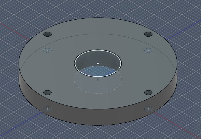 Figure 2 - The 3D model of the CD-01 Disc
At the bottom of the prototype, there is a 3D printed "control cross". Since CD-01 is a manually-actuated robot, this control cross is used to manipulate and pull/push each side of the robot to move the rest of the continuum joints. Generally speaking, most tendon-controlled robots use a string or rope to increase or release tension on specific sides or directions of a joint. By doing this, the joint is pulled (closed) or released (opened) back to a neutral state.
In this scenario, the fishing lines on each side of the cross begin in a neutral position with no tension on the joints. In robots, this neutral position is typically known as having "pre-tension." This means that the fishing line carrying the joints is not slack, but it isn't actively pulling to generate movement. When one side is pushed downwards, the tension on that fishing line increases, which pulls the string, and with it, the joints. At the same time, pushing one side down results in pushing the other up, which slackens the pre-tension on the fishing line of the other side. This continues to happen throughout the rest of the robot.
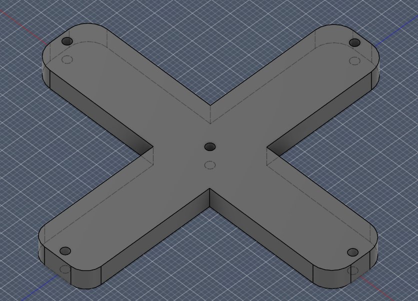 Figure 3 - The 3D model of the Control Cross of CD-01
CJ-01 (Continuum Joint - Prototype 1):
This prototype is the main prototype for this project. While CD-01 was purely a continuum joint, CJ-01 is a hybrid between purely rigid and continuum joints, finding a balance in between. To do that, we utilize ball-and-socket joints, which are joints you can commonly see in nature, such as inside a human's shoulder. Ball and socket joints have 3 DOFs. If there are enough ball and socket joints combined together, it is possible to mimic (while not entirely matching) the motion of a continuum joint. This means ball and socket joints have the capability to be flexible like continuum joints, while still remaining as rigid joints technically.
There are three different types of ball and socket joints that were iterated multiple times in this project: "Stiff Top Joints", "Medium Stiff Joints", and "Bottom Free Ball Joints." These corresponded to different locations of the robotic leg. In total, there are 6 ball and socket joints. The highest one is the "Stiff Top Joint", which is an anchoring joint that does not move, as shown in Fig. 4.
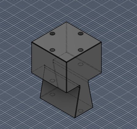 Figure 4 - "Stiff Top Joint" in CJ-01
This joint is there so that it can connect the rest of the joints to the rig that carries all of the motors. It also provides a baseline for where the rest of the robotic joints should be when they are at rest.
Additionally, there is also 1 Medium Stiff Joint that is connected directly to the Stiff Top Joint. This joint can be considered an "in-between" between the Stiff Top Joint and the Free Bottom Joint. This is because it is not a complete ball and socket joint.
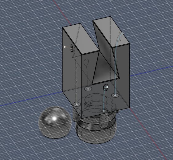 Figure 5 - "Medium Stiff Joint" in CJ-01
As you can see in Fig.5, there are no indents in the spherical section of the socket. This means that while the ball can still move, it doesn't have the capabilities to move a complete 180 degrees across 2 opposite sides of the socket. This mechanism was implemented to ensure that a tentacle-like curve could be achieved. If all of the joints are the same, then the robot can often lose its curvature.
Finally, the Bottom Free Ball Joints are used for complete freedom and movement that normal ball and socket joints have, as shown in Figure 6. Ultimately, the design of CJ-01 is based off of a telescopic design with increasing joint freedom and mobility as you move down the robot.
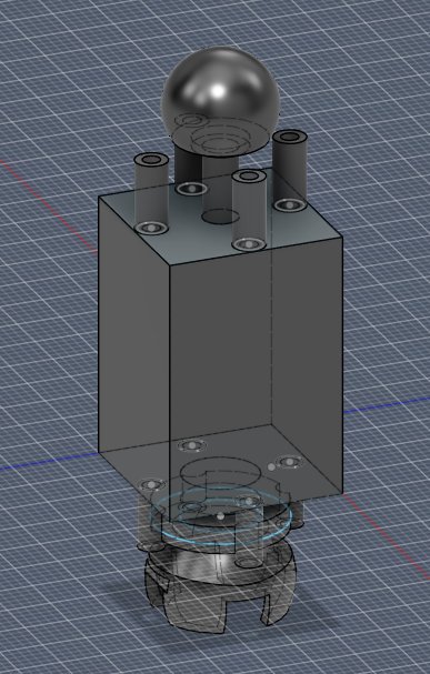 Figure 6 - "Bottom Free Ball Joints" in CJ-01
There were 3 major problems that I stumbled upon while developing the ball and socket joints:
- Thin walls and lack of strength - Since the ball and socket joints are very small, the thin walls of the socket portion are inadequate protection to hold and allow for enough space for a ball to move around. This means that often times, the socket portion of the joint would not print correctly, or it would break upon usage. Especially when an extra load was connected to the joint, it would not have the structural integrity to support it. Since the goal for this prototype was to make a compact and small design (space constraints), I was unable to increase the size of the socket walls for extra space. After lots of design and iteration, I added built-in supports that would hold together the wall.
- Tolerance - While 3D modelling parts that need to fit together perfectly, tolerance is an important factor that must be considered. I needed the ball to fit inside the socket loose enough that it could move around freely, but not too loose to slip out while doing work on a load. Additionally, due to the thin walls of the socket, it was difficult to also test tolerance because the socket would often snap while trying to fit the ball in. I tried to use lubricant multiple times, but it didn't seem to help.
- Alignment of the joints - After printing the first, working design of CJ-01, I realized that all of the joint sides were not aligned to the corresponding sides of the other joints. While actual continuum joints have passive backbones (refer to Figure 1) that directly connect each joint side respectively and guarantee joint alignment, CJ-01 does not have this, as proper flexible materials were not available. This resulted in random, uncontrolled joint movement, instead of smooth tentacle-like, controllable motion. To fix this, it was necessary to add some type of boundary for each fishing line's movement. I re-printed each ball-and-socket joint, but this time, I included 4 stabilized tubes extending outwards from each side (shown in Figure 5 & 6). Since the tubes were on every joint, they ensured that the joint sides stayed aligned together!
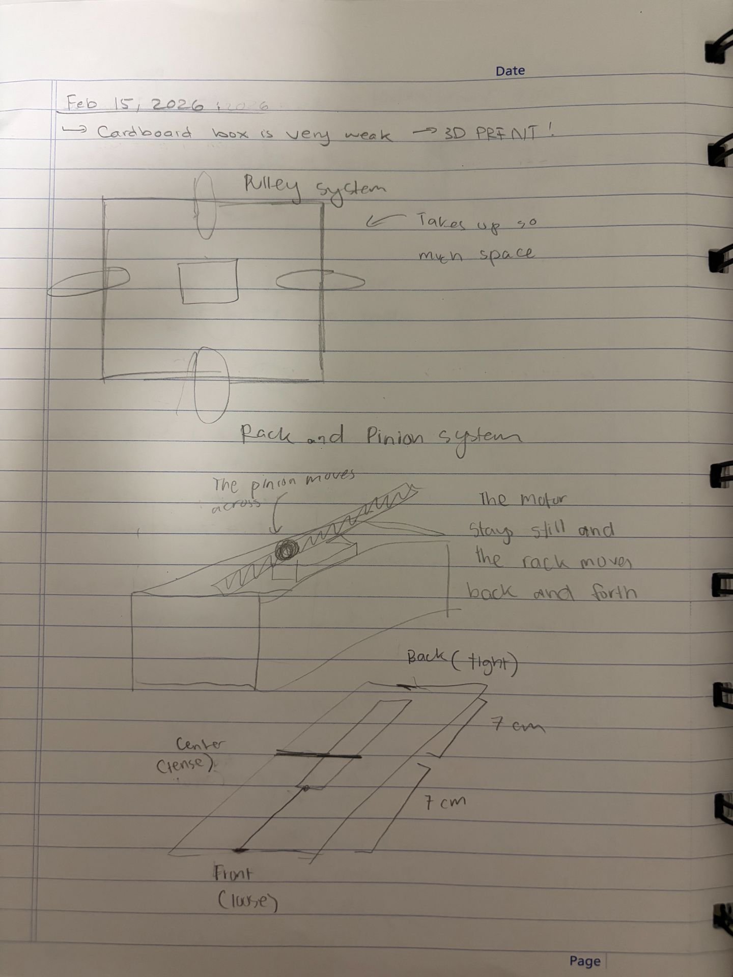 Figure 7 - Designs of different compact rigs for CJ-01
Making CJ-01 in a compact form was a challenge. Since there are 4 motors driving 4 individual pulley levers, a compact box design needed to be designed to make this possible. I did a lot of 3D printing and iteration to decide which design would be best. As you can see in Fig. 7, I looked at considered both pulley and rack-and-pinion systems, and I tried to figure out which would take up the least space while still maintaining effectiveness. Ultimately, I decided that a small compact box with a rectangular "pulley-like" connector would work.
Previously, I had designed the robot on a shoe box, which took up a lot of space, was unnecessarily heavy and was ineffective, as shown in Figure 8. As you can see, the pulleys in Fig. 8 were extremely wide and large, extending down into the shoe box. If I wanted to produce a compact rig, pulleys would not work. Instead, I took a cutout of a pulley, like a small rectangle (with the same diameter as the pulley). This did the same job necessary, but by utilizing less space.
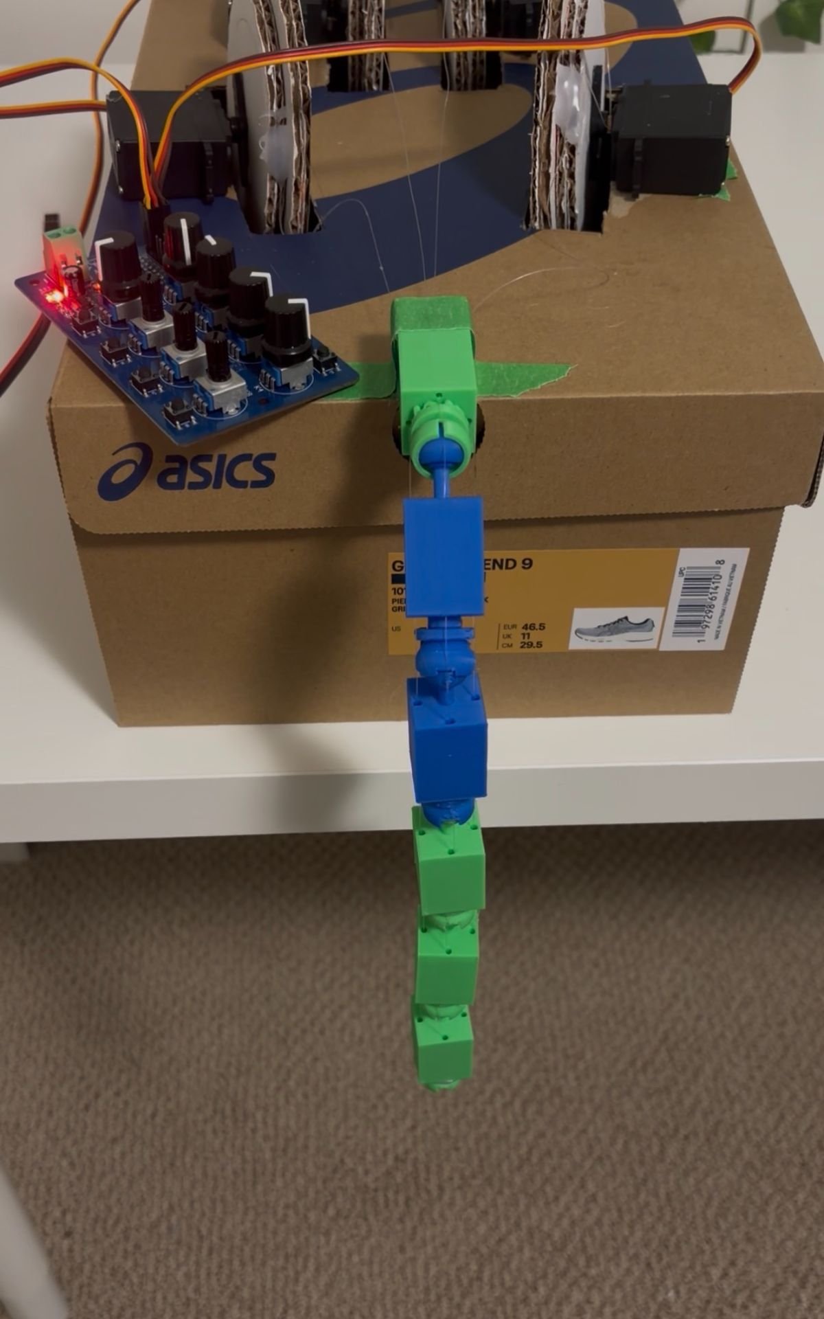 Figure 8 - Shoe Box CJ-01 (Before compacting)
When we look at the rectangular pulley that I used, a question arises. How do we determine the length of the pulley necessary. In this project, 90 degrees on the servo was required to be the neutral position on the robot, which refers to the pre-tension state. This means that moving a servo from 90 degrees to 180 degrees should move the robot from a completely open to a completely closed state. That meant that I needed to measure the distance required to pull the robot from an open to a closed state (which was 7 cm). Once that was done, I performed basic circumference calculations, knowing that 1/4 of my circumference was 7 cm, ultimately discovering the radius necessary for my rectangular pulley.
Each pulley would be connected to a line from one of the four sides of the robot. When the pulley moved, so would the fishing line. The model of the rectangular pulley is displayed in Fig. 9.
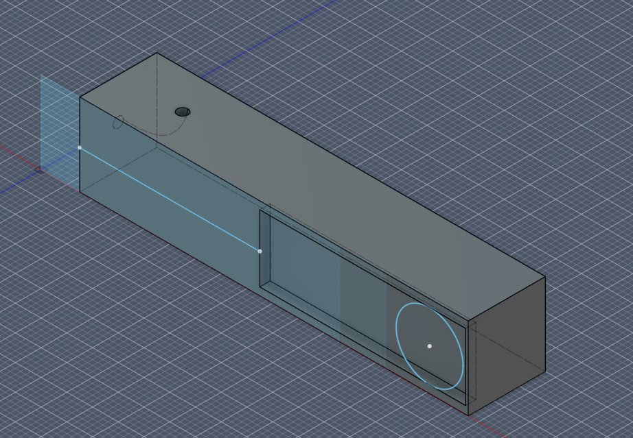 Figure 9 - Rectangular Pulley Cutout for CJ-01
Within the pulley and the rig, I had slight indentations to allow for the corresponding parts to sit in there. Below, Figure 10 shows how the final CJ-01 prototype looks. On the top, there is space for a PWM 8-channel servo control board, connected to 3D printed black handle that can be used to hold the rest of the robot. Then, on all 4 of the sides of the cube, there is a designated section for a servo motor to move each individual pulley lever, which is hot glued to its corresponding string. Finally, all of the 3D printed ball-and-socket joints are arranged in a vertically stacked pattern.
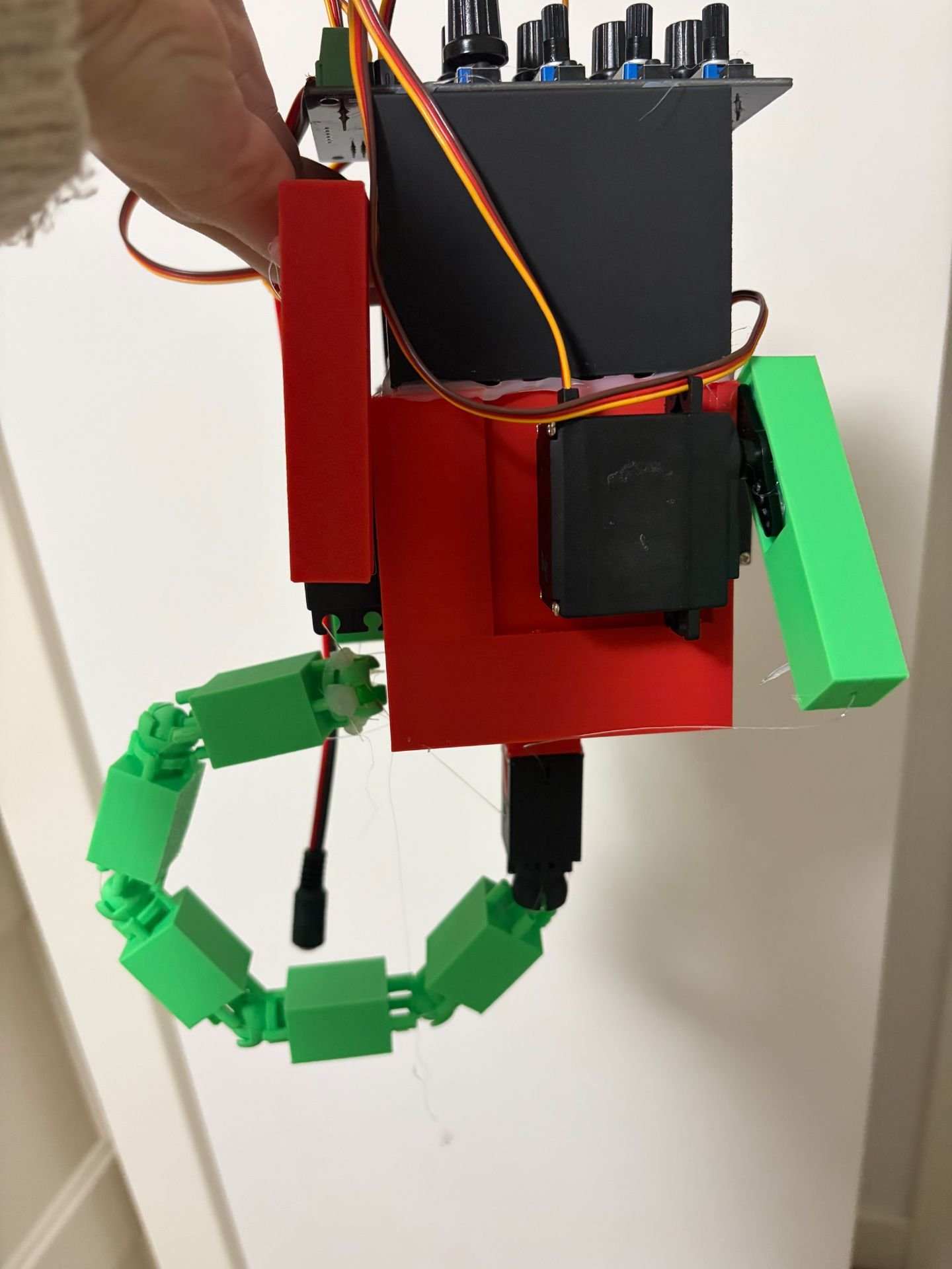 Figure 10 - CJ-01 Final Prototype
Servo Motors:
Servo motors (servos) are used in this project to move the robotic leg in each individual direction. Servo motors fall into the category of electric motors. Typically used in robotics, servos are used for precision, as they allow users to accurately control direction of rotation and degree of rotation. Figure 11 shows how an MG996R servo looks, which has a torque of approximately 9 kg/cm. This means it can lift approximately 9 kilograms approximately 1 centimeter from its center. This means that the farther away the weight is from the servo shaft, the less weight it can lift.
Servos fall into two categories: Continuous servos and positional servos. Continuous servos allow servo motors to rotate 360 degrees. Positional servos restrict movement to 180 degrees, typically through the usage of a pin to prevent rotation past 180 degrees. However, this project only utilizes positional servos.
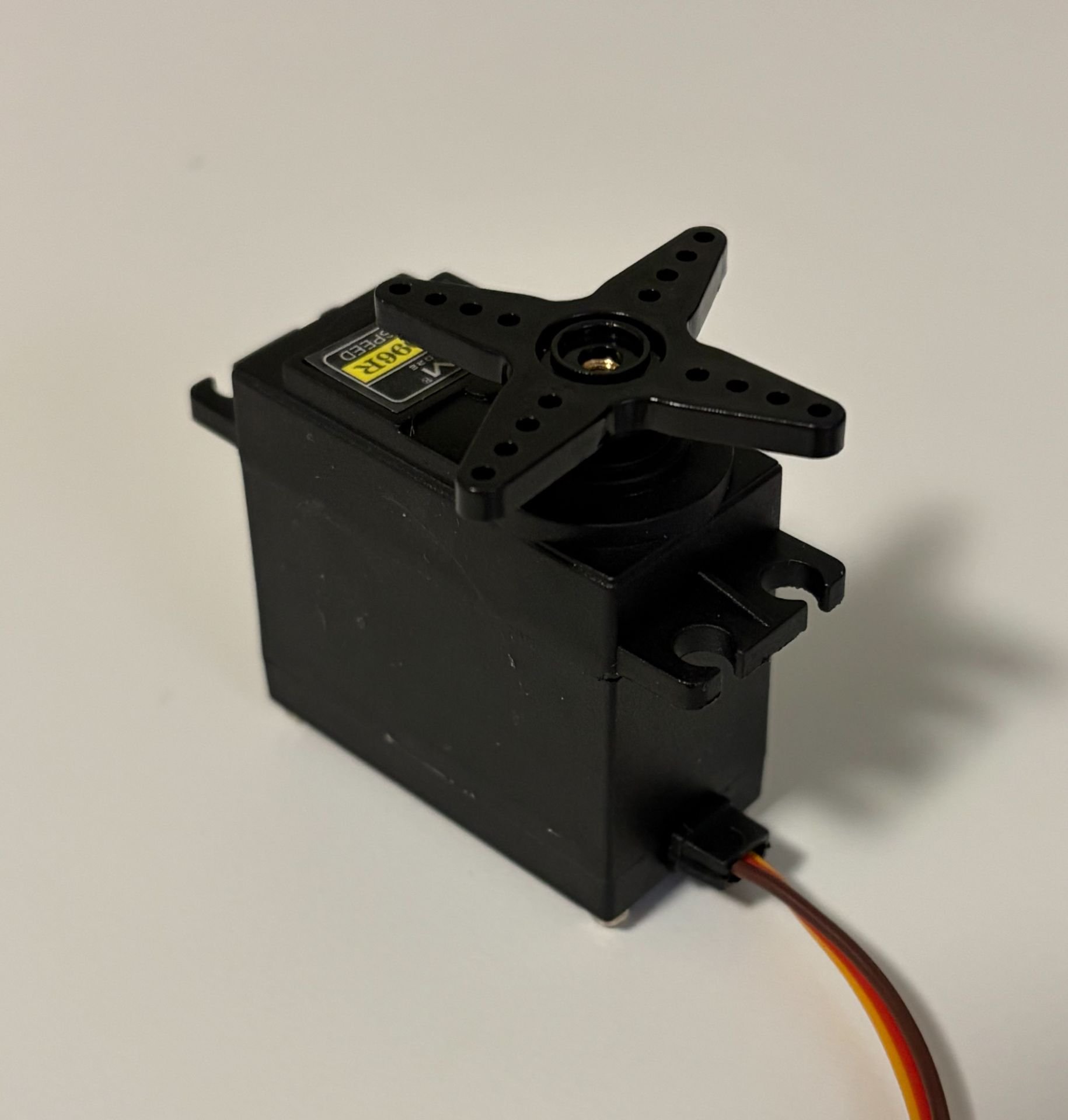
Figure 11 – Image of MG996R Servo Motor Servo motors rotate due to the fundamental concept of pulse width modulation (PWM). PWM is a type of digital signal. A digital signal is a type of processing signal that can be represented by two states only, often represented by a 0 or a 1 in binary. This can correspond to any two opposing values, such as “high” or “low,” or “on” or “off.” These are often compared to analog signals, which can have a wide range of potential values. A typical digital signal is shown in Figure 12. Often times, PWM is referred to as a digital signal that "acts" as an analog one, because it is capable of simulate analog power levels in components like servos. PWM is utilized by servos to change the duration of how long a DC signal is high (on) for.
The duration that a servo’s PWM signal is on for determines the direction of rotation for the motor, as well as the degree of rotation. A “pulse” defines the duration that a signal is high, or on for. Wider pulses tell the servo to move closer towards 180 degrees, while smaller pulses tell it to move towards 0 degrees. All servo motors have a neutral position, which is defined as the center of rotation. For positional servos, the center of rotation is 90 degrees.
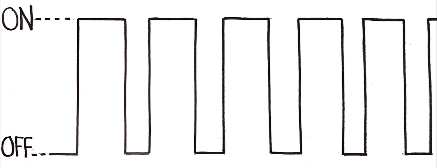 Figure 12 – Example of a DC signal
Additionally, a cycle refers to the total period when the pulse is high (on) and low (off). Most servo motors, such as MG996R servos have a frequency of 50 Hz, or 50 cycles per second. This means that each cycle is 20 milliseconds long. Within 20 milliseconds, the width of the pulse determines the angle the servo moves to. Figure 3.3 is a chart that represents the duration a cycle should be on and off for different angles (in an SG90 micro servo motor). 1 millisecond represents the minimum width of a pulse, and 2 milliseconds represents the maximum. Any value in between will move the servo motor to an angle in between 0 and 180 degrees.
Duty cycle is a measurement, in percentage, of the total time the signal is high in a full cycle. For instance, a pulse width of 2 milliseconds would have a duty cycle of 10%. This is because 2 milliseconds out of 20 milliseconds is 10% of the full cycle. In this case, 2 milliseconds would be the pulse width, or the time the cycle is high. 18 milliseconds would be the time that the signal is off.
| Position/Angle | Pulse Width (High/On) | Signal Duration (Low/Off) | Duty Cycle (%) |
|---|---|---|---|
| 0 degrees | 1.0 millisecond | 19.0 milliseconds | 5% |
| 90 degrees | 1.5 milliseconds | 18.5 milliseconds | 7.5% |
| 180 degrees | 2.0 milliseconds | 18.0 milliseconds | 10% |
Figure 3.3 – MG996R Servo Pulse Width Guide Servo motors have a variety of components that allow them to precisely rotate. All the primary components are shown in Figure 3.4 below: DC Motors - A crucial component of the servo motor is the DC motor. DC motors operate on the principal of electromagnetism, which is defined as the relationship between electricity and magnetism. DC motors harness DC current from a source, such as a battery and convert it into mechanical rotation. Once a DC input is taken, the electrical current passes through the rotating coil within the motor. This produces a rotating electromagnet, known as a rotor. A stationary field magnet (stator) is positioned around the rotor. Due to the attracting and repelling forces between the rotor and stator, mechanical energy is produced! In a servo motor, the DC motor performs the rotation.
Gear Train – The gear train is a chain of gears that are driven by the DC motor. The input gear starts off with a high speed but low torque. The output gear (final gear in train) has a low speed but high torque. Different sized servos have different torques, due to the varying voltages and gear trains.
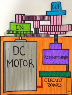 Figure 3.4 – Internal Components of a Servo Motor
For instance, an SG90 servo has a stall torque between 1.3 kg/cm to 1.5 kg/cm [7]. Kilograms per centimeter is the unit of measurement for torque. It represents how many kilograms of mass the servo can carry one centimeter away from the shaft.
Circuit Board - DC motors, when receiving voltage from a power source, instantly move. On the other hand, servo motors, when provided with a voltage, do not move. Servo motors will not operate without a microcontroller or control board providing a PWM signal, such as Arduino or Raspberry Pi. The circuit board is a principal component of the servo motor. It works by receiving the specific PWM signal from the microcontroller, and it converts it into an action to control the servo output. Typically, the circuit board ensures that the instructions passed down by the controller are conducted. A critical part of the circuit board is its feedback loop- a system in which the output is used to improve the input [8]. This allows for adaptation and minimal errors within the servo system. For instance, if the servo does not move to the right position, that position is sent back to the circuit board. Then the circuit board uses that output position to tell the motor where to move to reach the correct position.
In this project, we use an 8-channel servo controller board, which is the electronic component that provides each motor with the correct PWM signals to move to their positions.
Analysis
The purpose of this project is to develop the first step towards a robotic leg system that is capable of lifting large loads, such as a human, and transport them across a distance. However, many exoskeletons are capable of doing that right now, so what makes this project any different?
- Many current exoskeletons use structural architectures that can often limit adaptability to the human body. This makes it overwhelmingly difficult for disabled individuals to travel across a distance independently without a strain on their body.
- Most existing exoskeletons are rigid-jointed devices, which means that they have very limited number of degrees of freedom. This can result in a lack of human-like range of motion and mobilizing capabilities. This means that it is important to test the load-lifting capabilities of CJ-01.
CJ-01 Lifting Analysis:
| Mass Lifted (g) | CJ-01 Curvature/Bend (in %) |
|---|---|
| 10 | 100 (full) |
| 20 | 100 (full) |
| 30 | 80 |
| 50 | 50 |
| 60 | stall (unable to lift) |
This chart displays how CJ-01 performs while carrying different masses. Throughout 10-20 grams, it can completely lift and close. As it starts to reach 60 grams, it becomes more and more difficult to lift the robotic leg, and it ultimately stalls at 60 grams.
CJ-01 is able to lift a mass that is 50 grams heavy. However, the robot only closes to 50% of its max bending capacity. This means that after reaching 50% of the total lifting capacity, the robot servos stall, and the torque of the motors can no longer overcome gravity and the object's mass. As the curvature of the robotic leg increases, the mechanical advantage decreases while torque increases, resulting in the servo stalling. "Stalling" refers to the process in which a motor can no longer overcome the load that is on it and starts to stop or no longer move.
It is likely that a lot of torque was wasted through the friction created when fishing lines are moved, joints move, and and lever pulleys move, which can also contribute to the servo stalling.
Overall, considering the material and resource constraints that this project is under, it is challenging to further increase the quantity that CJ-01 can effectively lift. When picking between different joint types, there is typically a tradeoff between strength and flexibility/dexterity. Ball and socket joints typically are a balance in between the two, so it is expected that there is a slight loss in maximum strength and flexibility.
Conclusion
The objective of this project was to explore the capabilities and feasibility of a continuum-joint based system as the initial prototype for a robotic mobility leg, capable of transporting and lifting humans across a distance.
Testing of Prototype CJ-01 revealed that the robot was able to lift a 50g load, but was unable to lift it past 50% of total curvature/bending capacity. This likely occurred because of torque limitations in the MG996R servo motors. Additionally, more bending reduced the mechanical advantage while simultaneously increasing gravitational torque.
This project demonstrates a central and important tradeoff in robotics and engineering between strength (load capacity) and joint flexibility. Continuum soft-bodied robots are an emerging robotics technology that offers improved dexterity, adaptability, and flexibility, but it can also be extremely complex to use and control. On the other hand, rigid robots allow for more structural strength and stability, as well as easier control.
To conclude, this project tests and validates the use of continuum-based designs, not only in niche medical fields, but in mobility systems for individuals with disabilities. There were two prototypes designed throughout the course of the project and I faced some mechanical limitations that will be improved in future prototype iterations. The next steps I will take will be to increase load capacity while maintaining structural flexibility the most I can.
Citations
Boston Dynamics Atlas - https://www.youtube.com/watch?v=9e0SQn9uUlw
Dog Gaits - https://www.youtube.com/watch?v=WrR3fVQ3W3s
Tentacle style Spiral Arm - https://www.youtube.com/shorts/34aLAXHhT7k
Statistics Canada - https://www150.statcan.gc.ca/n1/pub/89-654-x/89-654-x2016005-eng.htm?
Statistics Canada - https://www150.statcan.gc.ca/n1/pub/11-627-m/11-627-m2024056-eng.htm?
Continuum Robotics Lab - https://crl.utm.utoronto.ca/
Tacuna Systems - https://tacunasystems.com/knowledge-base/continuum-robots-and-tactile-sensors/?srsltid=AfmBOopdP8hB5r5_5z6Pvn2PIML21py4IiVdlkvUONzTDNwlRtMMdSaD
Ekso Bionics - https://eksobionics.com/
Personal Links:
RobilityX Instagram Account: https://www.instagram.com/robilityx/
RobilityX Website (beta version): https://robilityx.wixsite.com/robilityx1
Credits to Autodesk for the usage of Fusion 360. I did all of my 3D modelling on Fusion. Credits to Bambu Lab for the A1 Mini and for Bambu Studio for slicing.
Acknowledgement
I am grateful to everyone that has supported me throughout this incredible journey of growth and learning.
Firstly, thank you to the Calgary Youth Science Fair for providing me with this brilliant opportunity to showcase my product, my learning, and most of all, my passion. Thank you so much to my family for standing by me and providing me with the electrical and software components necessary for the development of this device. Thank you to Dr. E.P. Scarlett and all of the teachers and staff for encouraging me, supporting me, and motivating me!
I have grown tremendously throughout the course of this project and I plan on continuing my work on it. I also appreciate everyone out there that is supporting my early stage startup, RobilityX, through Instagram.
I appreciate the endless encouragement that I was given. Once again, thank you to everyone!