Effect of Transmission Mechanism Type on Gripper Load Capacity
Tasneem Hossain
R. T. Alderman School
Grade 7
Presentation
No video provided
Hypothesis
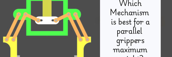
Testable Question: How do different transmission mechanisms affect the mechanical handling and maximum load capacity of a cardboard parallel gripper?
Hypothesis: If the transmission mechanism design is changed (transmission mechanisms: pin rack drive, Scotch yoke, belt-drive) then the maximum load held by the cardboard parallel gripper before fail or slippage will change, with the belt-driven mechanism likely holding the greatest weight, The main outcomes of the experiment is determined how the mechanism balances motion at all points from 360 servo. All mechanisms turn rotational motion into linear, so similarities arise in function. Under specific conditions, the gripper must apply enough pressure to counteract the object’s weight. Slippage occurs when the jaws can no longer maintain stable contact. The four-bar linkage keeps the jaws parallel, ensuring even pressure and reducing stress on the cardboard joints. The main differences in the transmission mechanisms, the pin/rack drive, Scotch yoke, and belt-driven mechanism, are motion smoothness, mechanical advantage, and stress distribution, can affect how much load the gripper can hold based on the material and design. Based on these design principles, the belt-driven mechanism is hypothesized to hold the highest load before slippage, because it provides smoother motion, minimizes binding, and distributes movement more evenly across the linkage compared to the other mechanisms.
Research
1. Parallel Grippers
What is parallel gripper? Parallel use two jaws that move side by side to grab, hold, and release objects smoothly The jaws move in sync, giving a stable grip without overcomplicating things. Fewer moving parts means fewer breakdowns. Parallel grippers usually have 2 fingers, but some 3 finger configurations are also out there. If it has 5 fingers, it’s most likely not a parallel gripper. Parallel grippers apply even pressure, making them ideal for jobs where slipping or uneven force would be a disaster. While angular and adaptive grippers overcomplicate things, parallel grippers keep it clean and reliable. Why must jaws stay parallel? the jaws of a parallel gripper do not rotate; the gripper jaws move in a linear fashion, also known as straight-line motion, while maintaining their parallelism. This gives parallel grippers the ideal capability of grasping parts of a uniform shape and size, such as cylinders, blocks, or machined parts.
2. Four-Bar Linkage
What a four-bar linkage is A four‑bar linkage is a mechanical system made of four rigid bars connected in a loop by pivot joints that lets motion transfer from one link to another in a controlled way.
How it keeps motion controlled Because the links are connected in a closed loop, moving one bar causes the others to move in a predictable path, controlling how the output motion (like opening claws) happens.
Why it is used in grippers It keeps the gripper jaws moving in coordinated motion (often parallel) so they grip objects evenly without twisting or tilting.
Effect on jaw alignment With a four‑bar setup, the jaws stay aligned (parallel or consistent relative orientation) as they open/close, which helps grip objects securely.
3. Force and Load
Definition of force Force is a push or a pull that can change an object’s motion or shape and is measured in newtons (N). What load capacity means Load capacity is how much weight or force a system can handle before it fails or slips. Relationship between force and weight Weight is the force of gravity acting on an object’s mass, greater mass means greater force due to gravity. How grip force affects slippage If the grip force isn’t high enough to counteract the weight (and friction) of the load, the object will slip out.
4. Friction
What friction is Friction is the force that resists motion between two surfaces in contact. How friction helps objects stay gripped Friction between the gripper and object prevents slipping, more friction means a more secure grip. Cardboard vs other materials Cardboard has a rough surface that can create more friction than smooth materials like plastic but less than rubber. Factors that increase/decrease friction Rougher surfaces, heavier normal force (push together), and texture increase friction lubrication, smoothness, and lower contact force reduce it.
5. Torque
Definition of torque Torque is the measure of how much a force causes an object to rotate about a pivot. How servo motors produce torque Servos produce torque by applying force at a distance from the pivot in the motor’s output shaft, turning it. How torque affects gripping strength More torque means the gripper can apply greater force to hold heavier loads before slipping. Distance from pivot and torque Torque increases with both force and the distance from the pivot point where the force is applied.
6. Servo Motors
What a servo motor is A servomotor is a motor with a feedback system that can precisely control angular position. Why servos are used in robotics Servos are used because they can move to and hold specific angles accurately, which is useful for grippers and robotic joints. How servos control angle and movement They use a feedback sensor and control signal to rotate the output shaft to a commanded angle and hold it. Limitations of servo strength Servos can stall or not provide enough torque if the load is too heavy or binding is high also they can overheat.
7. Arduino and Coding
What an Arduino is An Arduino is a small programmable microcontroller board used to control electronic components like servos. Role of coding in controlling servos Coding tells the Arduino what to do and when to do it. For servos, you write code that:
- includes a servo control library
- attaches the servo pin
- tells the servo what angle to move to
Why same code is used for fair testing Using the same code for all trials ensures that the only thing changing between tests is the mechanism type not how the servo moves. With identical servo movement patterns, the comparisons between mechanisms are fair and scientifically valid.
8. Mechanical Advantage
Definition of mechanical advantage Mechanical advantage is how much a machine multiplies the input force to do work on a load. How mechanisms change force and motion Mechanisms like linkages trade distance for force they can increase output force but decrease motion range Why some mechanisms hold more weight Mechanisms with higher mechanical advantage can convert small input forces into larger output forces, letting them hold heavier loads.
9. Mechanism Types: Bing videos are the exact model that will be used in the parallel gripper
Pin/rack drive — how it works A pin rack drive mechanism, commonly known as a rack and pinion system, converts rotational motion into linear motion through the interaction of a circular gear (the pinion) and a linear gear (the rack)
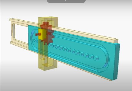 Diagram: YouTube user thang010146 (2012, September 17). Pin rack drive 2A. Microsoft Bing Videos or YouTube. Description rewrited.
The red gear acts as the input component. Its shaft end slides inside the track-shaped slot of the cyan pin rack. Due to the forces made by the gear engagement, both the cyan pin rack and the yellow slider, which carries the red gear, move in a reciprocating motion.
Rotational motion from a stationary power source like the servo is transmitted to the red gear using suitable mechanisms such as a double Hooke’s joint or an Oldham coupling.
Calculations
Diagram: YouTube user thang010146 (2012, September 17). Pin rack drive 2A. Microsoft Bing Videos or YouTube. Description rewrited.
The red gear acts as the input component. Its shaft end slides inside the track-shaped slot of the cyan pin rack. Due to the forces made by the gear engagement, both the cyan pin rack and the yellow slider, which carries the red gear, move in a reciprocating motion.
Rotational motion from a stationary power source like the servo is transmitted to the red gear using suitable mechanisms such as a double Hooke’s joint or an Oldham coupling.
Calculations
- Zr = Number of pins on the rack
- Zg = Number of teeth on the gear
- D = Diameter of the gear’s rolling circle
- T = Pitch between the gear and rack
- S = Stroke length of the rack
- L = Length of the groove on the rack
- N = Number of gear revolutions required to complete one working cycle (one double stroke of the rack)
- π = 3.142
Scotch yoke mechanism — how it works
The Scotch yoke mechanism is a mechanical device that converts rotational motion into linear motion, or vice versa, using a slotted yoke and a pin.
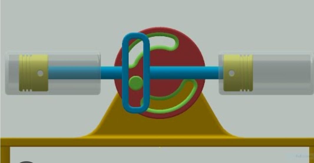 Diagram: Skyline Tutorials (2016\, January 6) How Scotch Yoke Mechanism Works! | Best 3D Animation. Microsoft Bing Videos or YouTube.
The crank (input shaft) acts as the input component. A crank pin mounted on the rotating crank engages with the straight slot of the yoke. As the crank rotates, the crank pin slides back and forth within the slot, forcing the yoke (slider) to move in a reciprocating motion along a straight guide.
Rotational motion from a stationary power source like a servo is transmitted directly to the crank through drive mechanisms. The rotation of the crank is therefore converted into linear reciprocating motion of the yoke.
Motion Calculations
Diagram: Skyline Tutorials (2016\, January 6) How Scotch Yoke Mechanism Works! | Best 3D Animation. Microsoft Bing Videos or YouTube.
The crank (input shaft) acts as the input component. A crank pin mounted on the rotating crank engages with the straight slot of the yoke. As the crank rotates, the crank pin slides back and forth within the slot, forcing the yoke (slider) to move in a reciprocating motion along a straight guide.
Rotational motion from a stationary power source like a servo is transmitted directly to the crank through drive mechanisms. The rotation of the crank is therefore converted into linear reciprocating motion of the yoke.
Motion Calculations
- R = Radius of the crank (distance from crank center to crank pin)
- D = Diameter of the crank circle
- S = Stroke length of the slider (yoke)
- θ = Angular position of the crank
- x = Linear displacement of the slider from the center position
- N = Number of crank revolutions required to complete one working cycle (one double stroke of the slider)
- π = 3.142
Belt pulley mechanism — how it works
In belt drives, power is transmitted between at least two pulleys by a belt. One pulley drives the belt (driving pulley) and the other pulley is driven by the belt (driven pulley). In belt drives, the speed is often reduced, so that in these cases the smaller of the two pulleys is the driving pulley.
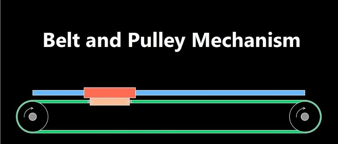 Diagram: XL Machines 120 (2021, December 31) Belt and Pulley Mechanism Animation for Rotary to Linear Motion. Microsoft Bing Videos or YouTube
The belt and pulley mechanism is used to convert rotary motion into linear motion. In this system, a belt is attached to a carriage at both ends, forming a closed loop that runs over two pulleys positioned at opposite ends.
One pulley acts as the driving pulley and is connected to an servo, while the pulley on the opposite side functions as an idler pulley, supporting and guiding the belt. When the driving pulley rotates, it moves the belt along its path. Since the carriage is fixed to the belt, the motion of the belt causes the carriage to move linearly along its guide.
The direction of the carriage movement depends on the direction of rotation of the driving pulley, allowing the carriage to move either forward or backward. To ensure reliable and slip-free motion transmission, timing (cogged) belts are often used instead of flat belts, and the pulleys are replaced with matching toothed pulleys.
This mechanism is widely used in automation systems, CNC machines, and positioning devices where controlled linear motion is required.
Motion Calculations
Diagram: XL Machines 120 (2021, December 31) Belt and Pulley Mechanism Animation for Rotary to Linear Motion. Microsoft Bing Videos or YouTube
The belt and pulley mechanism is used to convert rotary motion into linear motion. In this system, a belt is attached to a carriage at both ends, forming a closed loop that runs over two pulleys positioned at opposite ends.
One pulley acts as the driving pulley and is connected to an servo, while the pulley on the opposite side functions as an idler pulley, supporting and guiding the belt. When the driving pulley rotates, it moves the belt along its path. Since the carriage is fixed to the belt, the motion of the belt causes the carriage to move linearly along its guide.
The direction of the carriage movement depends on the direction of rotation of the driving pulley, allowing the carriage to move either forward or backward. To ensure reliable and slip-free motion transmission, timing (cogged) belts are often used instead of flat belts, and the pulleys are replaced with matching toothed pulleys.
This mechanism is widely used in automation systems, CNC machines, and positioning devices where controlled linear motion is required.
Motion Calculations
- Dp = Diameter of the driving pulley
- Rp = Radius of the driving pulley
- C = Circumference of the pulley
- S = Linear displacement of the carriage
- θ = Angular rotation of the pulley (in radians)
- N = Number of revolutions of the driving pulley
-
π = 3.142
Pros and cons of each
pin/rack drive:rotational to linear motion, simple, precise, limited range although) Scotch yoke:rotational to linear via slotted yoke simple, easy to prototype, but can bind cardboard) belt-driven:pulleys + belt rotational to linear, smooth, flexible, can adjust speed, belts may slip or stretch, need maintenance if steered off the gear Each has strengths in precision, durability, and load capacity.
10. Material Properties of Cardboard
Strength of cardboard Cardboard is strong in compression but weaker in tension and bending compared to metals or plastics.
Flexibility and deformation It bends more easily, which can help absorb forces but can deform under load if too weak. Limits of cardboard under load Cardboard will start to bend or collapse when the load exceeds its structural rigidity. Why cardboard is good for prototyping Cardboard is cheap, easy to cut, and quick to assemble, making it ideal for early design tests. Customized pieces, the original idea was to use lego, but lego may not have the specific pieces used for the primary mechanisms and make not fit into the rotations.
11. Engineering Design Process (iteration)
- Identify problem: Figure out what needs solving or improving
- Design & build: Create a prototype based on ideas
- Test & evaluate: Run experiments and collect data
- Improve design: Use results to make changes
- Repeat: Iterate steps until design meets requirements
Variables
Manipulated Variables: Primary joint/mechanism design connecting the servo to the four-bar linkage. Three types: pin/rack drive, Scotch yoke input, belt-driven input. Reason: This is what is being changed to see how it affects grip performance.
Responding Variables: Maximum load held before slippage, measured in grams of rice. Jaw alignment and deformation, recorded in observational notes Reason: These outcomes indicate which mechanism handles the object best.
Experimental Control Sample Why it is the baseline mechanism: The Pin/Rack Drive is the baseline mechanism because it serves as the standard point of comparison for the other two mechanisms (Scotch Yoke and Belt-Driven).
- All variables except the mechanism design are kept constant (same servo, Arduino code, claw design, four-bar linkage, and rice bag weights).
- The Pin/Rack Drive is tested first, and its performance in terms of maximum load held, jaw alignment, and deformation is recorded.
-
This performance provides a reference to see whether the other mechanisms improve or worsen performance under the same conditions.
Controlled Variables: Same servo motor and only using one * Why it should be controlled: The same servo ensures rotational motion is consistent across all mechanisms. A different servo could change torque, speed, or jaw movement, affecting grip performance. * How it was controlled: The same servo and only one servo was used for every trial and every mechanism.
Arduino control code * Why it should be controlled: The Arduino program controls the servo’s rotation angle and speed. Since all mechanisms change rotational motion into linear motion, the code should be the same for the servos output. * How it was controlled: The same Arduino code was uploaded and used for all mechanisms and trials.
Gripper material * Why it should be controlled: Different materials have different stiffness, friction, and strength, which could affect deformation and maximum load capacity. * How it was controlled: All gripper parts were made from cardboard for all mechanisms, and all mechanisms made out of cardboard as well. Claw design * Why it should be controlled: The size and shape of the claws affect the contact area and friction with the rice bags. * How it was controlled: All claws were cut from cardboard with identical size and shape.
Claw dimensions
* Why it should be controlled: Differences in dimensions could change grip performance.
* How it was controlled: All claws and 4 bar mechanism were the same length, width, and thickness.

Four-bar linkage lengths
* Why it should be controlled: Linkage length affects torque and jaw alignment. Changes could affect grip stability.
* How it was controlled: The same linkage lengths were used for all mechanisms.

Rice bag weight
* Why it should be controlled: Weight increases that does not match the required weights can produce unfair comparisons.
* How it was controlled: Weight was increased in equal steps for all trials and measured with a scale set at kilograms. This is the standard unit for the test.
Procedure
- Place a hot glue mat on the work surface to safely use hot glue while adjusting or reinforcing the cardboard gripper and mechanisms.
- Attach the cardboard gripper to the servo using the Pin/Rack Drive mechanism. Ensure the four-bar linkage is connected correctly.
- Verify that the Arduino code is uploaded and functioning by performing a test close of the gripper without a rice bag.
- Prepare the first rice bag, measuring exactly 0.2 kg.
- Place the rice bag between the gripper jaws.
- Activate the servo via Arduino to close the jaws on the rice bag, ensuring the jaws remain parallel and aligned.
- Repeat steps 4–6 with rice bags increasing in weight by 0.2 kg increments (0.4, 0.6, 0.8, 1.0, 1.2, 1.4, 1.6, 1.8, 2.0 kg) until the gripper slips or fails.
- Record the maximum load held before slippage or failure, along with jaw alignment and deformation, for the Pin/Rack Drive mechanism.
- Transition to the Scotch Yoke mechanism, keeping claws, servo, and Arduino code the same, and repeat steps 4–8.
- Transition to the Belt-Driven mechanism, keeping claws, servo, and Arduino code the same, and repeat steps 4–8. Include the LEGO belt wheel in the mechanism setup.
- After completing all trials, clean the work area, removing any loose cardboard or spilled rice to prevent hazards.
- Compare results between mechanisms, noting which mechanism holds the most weight, maintains jaw alignment, and resists cardboard deformation.
Observations
- Pin/Rack Drive:
- The gripper held rice bags up to 1.6 kg.
- At 1.8 kg, the rice bag slipped from the gripper, marking the failure point.
- Jaw alignment was generally parallel at lower loads but began to slightly misalign as the weight approached 1.8 kg.
- Minor cardboard bending was observed at the sliding pin and gear interface.
- Scotch Yoke:
- The rice bag was held securely up to 1.2 kg.
- Slippage occurred at 1.4 kg due to binding at the slot-pin interface.
- Jaw misalignment increased as the load increased, causing uneven gripping.
- Cardboard deformation became noticeable near the failure weight.
- Belt-Drive
- Jaw alignment remained parallel and stable across all tested loads.
- No slippage occurred within the tested range, the rice bag was held successfully at 2.0 kg.
- Little cardboard deformation was observed.
- The mechanism provided smooth, even motion, distributing forces effectively.
Trend Summary:
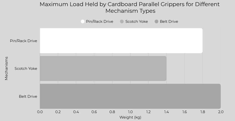
- The maximum load at which each gripper failed increased in the order: Scotch Yoke < Pin/Rack Drive < Belt-Driven.
- Jaw misalignment and cardboard deformation generally increased with the load for the Pin/Rack and Scotch Yoke mechanisms.
-
The Belt-Drive mechanism maintained alignment and stability throughout the testing range.
Analysis
The testing of the three transmission mechanisms showed measurable differences in maximum load capacity, jaw alignment, grip stability, and mechanical efficiency. Rice bags were added incrementally from 0.4 kg up to 2.0 kg until each mechanism could no longer hold the load. The Scotch Yoke held rice bags up to 1.4 kg, the Pin/Rack Drive up to 1.8 kg, and the Belt-Driven mechanism up to 2.0 kg. These results indicate that the type of primary mechanism affects a gripper’s ability to handle increasing loads. Scotch Yoke Mechanism: The Scotch Yoke mechanism had the lowest mechanical advantage effect on the gripper, and had the lowest load capacity, which can be contributed to its non-linear motion path. As the servo rotates, the rack connecting at the pin interface was measured inaccurately and made the rack move horizontally even with the backboard to keep it in place. The idea for the scotch yoke mechanism is to have the rack move vertically. The outcome was that the jaws experience uneven movement, leading to binding and uneven force distribution. This explains the earlier observations of slippage and cardboard stress under loads near its failing load. The mechanism is still simple and its design allowed rapid movement with little components, showing that simpler systems may be at advantage for low-force applications. The analysis shows that mechanical simplicity does not always translate to high load capacity when uniform force transfer is needed. Pin/Rack Drive Mechanism: Serving as the experimental control, the Pin/Rack Drive showed good performance due to its linear rack-and-pinion motion, which distributes force more evenly than the Scotch Yoke. This mechanism maintained better jaw alignment under increasing loads, reducing early slippage and deformation. However, its mechanical efficiency not so great. More input effort is needed to sometimes make the servo which is connected to the gear to match with the pins on the rack, as for the rack can move on its own speed because it has no supports to stop it. The results indicate that linear movement improves stability and load distribution, but efficiency and force-speed transmission are also limited by the mechanism’s design. This demonstrates that even mechanisms with consistent alignment can be limited if speed transfer is not equal to the linear component moving. Belt-Driven Mechanism: The Belt-Driven gripper consistently held the highest loads and maintained alignment across all rice bags. The belt provides uniform force along the entire jaw length, reducing stress in the cardboard that lead to deformation. This efficient force transfer made less rigid movement and was linear along each test. This was indicating a direct relationship between uniform force distribution and maximum load capacity. The mechanism’s stability under increasing loads confirms that design features promoting smooth motion and consistent contact improve performance. Overall, these results reveal a clear pattern: mechanisms that maintain jaw alignment, evenly distribute force, and convert input motion efficiently can hold higher loads and resist deformation. The differences between the three grippers highlight how mechanical design choices affect performance, with differences between simplicity and efficiency.
Conclusion
This experiment demonstrated that the transmission mechanism of a cardboard parallel gripper affects its maximum load capacity, jaw alignment, and deformation, confirming the hypothesis that changes in mechanism design alter performance. Among the three mechanisms tested, the Belt-Driven gripper held the highest load (2.0 kg) with minimal deformation and consistent jaw alignment, the Pin/Rack Drive held an second place load (1.8 kg), and the Scotch Yoke held the lowest load (1.4 kg) with more noticeable bending and misalignment through each place. The Pin/Rack Drive served as the experimental control, providing a baseline for comparison, its performance highlighted the improvements observed in the Belt-Driven system, which distributed forces more evenly across the four-bar linkage. minor variations in cardboard bending or jaw alignment may have resulted from slight problems in assembly or rice bag placement, showing procedural errors rather than errors in the experimental part. The results support the hypothesis because mechanisms with smoother motion and better force distribution maintained higher loads without failure, aligning with background research on torque, mechanical advantage, and friction in parallel grippers. Overall, the data shows that careful consideration of mechanism type, force distribution, and material properties can significantly improve gripper performance, and that reinforcement, pivot stabilization, and reduced friction could make better results without changing the basic design.
Application
Making the designs better and some insight on an improved project: Based on the observed performance of the three transmission mechanisms several improvements can be made. Reinforcing the cardboard structure: The main cardboard jaws and four-bar linkages could be reinforced using additional layers of cardboard or lightweight materials. This would reduce bending under load and allow the gripper to hold heavier rice bags without deformation. Optimizing the force distribution: Mechanisms such as the Scotch Yoke showed early jaw misalignment. Adjusting pivot points or adding small guide supports especially for components that are loose could improve parallel motion and maintain jaw alignment. Improving joint and linkage connections: The points where the mechanism connects to the four-bar linkage could be strengthened with small pins, maintaining even motion, particularly in the Scotch yoke mechanism, and allow higher loads to be handled. Reducing friction and binding in moving parts: For mechanisms prone to sticking or uneven motion, such as the Scotch Yoke, adding smoother pivot surfaces could reduce resistance, allowing the mechanism to operate more smoothly and grip heavier objects without failing or interlocking. Maintaining uniform load distribution across jaws: The Belt-Driven mechanism performed best because it distributed force evenly. Applying similar design principles, such as more balanced linkages or dual attachment points, could improve the performance of the other mechanisms without changing the overall parallel gripper structure or design of the transmissions. These design improvements are directly by the properties measured during testing: maximum load capacity indicates where structural reinforcement is needed, jaw alignment shows where motion must be stable and cardboard deformation highlights areas requiring stronger material support. Extension: Future investigations could explore the effects of alternative materials on the performance of parallel grippers, such as using lightweight plastics, thin metals, or reinforced cardboard to reduce deformation, and improve durability. The impact of scaling the gripper’s size could also be studied, as larger or smaller mechanisms may behave differently due to changes in torque, mechanical advantage, and friction. Other studies might test different servo motor strengths, two servo configurations, or changes in four-bar linkage geometry to better improve force distribution and maintain parallel jaw alignment under higher loads. Testing grippers on objects of different shapes, textures, and weights can show how mechanism design affects robotics across different real-world scenarios. The results of this experiment have applications in robotics, manufacturing, and automation, where parallel grippers are used to handle objects safely. Understanding how mechanism design, force distribution, and material properties influence performance can help engineers make more reliable and cost-effective robotic grippers, reduce material waste, and improve workplaces. This experiment may be a interest to hobbyists, teachers and students exploring low-cost prototypes, as they demonstrate how simple designs can be made for reliability. Future research could also test the long-term durability of different mechanisms under repeated use or continuous operation, giving to knowledge that can control maintenance schedules, design standards, and industrial practices for robotic grippers.
Sources Of Error
Several factors affected the results of this experiment. Because the gripper and mechanisms were constructed from cardboard, repeated loading caused bending, deformation, and gradual material wear, which influenced jaw alignment and grip stability. In the Pin/Rack Drive mechanism, bending at the sliding pin and gear interface reduced efficiency near the 1.8 kg failure point, while the Scotch Yoke mechanism experienced binding at the slot-pin interface, contributing to slippage at 1.4 kg. Mistakes in cutting accuracy, glue placement, and material thickness also affected structural strength and alignment. Friction differences between the cardboard surfaces of the gripper/claw and the rice bags can affect the performance, and variations in how the bags weight was distributed affected the exact point of slippage. The 360° servo motor applied torque differently across trials, slightly impacting load capacity. These factors affected the tests and performances between the three mechanisms, even though the claws, four-bar linkage, and servo code were identical for all tests.
Citations
Standard Bots. (2025, October 9). Parallel grippers: Best designs, uses, & industry insights. Standard Bots.https://standardbots.com/blog/parallel-gripper Wikipedia contributors. (n.d.). Four‑bar linkage. Wikipedia. https://en.wikipedia.org/wiki/Four-bar_linkage? Robotpark. (2013, April 22). Robotic mechanisms – Four bar linkages 51010. Robotpark Academy. https://www.robotpark.com/academy/robotic-mechanisms-four-bar-linkages/ Purdue SIGBots. (2023). Four‑bar lift. Purdue SIGBots Wiki. https://wiki.purduesigbots.com/hardware/lifts/four-bar? Wikipedia contributors. (n.d.). Force. Wikipedia.https://en.wikipedia.org/wiki/Force Quizlet. (n.d.). Systems in Action – Chapter 2: Getting to Work [Flashcards]. Quizlet. https://quizlet.com/ca/517398012/systems-in-action-chapter-2-getting-to-work-flash-cards/ Hamilton-Wentworth District School Board. (2023). Understanding mechanical advantage [PDF].https://hwdsbcommons.s3.amazonaws.com/wp-content/uploads/sites/664/2023/12/Understanding-Mechanical-Advantage-2023-ho.pdf? Wikipedia contributors. (n.d.). Servomotor. In Wikipedia, The Free Encyclopedia.https://en.wikipedia.org/wiki/Servomotor? Wikipedia contributors. (n.d.). Arduino. In Wikipedia, The Free Encyclopedia.https://en.wikipedia.org/wiki/Arduino? Wikipedia contributors. (n.d.). Mechanical advantage. In Wikipedia, The Free Encyclopedia.https://en.wikipedia.org/wiki/Mechanical_advantage? TeachEngineering. (n.d.). Engineering design process.https://www.teachengineering.org/populartopics/designprocess Wikipedia contributors. (n.d.). Rack and pinion. In Wikipedia, The Free Encyclopedia.https://en.wikipedia.org/wiki/Rack_and_pinion Wikipedia contributors. (n.d.). Scotch yoke. In Wikipedia, The Free Encyclopedia.https://en.wikipedia.org/wiki/Scotch_yoke Tec‑Science. (n.d.). Belt drive basics.https://www.tec-science.com/mechanical-power-transmission/belt-drive/basics/ Alloprof. (n.d.). Motion transformation systems.https://www.alloprof.qc.ca/en/students/vl/sciences/motion-transformation-systems-s1437? Science Buddies. (n.d.). Engineering design process steps.https://www.sciencebuddies.org/science-fair-projects/engineering- Automation.com. (n.d.). Gripper 101: What is a gripper?.https://www.automation.com/article/gripper-101-what-is-a-gripper? Beezbot. (n.d.). Types of grippers – Industrial robotic explained.https://www.beezbot.com/learn/types-of-grippers-industrial-robotic-explained/ GripShape. (n.d.). How does a parallel robot gripper work?.https://www.gripshape.com/resources/how-does-a-parallel-robot-gripper-work Dassault Systèmes. (n.d.). Four‑bar mechanism.https://3dswym.3dexperience.3ds.com/en/post/3dexperience-edu-students/four-bar-mechanism_p-7nAmSKTBmeifoQuOzfPA? The Engineering Toolbox. (n.d.). Friction coefficients.https://www.engineeringtoolbox.com/friction-coefficients-d_778.html Wikipedia contributors. (n.d.). Friction. In Wikipedia, The Free Encyclopedia.https://en.wikipedia.org/wiki/Friction Wikipedia contributors. (n.d.). Torque. In Wikipedia, The Free Encyclopedia.https://en.wikipedia.org/wiki/Torque Designs: thang010146 (2012, September 17). Pin rack drive 2A. Microsoft Bing Videos or YouTube. https://www.bing.com/videos/riverview/relatedvideo?q=+pin+rack+drive+2a&adlt=strict&mid=371196C4C2D8FC68B8ED371196C4C2D8FC68B8ED&FORM=VRDGAR Skyline Tutorials (2016\, January 6) How Scotch Yoke Mechanism Works! | Best 3D Animation. Microsoft Bing Videos or YouTube.https://www.bing.com/videos/riverview/relatedvideo?q=scotch+yoke+mechanism&adlt=strict&mid=202ACFD5F074E9DBFF13202ACFD5F074E9DBFF13&FORM=VRDGAR XL Machines 120 (2021, December 31) Belt and Pulley Mechanism Animation for Rotary to Linear Motion. Microsoft Bing Videos or YouTube. https://www.bing.com/videos/riverview/relatedvideo?q=belt+drive+mechanism+turning+rotational+motion+into+linear+motion&adlt=strict&mid=C8E1BF7FC1B4FCAAC26FC8E1BF7FC1B4FCAAC26F&FORM=VCGVRP XL Machines 120 (2021, September 24) Parallel Jaw Gripper with Linkage Mechanism Animation (Design and header image) https://www.bing.com/videos/riverview/relatedvideo?q=Parallel+Jaw+Gripper+with+Linkage+Mechanism+Animation&adlt=strict&mid=F8FB9942467F99ED21E7F8FB9942467F99ED21E7&FORM=VRDGAR Google AI Gemini was used to analyze information and used to answer questions for research. Each source it provided was fact checked, and I used my own words to summarize the information it provided. All credits to creators of the designs used.
Acknowledgement
I would like to thank my teachers for supporting me along the way, giving me guidance, support and words of encouragement. I also want to thank my friends for cheering me on and offering helpful ideas. Your enthusiasm made this journey even more enjoyable! - Tasneem