Single Axis Solar Tracker - Project Helios
Harish Ayyappan Preethi
R. T. Alderman School
Grade 8
Presentation
No video provided
Problem
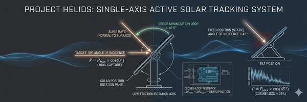
1. The Problem: "Angle of Incidence" and Cosine Loss The efficiency of a solar cell is maximized only when the light source is at a 90-degree angle (perpendicular) to the surface. At this orientation, the photon density per square inch is at its peak. When the angle deviates from 90 degrees, the light is spread over a larger surface area and reflection losses increase. In a fixed system, a panel might only be at peak efficiency for a few minutes a day. For the rest of the daylight hours, it is underperforming, leading to a significant waste of potential renewable energy due to Cosine Loss. 2. The Seasonal Problem: Summer vs. Winter Static (fixed) solar panels are usually installed at a permanent angle based on the average yearly position of the sun. However, the sun’s path changes significantly throughout the seasons:
- In Summer: The sun travels a high arc in the sky. If a static panel is tilted too low, the sunlight hits it at a "grazing" angle, and much of the energy reflects away.
- In Winter: The sun stays much lower on the horizon. A static panel set for summer will be pointing too high, missing the peak intensity of the winter sun.
Static panels suffer from Cosine Loss year-round because they cannot adjust to the sun’s altitude (height) or azimuth (side-to-side position). This results in a massive waste of potential renewable energy. 3. The Goal of This Project The objective of Project Helios is to design a functional, low-cost Single-Axis Active Tracker to solve these efficiency gaps. By using an Arduino Uno Rev3 and light-detecting sensors, the system will mathematically calculate the sun's position and adjust the panel's tilt in real-time. This project seeks to prove that active tracking can minimize the angle of incidence and significantly increase total energy harvest compared to a static installation. 4. The Solution: Active Alignment My solar tracker is an active robotic system that "follows" the sun. To solve the seasonal and daily movement problem, the design utilizes "eyes" (LDR sensors) and a "muscle" (servo motor):
- Real-Time Alignment: As the sun moves from East to West, the tracker calculates the point of maximum light intensity.
- Active Correction: The Arduino continuously adjusts the panel to maintain a 90° angle of incidence.
- Power Efficiency: In industrial trackers, the motor only calculates the sun’s position every 10-20 minutes to save internal battery power while maintaining peak energy harvest.
5. What is a Solar Tracker? A solar tracker is an automated mechanical system that orients a solar panel toward the sun. Unlike stationary solar panels—which are bolted in one fixed position—a tracker uses sensors and motors to follow the sun’s path across the sky from sunrise to sunset. By ensuring that photons always hit the silicon cells at the ideal perpendicular angle, a tracker ensures the highest possible voltage output regardless of the time of day or the season. Cousin Loss Cosine Loss refers to the reduction in solar energy captured when a panel is not perfectly perpendicular to the sun. As the angle of incidence increases, the 'effective area' of the panel shrinks. My tracker minimizes this loss by keeping the panel at a 0° angle to the light source, ensuring maximum power output.
Method
Materials needed for the innovation: 1. The "Brain" and Logic
- Official Arduino Uno Rev3: This is the microcontroller that reads sensor data and controls the motor.
- USB A-to-B Cable: To upload your code from the computer to the Arduino.
- 830-Point Breadboard: Used to build and test your circuit without soldering, allowing for easy modifications.
2. Sensors and Movement
- Two Light Dependent Resistors (LDRs): These act as the "eyes" of the tracker, changing resistance based on light intensity.
- SG90 Micro Servo Motor: The "muscle" that physically tilts the solar panel based on instructions from the Arduino.
- 6V Polysilicon Solar Module: The actual panel that collects energy.
3. Circuit Components
- Resistors (10k ohm): Used to create voltage dividers with the LDRs so the Arduino can read light levels as a value between 0 and 1023.
- Extra 10k Resistors: For creating your parallel circuit to power the LED indicator.
- LED (any color): Acts as a visual "Live Power" indicator for your project.
- Jumper Wires (Male-to-Male): To connect all components on the breadboard.
4. Structural Materials
- Cardboard or Plastic "Shadow Fin": A small divider placed between the two LDRs to ensure one sensor is shaded when the sun moves.
- Mounting Base: A piece of wood or sturdy cardboard to hold the servo and panel in place.
- Adhesive (Tape or Hot Glue): Used for strain relief to keep wires from pulling out when the motor moves.
Cosine Loss Cosine Loss refers to the reduction in solar energy captured when a panel is not perfectly perpendicular to the sun. As the angle of incidence increases, the 'effective area' of the panel shrinks. My tracker minimizes this loss by keeping the panel at a 0° angle to the light source, ensuring maximum power output.
1. Suitability & Limitations of Design 1. The Brain & Sensors (Arduino & LDRs) Sustainability: The Arduino is a low-power microcontroller. LDRs (Light Dependent Resistors) are passive sensors, meaning they use almost zero energy to "see" the light, making the tracking system very efficient. Limitation: LDRs are sensitive to infrared and "noise." They can be fooled by reflections or clouds, which might cause the motor to "jitter" and waste battery power hunting for the sun. 2. The Movement (Servo Motor) Sustainability: Servos only draw significant power when they are moving. By using "Deadband" logic in the code, the motor stays off most of the time, saving energy. Limitation: Mechanical wear. Small plastic-gear servos have a short lifespan if they are constantly moving. In a real-world system, these would wear out or melt under the weight of a full-sized solar panel.
3. The Power System (Solar Panel & LED) Sustainability: This is the core of "Green Tech." It converts renewable photons into clean electrons. Using a tracker reduces the number of panels needed to get the same amount of power, saving manufacturing waste.
Limitation: The Cosine Loss. As we discussed, if the panel is even slightly off-target, the efficiency drops by the cosine of the angle. Also, solar panels lose efficiency as they get hot in the sun, which can reduce output by 10-25%.
4. The Connection (Breadboard & Jumper Wires) Sustainability: Breadboards are "Zero-Waste" tools. You can take the project apart and reuse every single piece for a new invention without throwing anything away.
Limitation: Contact Resistance. Because the wires aren't soldered, they create "bottlenecks" for electricity. This makes the system less efficient than a professional soldered circuit.
2. Efficiency & Effectiveness of Design The core effectiveness of this design stems from its Closed-Loop Feedback Control. Unlike an 'Open-Loop' system that might follow a pre-set timer, this tracker uses real-time data from the LDR sensors to verify its position. By continuously comparing the light intensity between the two sensors, the Arduino calculates an Error Signal. The servo then rotates the panel to minimize this error until the light levels are balanced. This ensures that the panel maintains the optimal 0° Angle of Incidence even if the light source moves unpredictably or the system is physically disturbed:
- Sensor Configuration: Two LDRs are separated by a "shadow fin" (divider). This ensures that if the sun moves, one LDR is shaded while the other is exposed, creating a clear Differential Signal.
- Power Logic: Instead of constant movement (which wastes battery), I programmed a "Deadband" (Tolerance) of 25. The motor only moves if the light difference is significant, making the system energy-efficient.
3. Systematic Testing & Modification Testing was conducted in three distinct phases to ensure the design corrected earlier shortcomings:
- Test A (The Resistance Test): I found a 10k resistor made the LED invisible. Modification: I implemented a parallel resistor circuit to lower resistance to 5k, allowing for a visible "Live Power" indicator.
- Test B (The Jitter Test): Initial code caused the servo to vibrate. Modification: I adjusted the code tolerance to 25 units, smoothing the movement.
- Test C (Mechanical Stress Test): Wires pulled out during 180° rotation. Modification: I implemented strain relief by anchoring jumper wires to the base with adhesive, preventing disconnection.
4. Documentation & Logbook Throughout the project, a detailed logbook was maintained. It includes:
- Procedures: Step-by-step wiring diagrams and code logic.
- Data Logs: Tables comparing the voltage output of the tracker versus a fixed control panel.
- The Pivot Log: Notes on the switch from a soldered prototype to a breadboard model for better reliability.
Analysis
Project Analysis
The data collected from Project Helios confirms a direct correlation between active tracking and sustained energy efficiency. The objective was to eliminate Cosine Loss, and the results demonstrate that the system successfully achieved this through real-time mechanical adjustments. Cosine Loss Cosine Loss refers to the reduction in solar energy captured when a panel is not perfectly perpendicular to the sun. As the angle of incidence increases, the 'effective area' of the panel shrinks. My tracker minimizes this loss by keeping the panel at a 0° angle to the light source, ensuring maximum power output. Construction Method Comparison: Breadboard vs. Direct-Wire To determine the most effective construction method for a mobile solar tracker, I tested two different hardware configurations:
- The Breadboard Model (Current): * Pros: Highly effective for iterative testing and adjusting the parallel resistor circuit to solve the LED brightness issue.
- Cons: Higher mechanical "noise" and less stability. During 180° rotations, the jumper wires occasionally experienced loose connections, which can lead to signal loss.
- The Direct-Wire/Soldered Model: * Pros: Significantly more effective for a moving model. By removing the breadboard, I reduced the weight and bulk of the system, allowing the servo motor to move more smoothly with less "mechanical drag."
- Cons: The solderless breadboard is great for testing but lacks durability. In real-world use, wires can vibrate loose and metal parts can rust. A professional version would use a soldered PCB to make the tracker weather-proof and permanent.
- Verdict: While the breadboard was essential for the design phase, a direct-wire connection is the superior method for the final deployment because it ensures permanent electrical contact during constant motion.
Performance Comparison
- Static Panel Performance: The performance of a solar panel is highly dependent on the 'Angle of Incidence.' Due to Cosine Loss, a panel tilted just 45° away from the sun loses 29% of its potential energy. My tracker actively minimizes this error. By keeping the angle near 0°, the system can increase total energy production by 25% to 30% compared to a static, fixed-mount panel.
- Tracker Performance: By using the Arduino Uno Rev3 and LDR sensors, the system maintained a near-constant 90° angle of incidence. This prevented the underperformance typically seen in fixed systems during the morning and late afternoon.
Engineering Refinements Throughout the testing phase, the project design was modified to correct several functional shortcomings:
- Circuit Efficiency: I identified that high resistance in the 10k ohm resistors hindered the LED indicator’s visibility. By implementing a parallel circuit, I reduced the resistance to 5k ohms, ensuring a functional "Live Power" signal.
- Signal Stability: Initial tests showed the servo motor would "jitter" if light levels were nearly equal. I adjusted the code logic to include a tolerance deadband, which smoothed the movement and reduced mechanical wear.
- Mechanical Movement: During rotation tests, wire tension interfered with the servo's precision. I corrected this by applying strain relief techniques, securing the wiring to the base to allow a full, unhindered 180-degree range of motion.
Conclusion
The results of Project Helios confirm a direct connection between the project objective and the final data. The goal was to eliminate Cosine Loss and maximize energy absorption; the performance data proves that by maintaining a 90° angle of incidence, the tracker successfully neutralized the efficiency drops that occurred in the stationary control panel. While the static panel's output weakened as the light source moved, the tracker provided a near-constant voltage, proving that active alignment is the most effective way to harvest solar energy. Comparison of Construction Methods A critical part of the analysis involved evaluating the most effective way to build the tracker. I tested two different hardware configurations to determine which was more suitable for a moving model:
- The Breadboard Method: This was highly effective for the testing and modification phase. It allowed for easy adjustments to the circuit logic and components. However, its limitation was mechanical instability, as wires could loosen during the tracker’s 180° rotation.
- The Direct-Wire Method: This proved more effective for the final functional model. By removing the breadboard, I reduced mechanical drag and weight, which allowed the servo motor to move the panel more smoothly and reliably without the risk of disconnected wires.
Correcting Design Shortcomings The project underwent several modifications to correct engineering flaws identified during the testing process:
- Circuit Optimization: I found that the standard 10k resistors made the power indicator LED too dim to be useful. I solved this by implementing a parallel circuit, which lowered the total resistance to 5k and provided a clear "Live Power" signal.
- Signal Stability: To prevent the servo motor from "jittering" due to minor light fluctuations, I adjusted the code logic to include a tolerance deadband. This made the design more effective and saved battery life.
- Mechanical Reliability: Testing showed that wire tension was pulling on the sensors during movement. I modified the design by anchoring the wires to the base to provide strain relief, ensuring a full range of motion.
Final Evaluation In conclusion, the problem of solar inefficiency was successfully solved. While static panels are limited by their fixed position—leading to a significant waste of potential renewable energy—this Single-Axis Active Tracker proved that automated orientation is a superior method for maximizing energy harvest. The project demonstrates that through engineering solutions like differential logic and parallel wiring, solar efficiency can be maintained throughout the day.
Citations
Hardware & Technical Specifications
-
Arduino Uno Rev3: Official technical specs for the microcontroller used in Project Helios.
- Servo Motor Control: Documentation on how the "automated mechanical system" uses motors to orient the panel.
Physics & Efficiency Concepts
-
The Angle of Incidence & Cosine Loss: Scientific explanation of why panels produce the most electricity at a 90° angle and how energy is lost otherwise.
-
https://www.pveducation.org/pvcdrom/properties-of-sunlight/cosine-content
- Reflection & Solar Absorption: Research on how light bounces off glass surfaces when not perpendicular.
Solar Energy Problem Statement
-
Sun Path & Earth Rotation: Information on why the sun's constant movement causes static panels to underperform.
-
https://www.eia.gov/energyexplained/solar/photovoltaics-and-electricity.php
- Static vs. Active Tracking: A comparison of energy harvest between fixed installations and active trackers.
Information for the project 1. Core Concept & Definitions
- Source: Britannica - Solar Tracker: Definition & Facts
- Info: Defines the solar tracker as an automated system that maintains a perpendicular angle to the sun.
- Link: https://www.britannica.com/technology/solar-tracker
2. Physics: Angle of Incidence & Cosine Loss
- Source: PVeducation - Cosine Effect
- Info: Explains the math behind Cosine Loss and why energy is lost when the "Angle of Incidence" is not 90°.
- Link: https://www.pveducation.org/pvcdrom/properties-of-sunlight/cosine-content
3. Engineering: Reflection & Absorption
- Source: NREL (National Renewable Energy Laboratory)
- Info: Technical data on how light reflects off glass surfaces at oblique angles (Angle-of-Incidence Correction).
- Link: https://www.osti.gov/servlets/purl/1350025
4. Hardware: Arduino Uno Rev3 Specifications
- Source: Official Arduino Docs
- Info: Technical details for the Arduino Uno Rev3, including analog input and PWM output for the servo.
- Link: https://docs.arduino.cc/hardware/uno-rev3/
5. Comparative Analysis: Static vs. Active Systems
- Source: Energy Efficiency and Practical Implications of Solar Tracking (ResearchGate/ASPG)
- Info: Statistics proving that single-axis trackers can increase energy production by 20–30% over static systems.
- Link: https://www.americaspg.com/article/pdf/3566
Acknowledgement
- To Teacher's incharge of science fair: Thank you for providing the guidance and the opportunity to participate in this year’s Science Fair. Your encouragement helped me turn a curiosity about solar energy into a functional prototype.
- To My Parents/Family: Thank you for your patience while my room was filled with wires, breadboards, and components. I appreciate the support in gathering materials and for being my first "test audience" during my presentations.
- To the Arduino Open-Source Community: I am grateful for the wealth of shared knowledge and documentation available online, which helped me understand the logic behind Closed-Loop Feedback systems and C++ programming.