How Does the Thickness of a Black Line Impacts A Line Following Robot’s Response?
Grade 6
Presentation
Hypothesis
My hypothesis is if a line detecting robot is tested for its accuracy when following a line, the robot will not be able to follow the line if the line it is too thick or too thin. This is because IR sensors may see either all white or all black and robot will not know what to do.
Research
What is an Infrared (IR) Sensor?
-
Infrared technology is used in many applications in our daily lives. Some examples include remote controls, sensor on garage doors, automatic doors at the malls, etc.
-
Infrared radiation was discovered in 1800 by an astronomer named, William Herschel.
-
Infrared light has a wavelength longer than visible light, making it invisible to the human eye.
-
Anything that gives off heat radiation, emits infrared radiation.
-
IR sensors are electrical devices that can recognize when something is in front of the sensor.
There are two types of sensors:
-
Active IR Senor
-
Passive IR Sensor
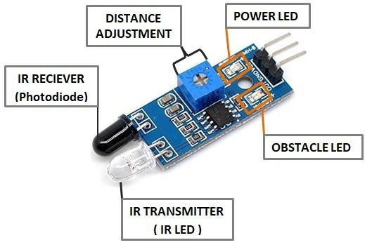
What is an Active IR Sensor?
-
An Active IR sensor releases and detects infrared radiation.
-
These sensors have followng key parts:
- Power LED
- Obstacle LED
- Distance Adjustment
- IR Transimitter (IR LED)
- IR Receiver (Photodiode)
-
These parts are shown in figure below.
How do IR Sensors Work?
-
An IR Transmitter sends an infrared light towards an object which cannot be seen with the naked eye. The light strikes an object and reflects. The receiver/photodiode picks up a single which is used by Arduino and processed.
History of Arduino
-
In 2005, Massimo Banzi and David Cuartielles created Arduino.
-
Arduino is an inexpensive electronic motherboard for students and professionals to create robots using sensors, motors, servos, etc.
-
They are many types of Arduinos such as: Arduino Uno R3, Arduino Nano, Arduino Micro, Arduino Leonardo, Arduino Mega 2560 Rev3.
-
In this project Arduino Uno R3 was used because it is affordable, and it can to be used for many small to large projects.
Variables
Independent Variables:
-
Robot Car
-
C++ Code for Arduino
-
Distance Between IR sensors
Dependent Variables:
-
Thickness of black line
Responding Variables:
-
Time for robot to complete three laps around the track
Uncontrolled Variables:
-
Battery Life
Procedure
-
Before starting the project, we need to order the material. All material was purchased from Amazon. A complete list of a material with Amazon description for each part is shown in the presentation attached in "Attachement Section". Once all the material is available, follow the following procedure.
-
Assemble the robot car kit purchased from Amazon. Follow the instructions from manufacturer.
-
Mount the Arduino Uno R3 to the robot chassis near the back end.
-
Mount the L298N motor driver to the robot chassis near the front end.
-
Mount three IR sensors equal distance apart at the front of the chassis. For my experiment the sensors are approximately 40 mm apart. When steps 2 to 5 are done, the robot should look something like images below.
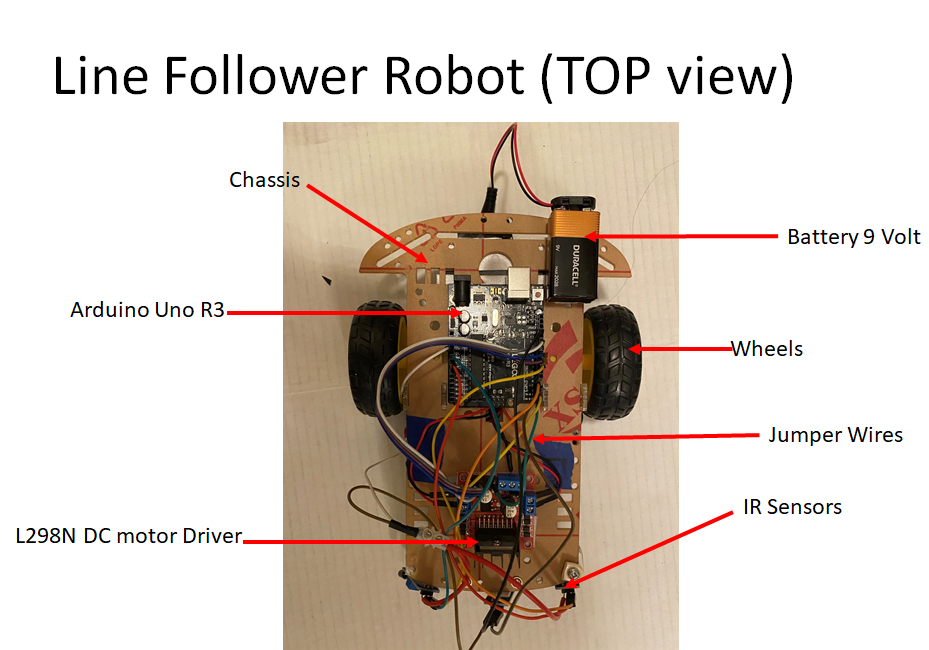
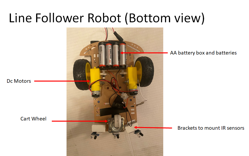
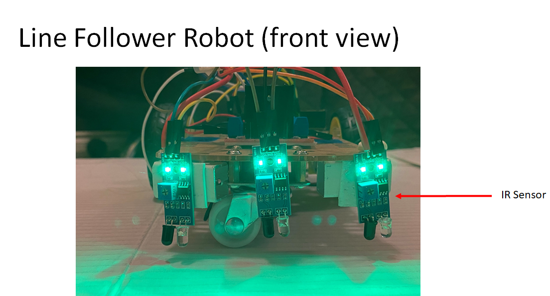
-
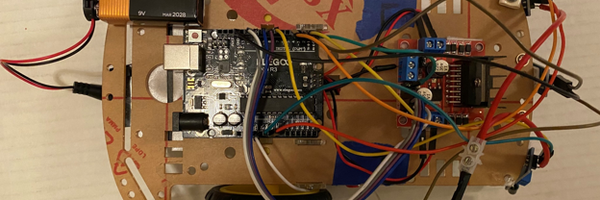
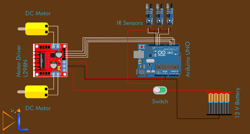
Wire the sensors, motor driver and Arduino Uno R3 (see presentation or figure below).
-
Install Arduino IDE software from Arduino’s website (https://www.arduino.cc/en/software).
-
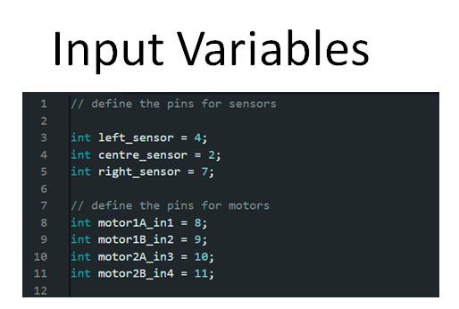
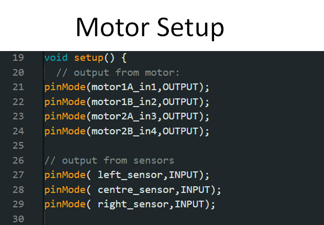
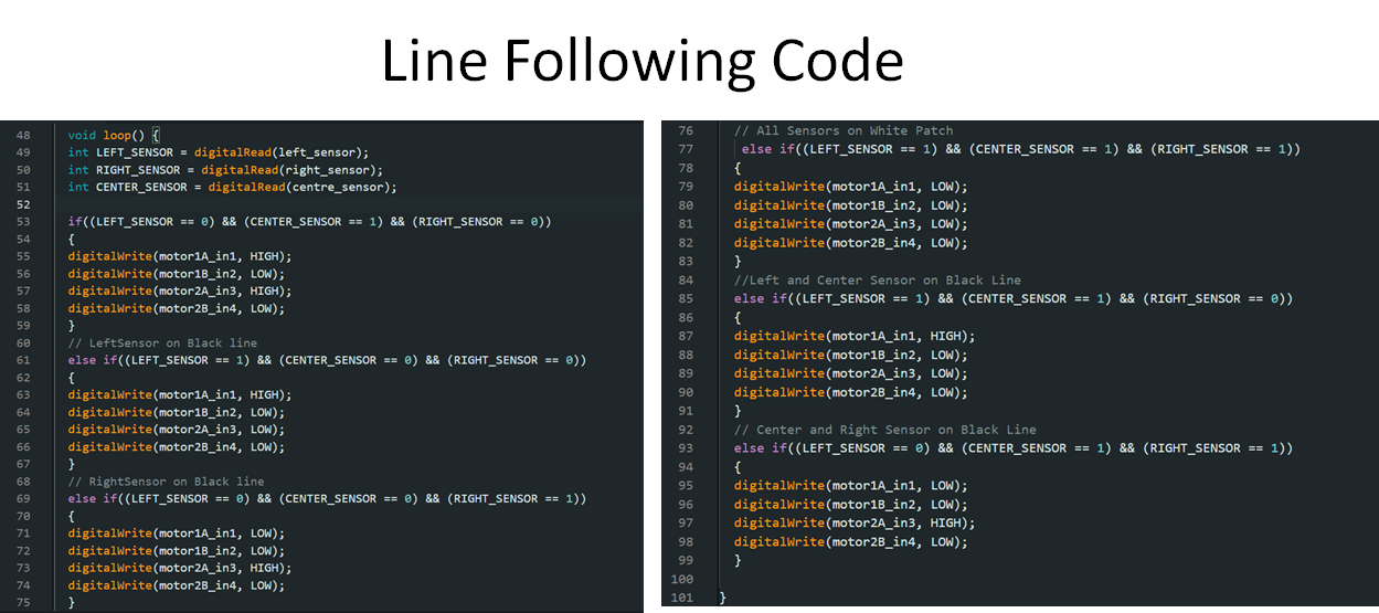
Using the installed software, write a C++ program for the robot. See Figure below.
-
Upload the program to Arduino Uno board using the upload wire.
-
Cut 12 white strips that will be placed around the black board to make a track. These 12 strips will be moved around to get different widths for the black track. You can start with 1.0” width track first and move the white strips out by 0.5” or you can start with 3.0” width track and move the strips inside by 0.5”. For my experiment I started with 3.0” and reduced it to 1.0”.
-
Draw a start line on the track.
-
Place the robot on the track. Start the timer when robot crosses the start line and stop it the timer when it completes three laps. You can use video recorder and record the video. These videos can be used to get start and end time. Screen shot from 3.0" track is shown below.

-
Repeat this 2 more times. For each track width, run it two more times to reduce error.
-
Change the track width by bringing the white strips 0.5” closer to get new width. Repeat steps 11 and 12 for new width.
-
Repeat steps 11 to 13 until track width of 1.0”.
-
Summarize the results.
Observations
How the robot works is using three IR sensors.
-
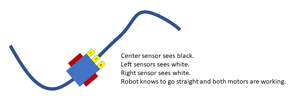
If the center sensor sees black, left sensors sees white, right sensor sees white, the robot knows it to go straight and both motors are working.
-
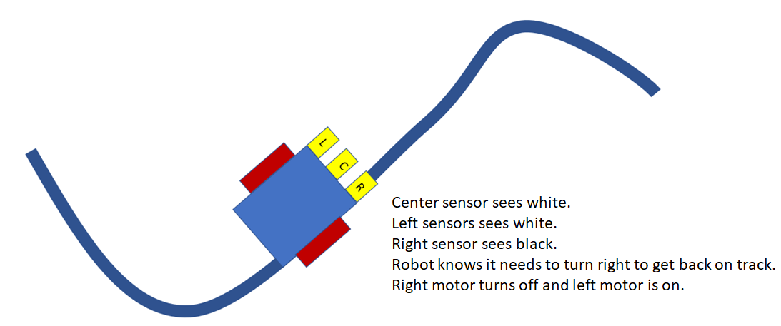
If center sensor sees white, left sensors sees white, right sensor sees black, the robot knows it needs to turn right to get back on track. This is done, by turning the right motor turns off and left motor is on.
-
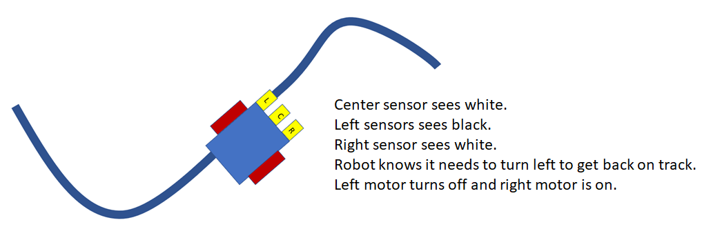
If center sensor sees white, left sensors sees black, right sensor sees white, the robot knows it needs to turn left to get back on track. This is done, by turning the left motor turns off and right motor is on.
-
This is all done using the C++ program and is provided in the presentation section.
Visual for all these directions are shown below.
Go straight
Turn Left
Turn Right
When the robot was followig the line, it was very smooth for wide track (3.0") but it was sloppy for 1.0" track. These can be seen in two videos attached in the "Presentation" section.
Analysis
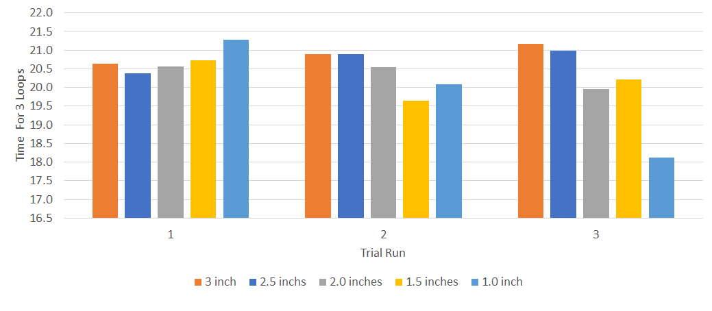
For this project, 5 different track widths were tested to see robot's response. For each width, three trial runs were done to reduce experimental error. Time to complete three laps were used and compared to see if different thickness made any difference to robot's response time.
The results from these runs are shown below.
| Trial Run | Track Width (inches) | Time to Complet Three Laps (seconds) | Average Time (seconds) |
| 1 | 3.0 | 20.63 | 20.89 |
| 2 | 3.0 | 20.89 | |
| 3 | 3.0 | 21.16 | |
| 1 | 2.5 | 20.38 | 20.75 |
| 2 | 2.5 | 20.89 | |
| 3 | 2.5 | 20.98 | |
| 1 | 2.0 | 20.57 | 20.35 |
| 2 | 2.0 | 20.54 | |
| 3 | 2.0 | 19.95 | |
| 1 | 1.5 | 20.72 | 20.20 |
| 2 | 1.5 | 19.65 | |
| 3 | 1.5 | 20.22 | |
| 1 | 1.0 | 21.27 | 19.83 |
| 2 | 1.0 | 20.08 | |
| 3 | 1.0 | 18.13 |
The raw data is also shown in graph format below.
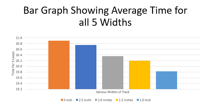
Average time from each width is also shown below.
Conclusion
The conclusions from the experiment were very surprising. My hypothesis was wrong. In this case, the robot was able to follow all 5 track widths. The following was concluded:
-
The robot ran very smooth on 3.0" wide tracks, but the time was slowest.
-
As the track width was reduced, the robot was overshooting when near the turns. Due to this overshoot, the robot was going "left -right-left-right", on thin track.
-
What was interesting was that, even though the robot was going "left-right-left-right", on 1.0" track, it had the fastest time.
-
As the track width decreased, the time decreased.
-
On average, the robot took about 20 seconds to complete three laps around the track regardless of width.
Application
From this project, it can be seen that IR sensor robots can follow the directions if the path is defined well. From this experiment, I can see line following robots can be used in restaurants to serve food. The restaurant owner will have to define the path well. This technology can also be used for self-driving cars. However, for that many more sensors will be required to detect other obstacles in the way.
Sources Of Error
There are few sources of error in this experiment. They are:
-
The battery life impacted how fast the robot went around the track. As the battery life drained, the motors were not turning that fast.
-
IR sensors are very sensitive and depending on test time, they required adjustments which impacted robot’s response time.
-
The lines varied slightly from the required thickness.
-
Start and end time on timer was not always at same spot.
Citations
References in MLA Citation Format
1: “The History, Trends, and Future of Infrared Technology.” DSIAC, dsiac.org/articles/the-history-trends-and-future-of-infrared-technology/. Accessed 15 Dec. 2023.
2:“How Does an IR Sensor Work?” YouTube, YouTube, 1 July 2020, ww.youtube.com/watch?v=q11FJqHPQo4.
3: “IR Sensor: Basics, Types, Circuit, Working, Projects, Faqs.” Electronics For You, 29 Aug. 2023, www.electronicsforu.com/technology-trends/learn-electronics/ir-led-infrared-sensor-basics
4: Hughes, J. M. “Arduino: A Technical Reference.” O’Reilly Online Learning, O’Reilly Media, Inc., www.oreilly.com/library/view/arduino-a-technical/9781491934319/ch01.html. Accessed 29 Dec. 2023.
5: Team, The Arduino. “Getting Started with Arduino Products.” Arduino, www.arduino.cc/en/Guide/. Accessed 17 Dec. 2023.
6: “Arduino Uno REV3.” Arduino Online Shop, store-usa.arduino.cc/products/arduino-uno-rev3. Accessed 15 Dec. 2023.
7: Manzoor, Mariam. “How to Make Line Follower Using Three IR Sensor: Arduino Line Following Car.” How To Make Line Follower Using Three IR Sensor | Arduino Line Following Car, Blogger, 19 Mar. 2021, deeplift.blogspot.com/2021/01/how-to-make-line-follower-using-three-irsensor.html.