Wonderful Wings: How Wing Shape Impacts the Distance a Paper Plane Flies
Adeline Robertson
R. T. Alderman School
Grade 5
Presentation
No video provided
Hypothesis
Testable Question
How does the shape* of the paper airplane wing impact the distance it can fly?
*Shape = the curve and surface area of the wing
Hypothesis
If the camber* and surface area of the paper airplane wing is bigger, then it will fly better because the air going over the wing is faster, creating more lift
* camber = the curve of an airfoil
Research
How do planes fly?
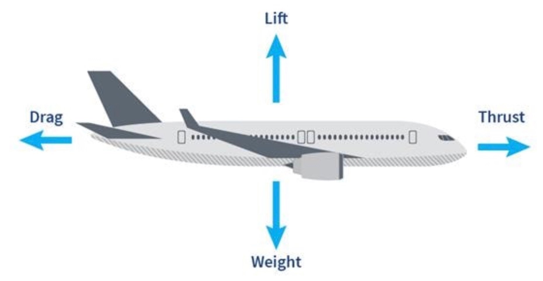
- Planes fly because of the FOUR FORCES OF FLIGHT
- The FOUR FORCES OF FLIGHT are:
- Lift
- Lift makes planes fly and stay in the air
- Lift is the opposite to weight.
- Lift is generated by the air going over the wing faster than under and the lower air pressure above the wing
- Thrust
- Thrust is what moves planes forward
- For an aircraft to move forward you need to have more thrust than drag.
- Drag
- Drag is the force that tries to slow something down or stop something
- The more air that hits a surface the more drag it creates.
- Weight
- Weight is how heavy something is
- Everything on earth has weight.
- The weight of an object controls how strong the lift needs to be.
- Lift
 Forces of Flight.” Pearson Airport, www.torontopearson.com/en/whats-happening/stories/whyyz/forces-of-flight.
How do wings create lift?
- Wings create lift because of Bernoulli’s Principle
- The air going over the wing is faster.
- The faster air going over the wing creates low air pressure and higher air pressure below the wing.
- Because the air is faster going over the wing gets past the trailing edge first which makes the air swoop under the wing.
- Because the air goes under the wing pushing the plane upwards.
- Stalls must be considered
- Stalls are feared by pilots because when the angle of attack is too high around 16 degrees and a decrease in lift making the plane drop.
- Wings are designed for different ideal takeoff angles
What is an airfoil?
- An airfoil is a structure made to manipulate the air flow to produce lift.
- The front end of an airfoil is called the leading edge.
- The back end of an airfoil is called the trailing edge.
- If you draw a straight line through the leading and trailing edge, it is called the chord line.
- The angle between the chord line and air flow direction is called the angle of attack.
- Draw a line between the upper and lower surfaces makes the camber line.
- Depending on the airfoil style there can be positive camber or negative camber.
- However the engineers build the wing the airfoil could be symmetrical leading to the airfoil having no camber.
- Camber and the angle of attack are important because they will impact how much lift the wings can create
 Leishman, J. Gordon. “Classic Airfoil Theory.” Introduction to Aerospace Flight Vehicles, 1 Jan. 2023, eaglepubs.erau.edu/introductiontoaerospaceflightvehicles/chapter/classic-airfoil-theory
Which shape of paper airplane wing should fly the farthest?
- Delta wings
- They have a triangular shape to their wing and if you change the angle you could make the delta wing be more like a straight wing so it would have more surface area or it would have less surface area if you make the wings come too close together but it could be the exact same plane every single time
- The delta wing is more like a triangle so it will act like a dart in the air so it will reduce drag
- Straight wings
- This wing is the simplest design of all paper airplanes
- The straight wing is a wing that takes on the shape of a rectangle and is the least aerodynamic design of wing because when the air hitting the plane will hit the wing straight away instead of smoothly running into a delta wing so this plane will create a lot of drag
- Swept back wings
- This wing poses a rearward slant from the root of the wing resembling the configuration of fighter jets and commercial airplanes
- This design has less drag and it boosts speed and travel distance of a paper airplane
- Wings with upwards folds
- These are small vertical extensions at the end of the wings
- They could be at the tip of the wing or on a delta wing you could cut two little slits into the trailing edge and fold the rectangle upward
- Gull Wings
- They have a visible bend near the inner wing
- They are often described as having better flying capabilities
Why does a gull wing have better flying capabilities?
Reasons the gull wing has better flying capabilities are:
- The gull wing has a visible bend in inner wing section.
- There is better visibility by thinner wing near fuselage.
- This design of wing was first used on glider.
- The gull wing resembles a seagull wing.
- This wing design was used in World War 2.
- The gull wing design was used for taking off of ships easier.
Why are swept back wings used on jets instead of straight wings?
- Where did swept back wings come from?
- The German aerospace program in world war 2.
- The Americans found the planes and began studying the wing shape.
- Straight wings could not handle the sonic shocks caused by jet engines increasing the speed of planes.
- Straight wings would cause air shocks to form on the top of the wing, making them shake, but swept back wings delayed the shock waves, allowing the jet to fly as fast as fast as the engines would create thrust.
What did the Americans learn from studying swept back wings?
- They studied the planes wing configuration in wind tunnels and they learned:
- That the placement of the engines nearer to the body of the plane would result in major fluttering (Looked like the wings were made of Jello, flapping like a birds)
- Placing the engines on two points along the wings, one closer to the tip and one near the body, would control the fluttering and allow for smoother flights.
- In theory swept back wings on a paper airplane should:
- Reduce drag because the shape of the wing is more like a dart so it will cut through the air
- This design boosts speed and flight distance because it has less drag and the same amount of thrust so it will have a longer flight distance
- Low profile edges minimize the surfaces that can create drag
- Reduces turbulence because it has a less obstructive way of cutting through the air
After this research, I concluded that swept back wings are probably not the best type of wing for a paper airplane, since it doesn’t use engines to stabilize the wings fluttering.
Other factors that can impact the flight of a airplane
- Nose Shape
- Wherever the nose is pointing you will go
- Nose shapes can be blunt, sharp or pointy
- Blunt nosed planes is the nose shape on an commercial airplane
- Sharp noses are found on supersonic planes so they can be more aerodynamic
- Pointy noses are found on military aircraft
- Weight
- The weight of the plane impacts how much it costs to make the plane and be able to fly in the plane
- The more weight a paper airplane has the more lift a paper airplane needs to create
- The more weight a airplane has the faster the plane and results in more fuel usage and shorter flight
- Vertical and Horizontal stabilizer
- The vertical stabilizer is on the plane because without it the nose of the plane would have a side to side motion this is called yaw
- The horizontal stabilizer is there because without it the plane would have an up and down motion with its nose. This is called pitch
What is important in a airplane design?
- The material the plane is made of
- Aluminum
- Carbon Fiber
- Fiberglass
- Steel
- Wood
- Fabric
- Engine placement
- Going back to background research about swept back wings when they were testing the wing design they had to place the engines in the right place otherwise fluttering would happen.
- Safety (including reliability)
- Industry Standards
- Making sure all the planes are made the same
- Redundancy
- All planes are required to have two engines and can fly with only one
- Computers
- Failsafe computers stop pilots from doing something unsafe
- Well trained Pilots
- Having well trained pilots can reduce the risk of crashing because they could have already done something like this problem before and deal with it to have a safe landing instead of a crash
- Industry Standards
- Stopping a plane
- Brakes use friction to stop the turning of the wheels
- Some planes have a anti lock system to stop the wheels from skidding
- Struts
- These are like the legs of the landing gear
- Struts are connected to the wheels of the landing gear
- Shock Absorbers
- These are giant springs and pistols under the wing and nose landing gear
- Shock Absorbers absorb bumps and rocks while taxiing
- Makes taxiing smooth and easy to maneuver the plane
- Flaps and slats on a wing
- A slat is a moving part on the leading edge of the wing
- A flap is a moving part on the trailing edge of the wing
- Pointing the flaps towards the tail and the slats forward give the wing a bigger surface area
- Pointing the slats and flaps slightly downwards increases camber
- Pointing the flaps vertically increase drag and the plane slows down for landing
Variables
| Variable Type | Description |
|---|---|
| Manipulated Variable |
|
| Controlled Variables |
|
| Responding Variable |
|
Procedure
MATERIALS
Material list for experiment
- 24lb paper (for at least 5 different planes)
- Long skinny sticky notes
- Measuring tape
- Tape (scotch tape, to hold measuring tape)
- Paper airplane book / online designs
- Big space (no obstructions, standard air flow)
- Ruler
- Scissors
- 50mm Paper clips
Material list for paper airplane launcher
- One 1 inch x 8 inch piece of pressure treated spruce
- One 2 inch x 4 inch piece of pressure treated spruce
- Screws(2.5 inches long)
- Elastics
- Drill
- Ruler
- Mitre saw (ask adult for help)
- Ryobi electric hand sander
- Protractor (to measure angle)
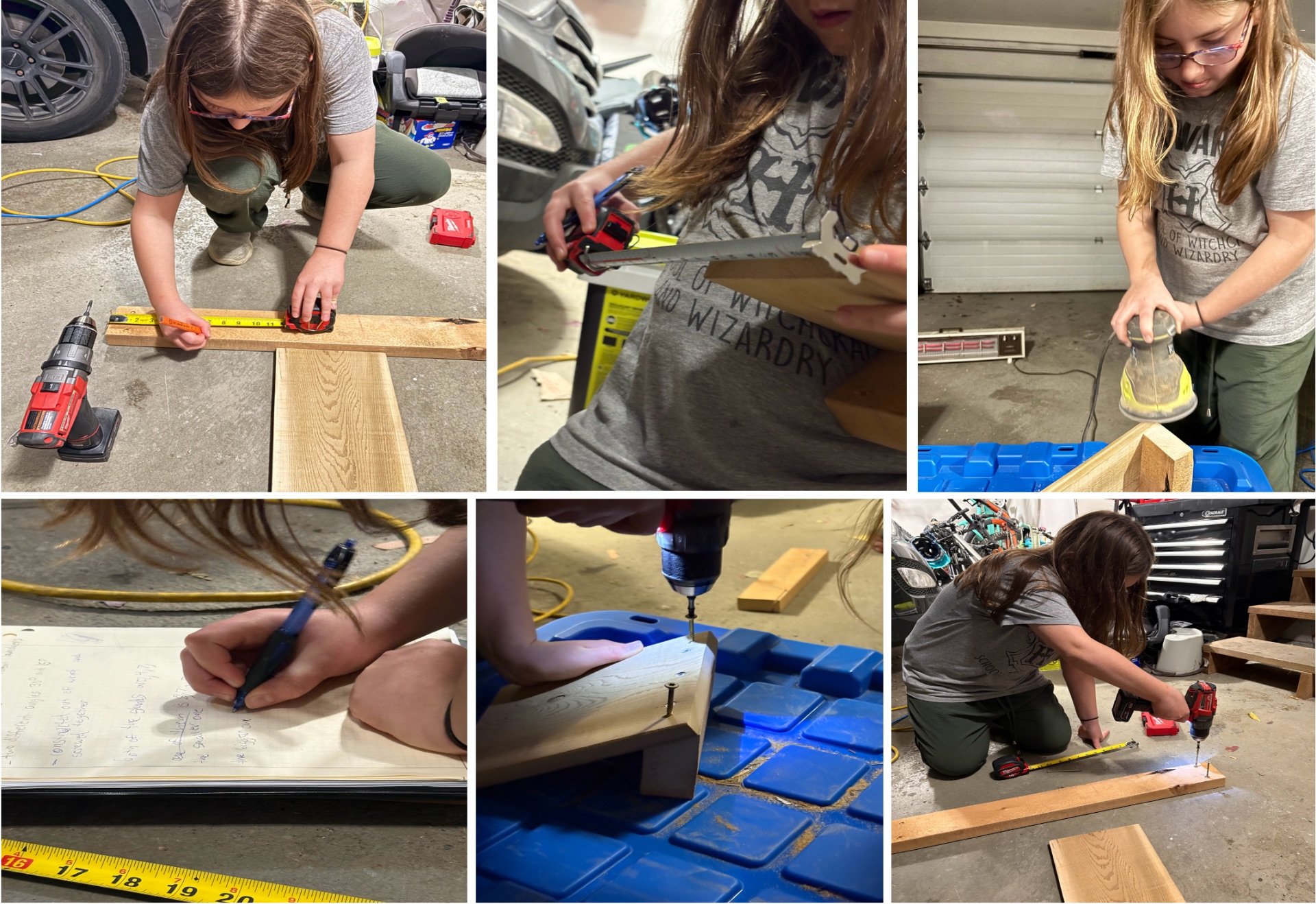
How to make the paper airplane launcher
- Measure width of and cut launch ramp piece
- For the experiment measure a 1”x8”x8 piece of pressure treated spruce
- Cut out the measurements with a mitre saw to have a 1”x8”x8 piece of wood (ask adult for help)
- If you change the width of your wood where you chose to put the screws is very important because you could have an uneven launch because the launch could be more straight
- Would recommend for making the launcher the width of the board should be 8 inches or wider
- Mark the width of the launch ramp onto the 2x4 board for the base of the launcher
- This board will be used to raise the the angle of the launch ramp
- Choose to make this board the same width as the launch ramp so it would have more stability and portability
- Cut the board at the mark you just made for the base of the launcher
- For safety have an adult cut the wood
- Cut an angle into the edge of the 4 inch side of the board
- In this experiment 15 degrees was selected for the launch angle because it was closer to plane takeoff angles
- Use a protractor to mark 15 degrees
- The surface that you cut is where you will connect them together
- Connect the two boards together using three 2.5 inch screws
- The screws need to be equally 2 inches apart
- Drill the two screw posts in 1 inch away from the edge of the launcher
- Leave 1 inch of the screw out of the wood so the elastic has something to hold onto
- Sand the edges so there will be no sharp edges or splinters
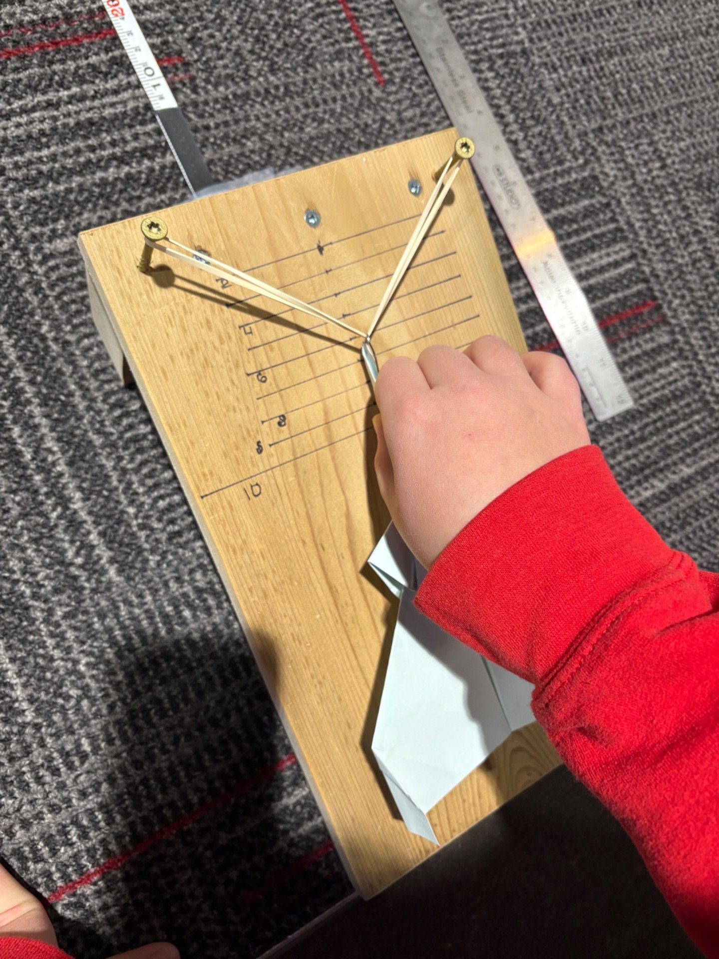
- Install the elastic around the two screw posts
- Draw nine horizontal lines 1 cm apart and beginning 1 cm away from the elastic
- Used to control the amount of thrust to make sure each plane will have the same amount of thrust so we do not create another manipulated variable
- Write the numbers 2,4,6,8 and 10 with 2 starting at the first line
- Make sure the numbers are at every other line after the 2.
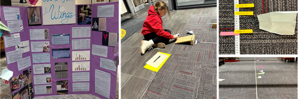
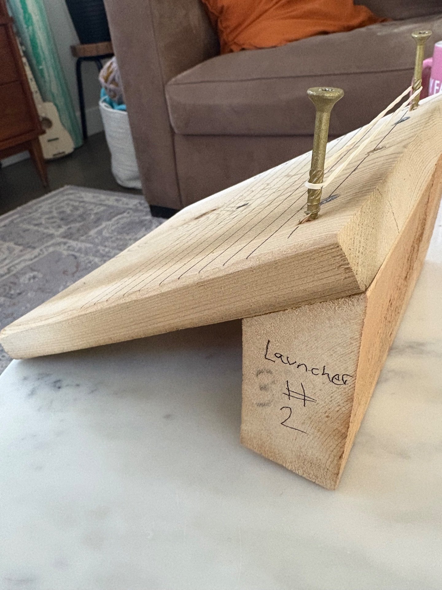 Launcher
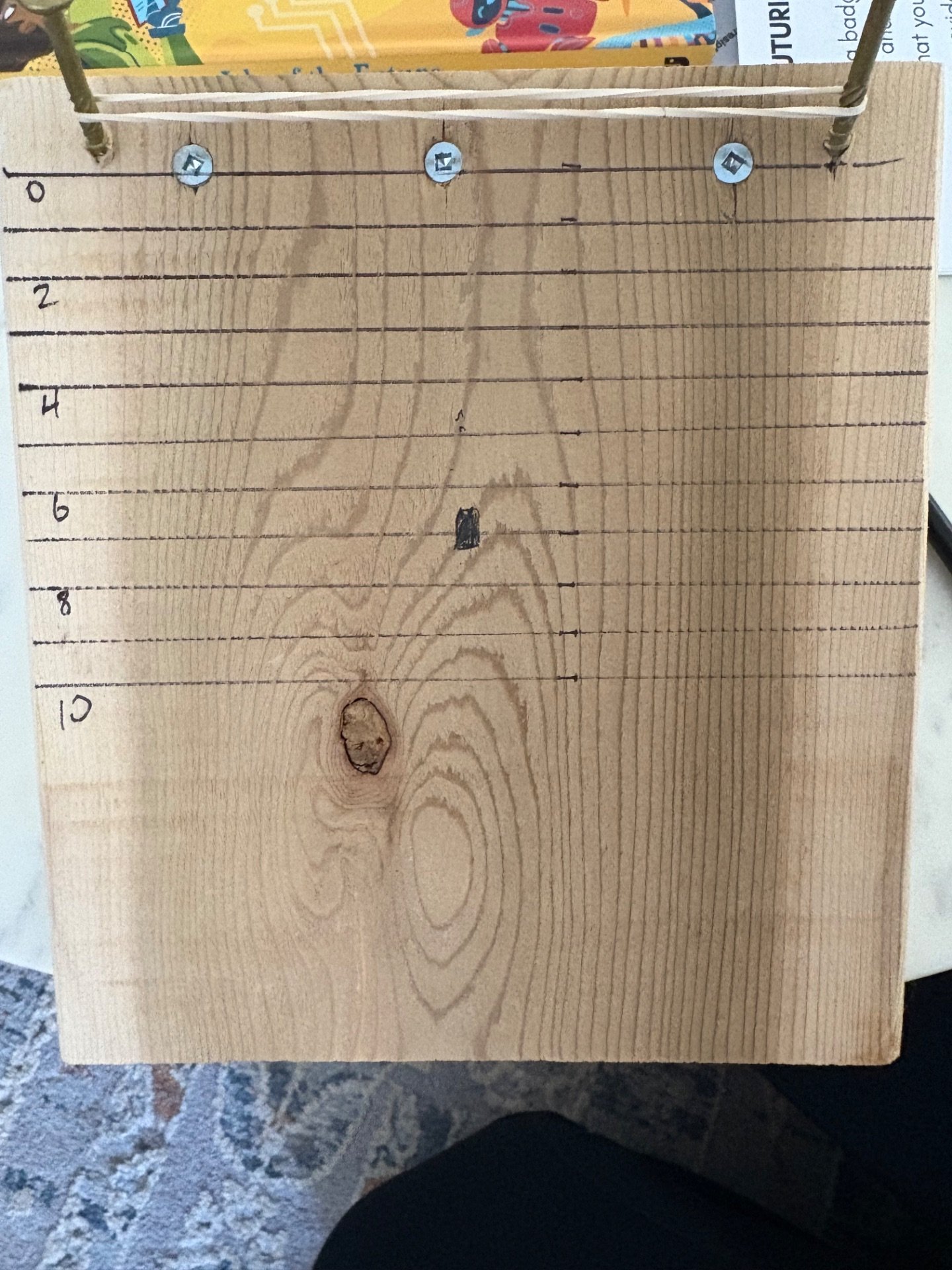 Launcher line markings
MAKING THE PAPER AIRPLINES
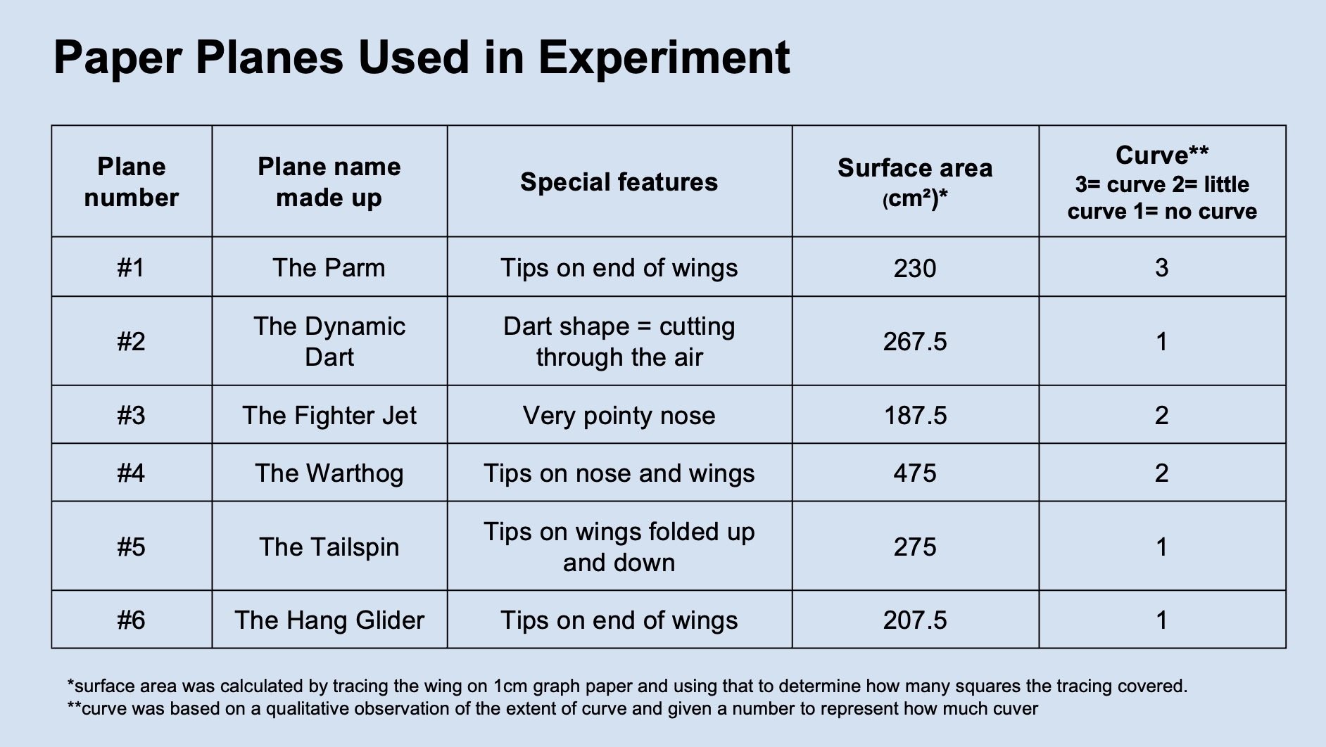
It is important to have a range of airplanes with different styles and wing shape and sizes to test the hypothesis. SIX airplane were used for this experiment:
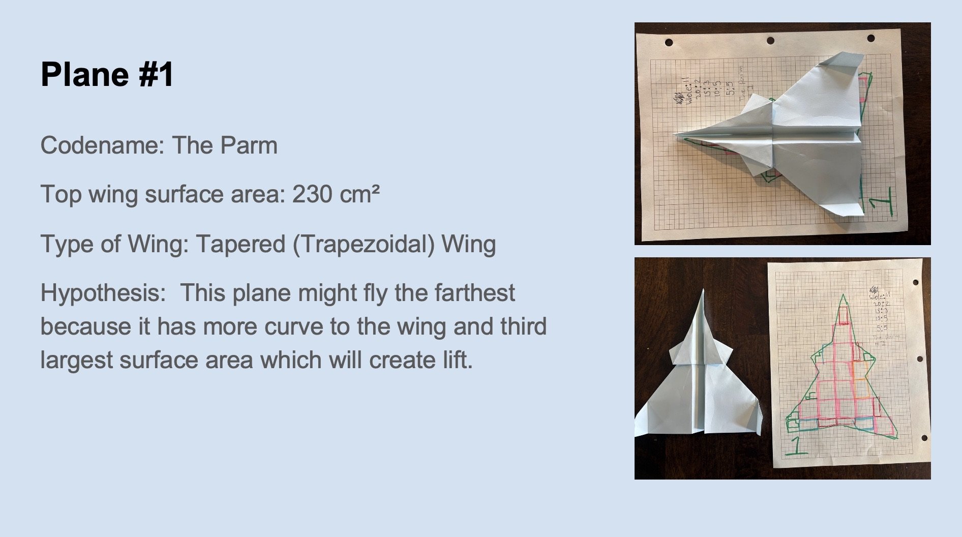
- Plane #1: the parm
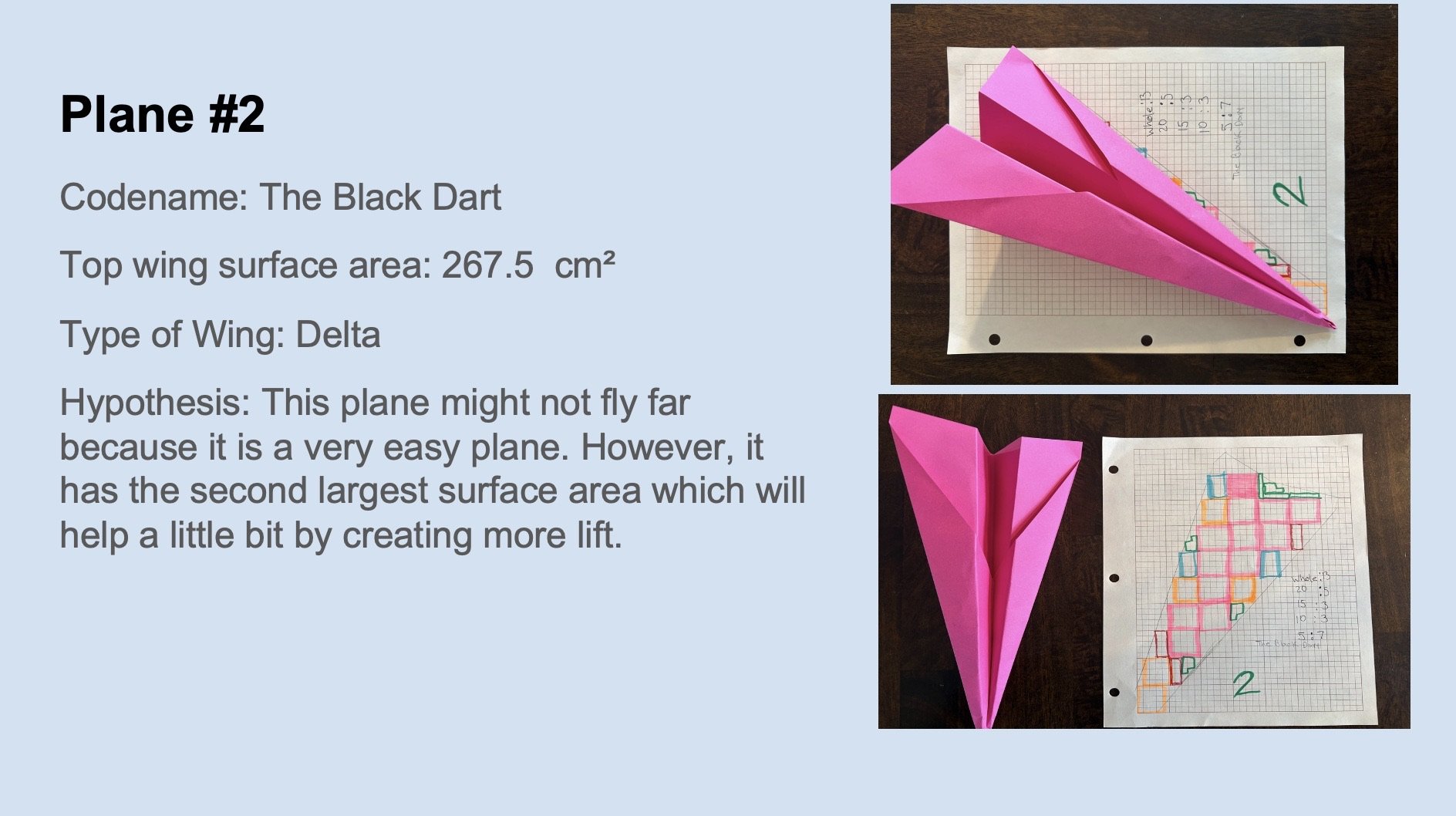
- Plane #2: the black dart
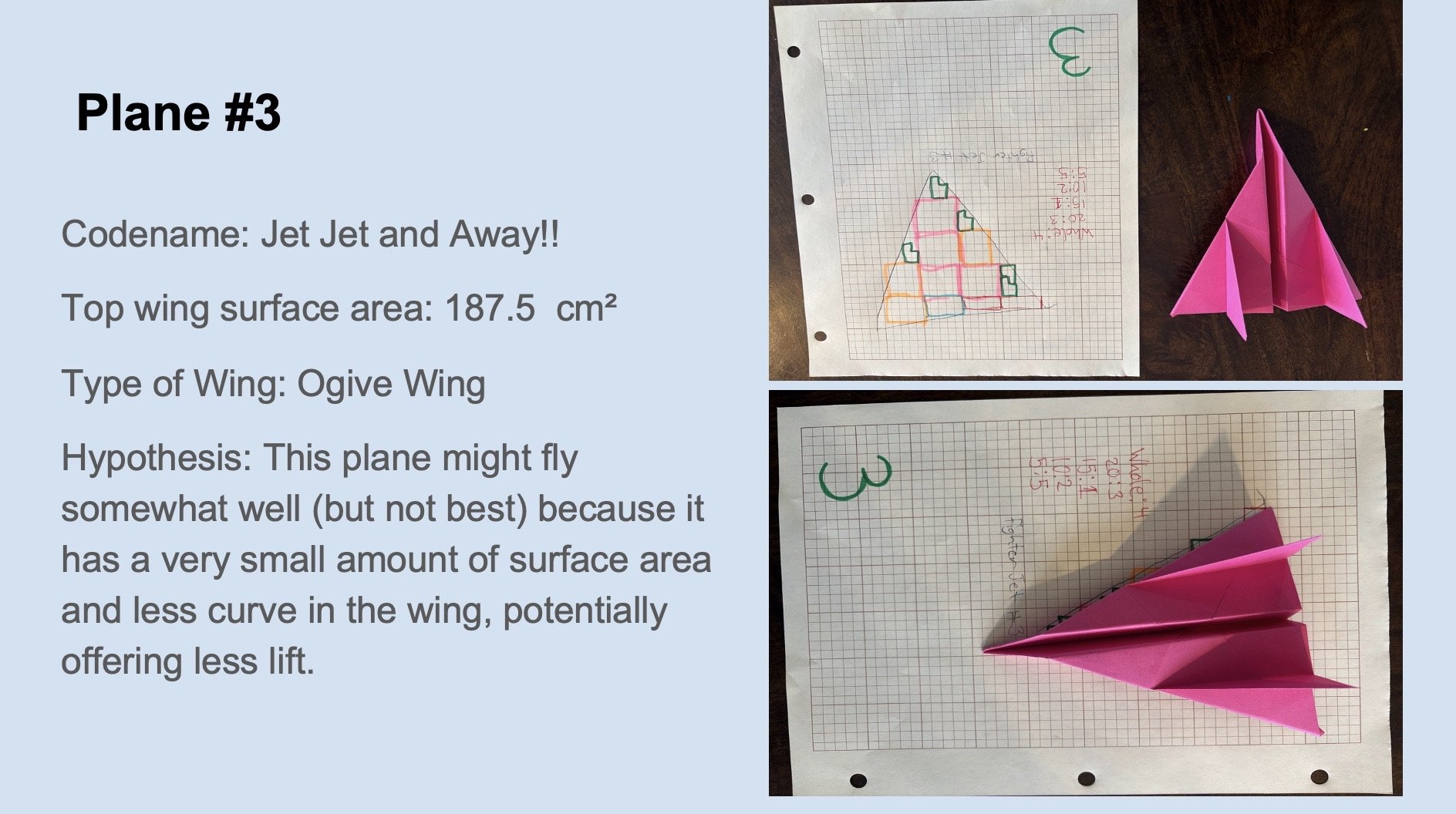
- Plane #3: jet, jet and away!
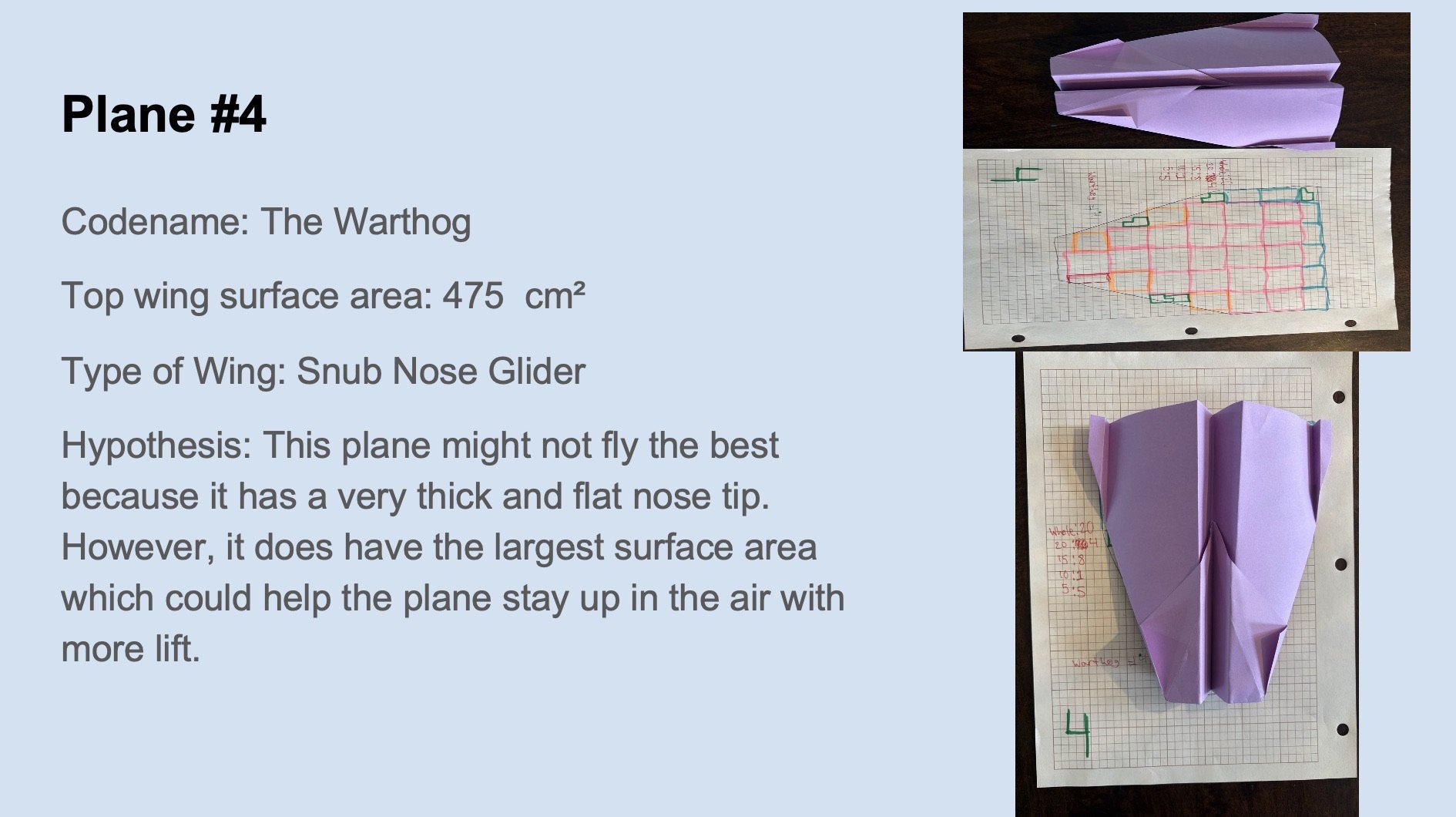
- Plane #4: the warthog
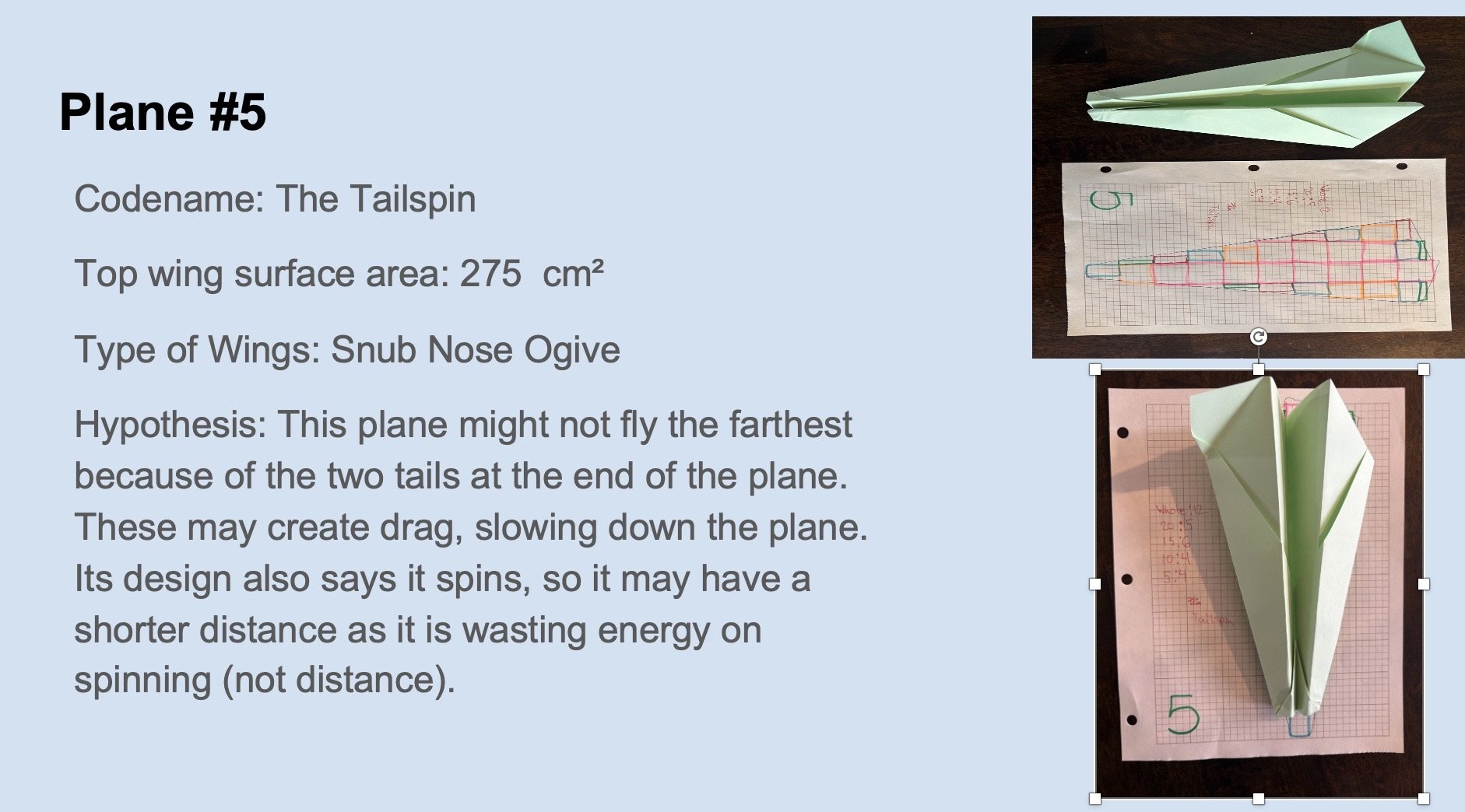
- Plane #5: the tailspin
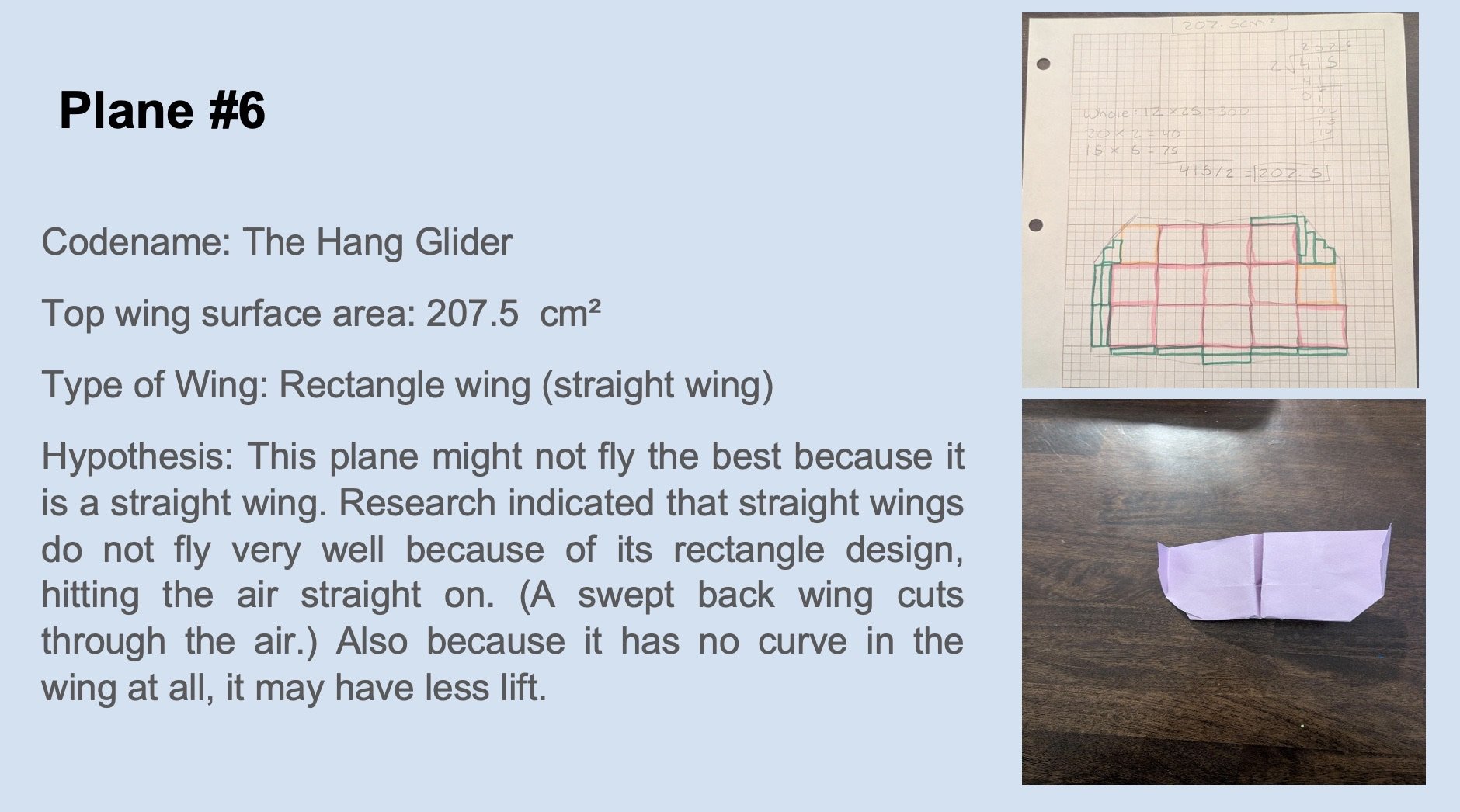
- Plane #6: the hang glider
PROCEDURE
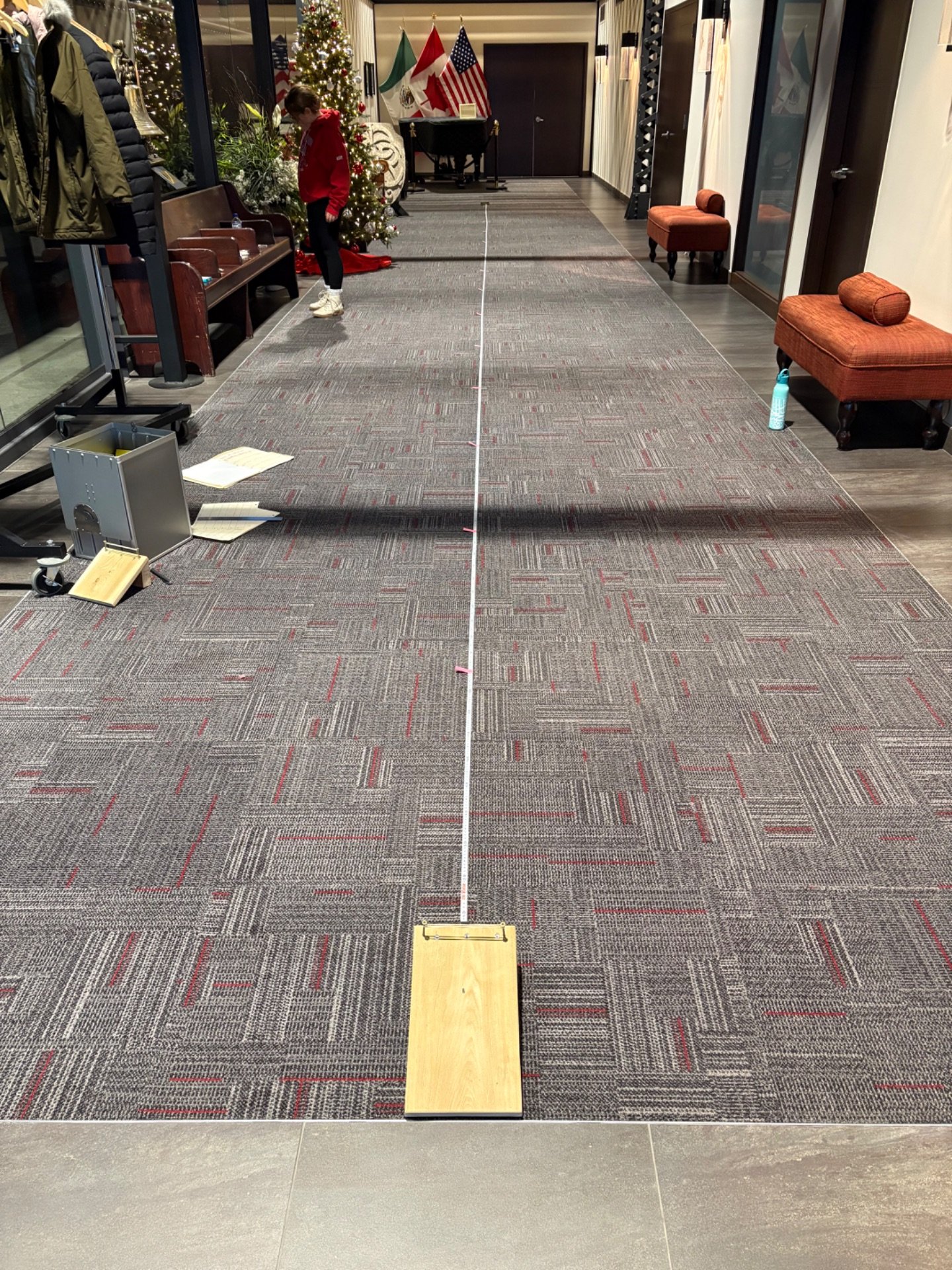
Experiment set up procedure
- Find a space that is 16 m long and 600 cm wide
- Gather materials
- Take a measuring tape, extend it and lay it down to 14m in length
- Tape down measuring tape to secure it to the floor
- Add long skinny sticky notes to the measuring tape at each meter
- Place down the airplane launcher at the one end of the measuring tape (0cm)
- Measure both sides to make sure the airplane launcher is centered against the measuring tape
- Add paper clips onto middle and in the crease and nose of the plane
- Attach paper clip that is connected to the plane onto the elastic by the curved part of the paper clip
- Pull back the the nose of the plane to the 8 cm marking on the launch setting
- Release the plane to launch it (ensure nothing in its way, like fingers)
 Experiment Setup
 Attaching the plane to launcher
Experiment procedure
- Create two observation charts
- With 4 columns (Plane Type, Flight #1, Flight #2, Flight #3) and 6 rows for each of the plane designs (make sure to design charts on slides so lines are clean)
- Make one for quantitative data and one qualitative data
- Print out one for quantitative observations and one for qualitative observations
- Launch your first plane (Plane #1)
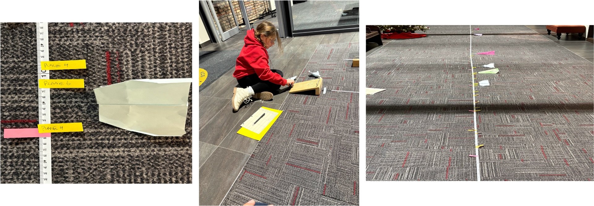
- Measure were the first plane landed and add a long skinny sticky note and mark it (e.g., plane #1 flight #1)
- Write down your observations on the observation chart ( make sure the measurement is on the quantitative sheet and the flight observations on the qualitative sheet)
- After you finished launching each plane once do the same thing 2 more times so each plane will have flown 3 times each
- Take your plane back to the launcher and repeat steps 3-5, but noting flight #2 and #3 on sticky notes
- Repeat steps 2-6 with the remaining planes
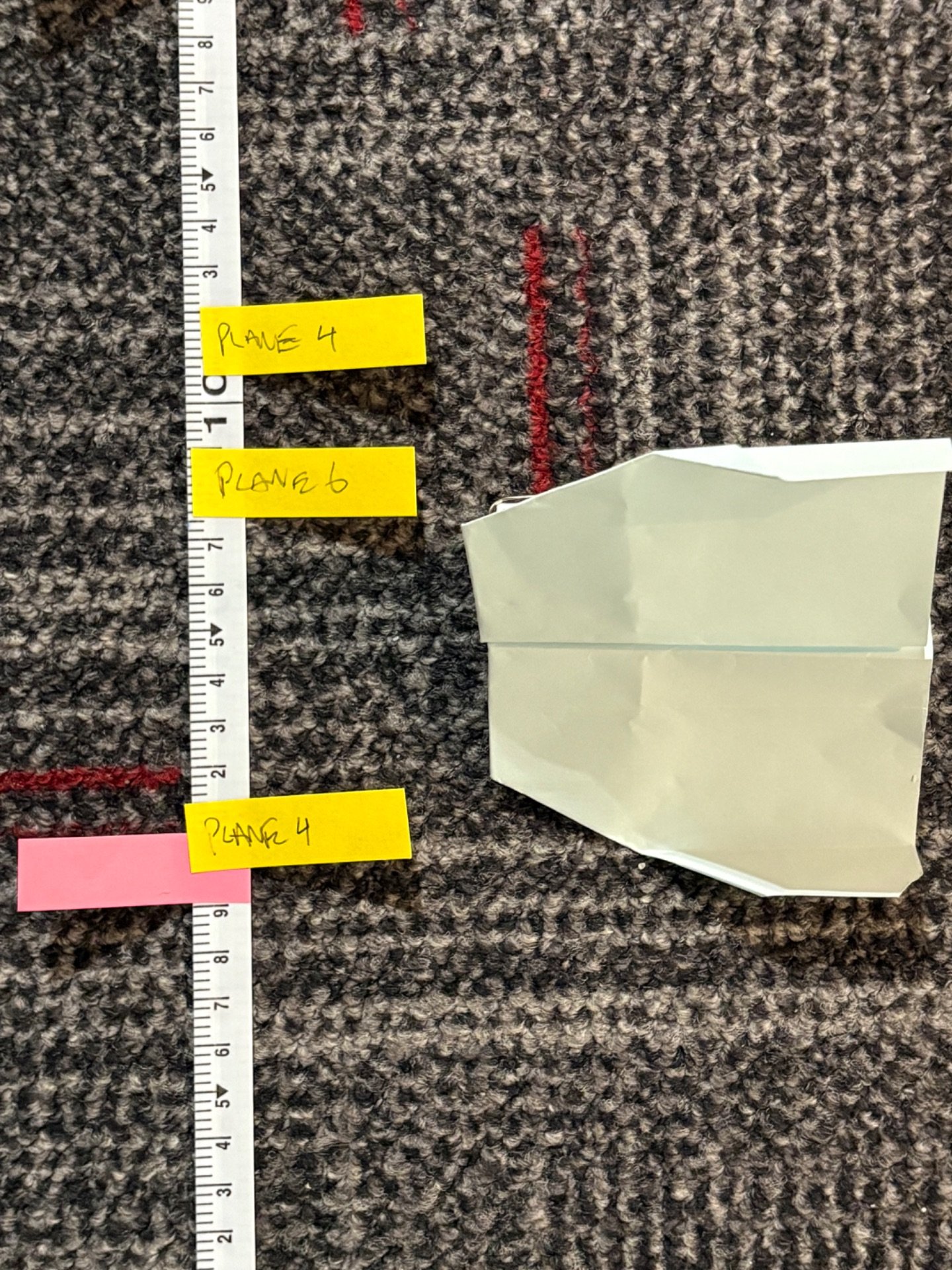 Using Post-It to mark plane distance
Observations
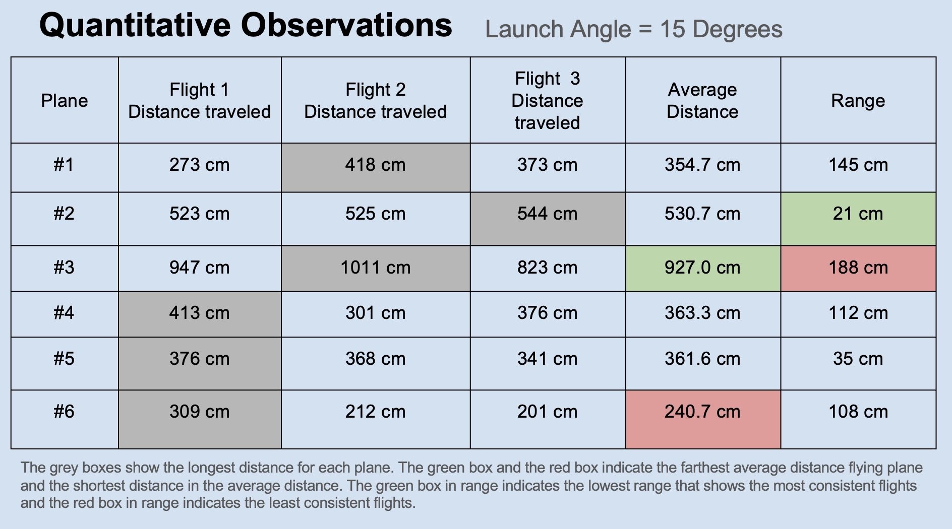
Quantitative Observation Chart
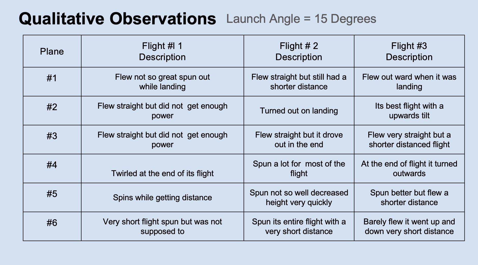
Qualitative Observation Chart
 Me doing the experiment and making observations
Analysis
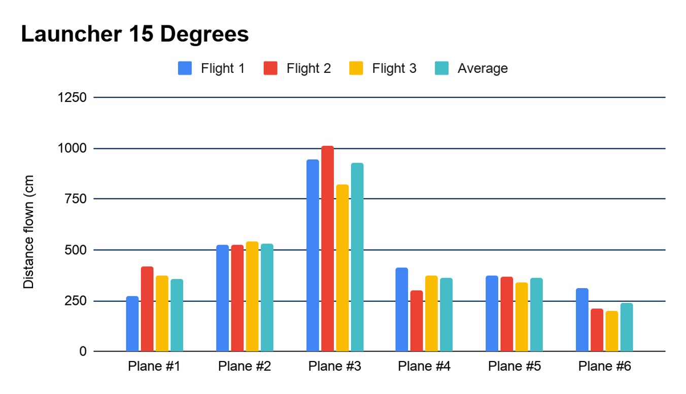
ANALYSIS CHARTS
ANALYSIS
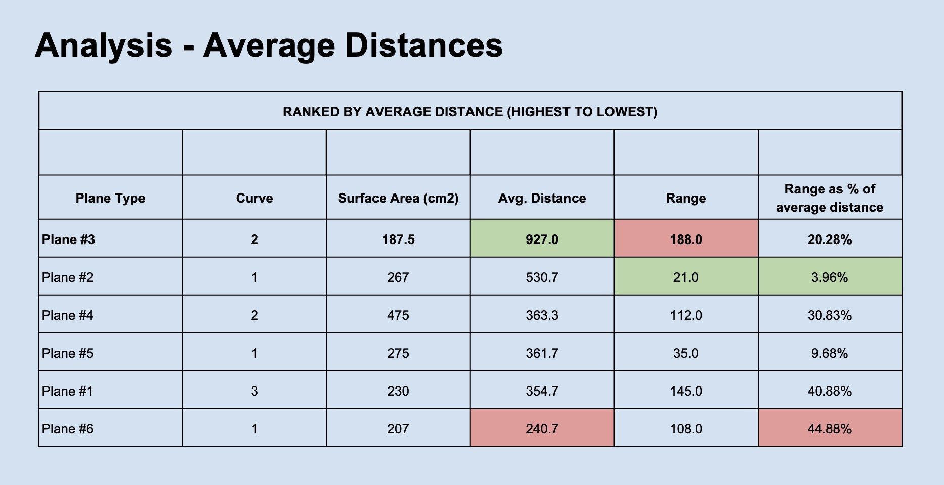
Average Distance
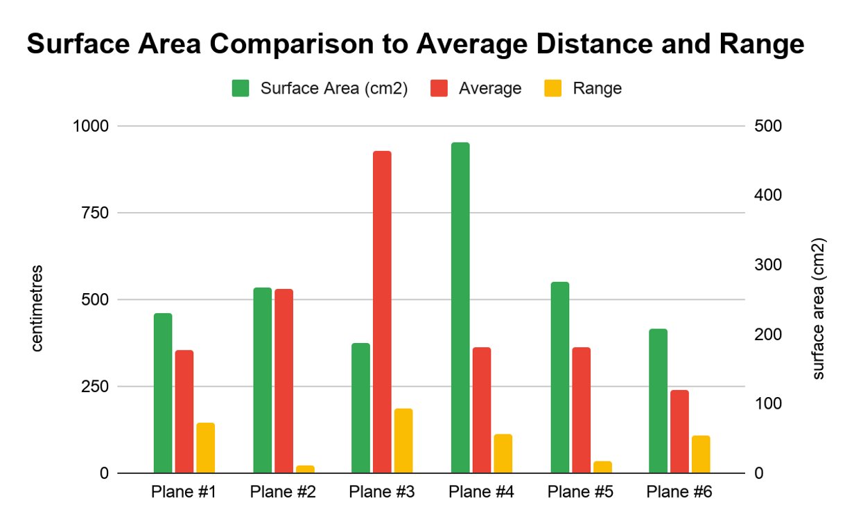
a) What does the data tell us? It was important to calculate average and range as not every plane flew consistently.
While calculating averages, it was found that no plane had the same distance in all 3 launches. The averages showed that even Plane #3 flew furthest on average, by around 400 cm to the next farthest planes (Plane #2).
Plane #2 and Plane #5 had similar wing surface areas and curves, but they still flew different average distances (Plane #2 flew 170cm more on average). This suggests other design differences (like weight distribution, nose shape, or folds) impacted affected distance.
b) What did you learn? The results were inconsistent because it was impossible to control every variable (for example: tiny differences in the launch, air movement, and how each plane was folded). The averages helped me see which plane flew farthest overall, and the ranges helped me see which plane was most reliable.
My data suggests that Plane #3 was best for distance, but it may not be the best for reliability.
c) What connections can be made? In real airplanes, engineers test wing designs to balance distance and consistency. Planes need to fly in a way to be depended on. Better wing design can improve efficiency, which can reduce fuel use, lower cost, and be better for the environment.
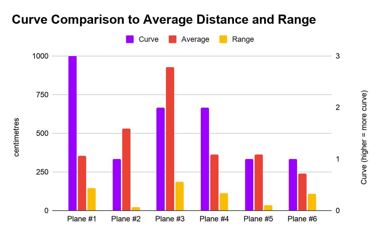
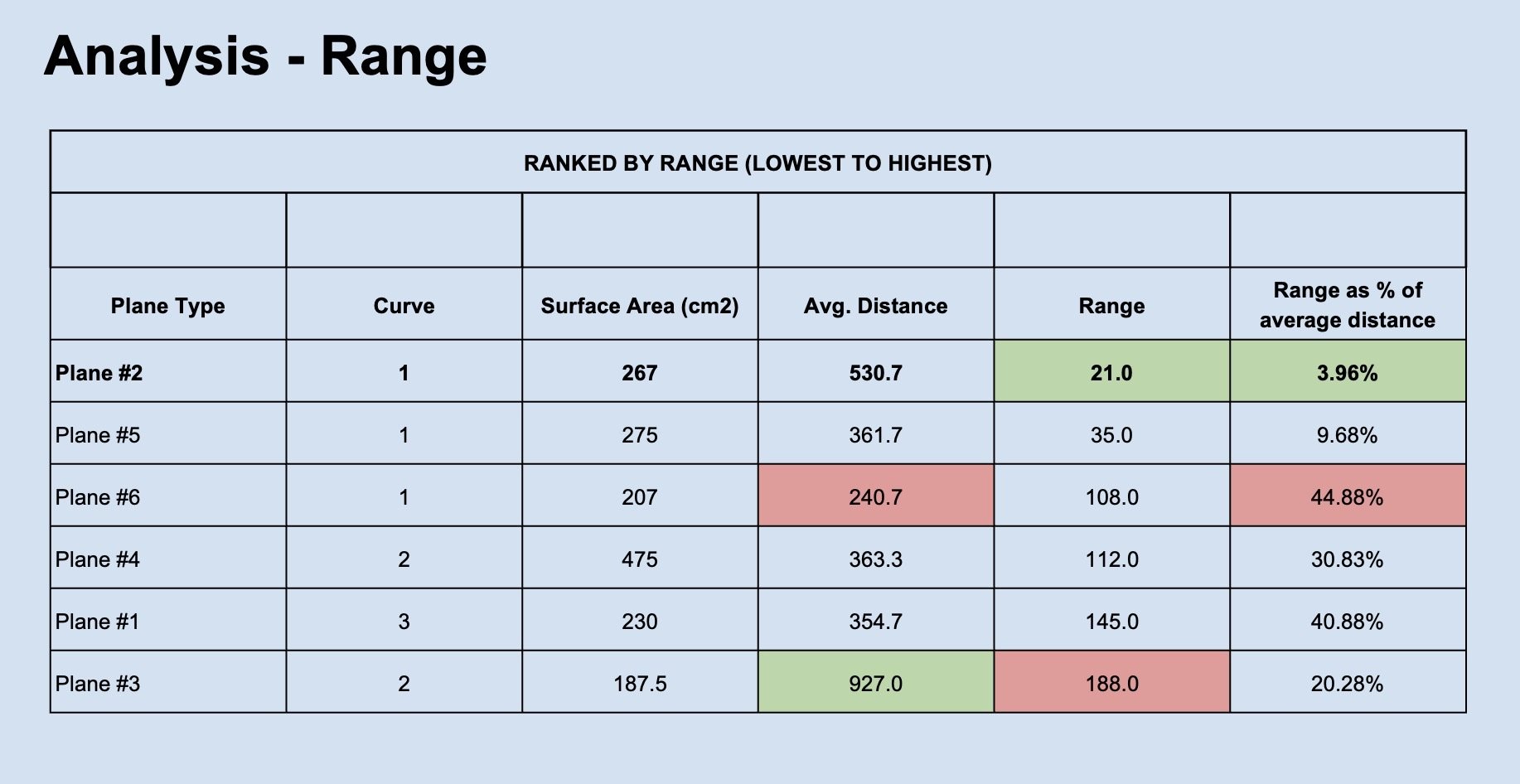
Range
a) What does the data tell us? To understand consistency, range was calculated to determine the range of flight distances. Range was calculated taking the highest distance and subtracting the shortest distance. For planes, distance is important, but can be an issue if that distance can not be reached every time.
In the experiment, the plane that flew the farthest (Plane #3), had the worst (largest) range (188cm). However, the second farthest plane (Plane #2) on average had the smallest range.
b) What did you learn? With only 3 launches, it would be important in a future experiment to do more launches to see whether inconsistency remained with Plane #3 and Plane #2. This also points to the fact that distance may not be the only important factor to consider.
c) What connections can be made? Conclusions are hard when planes do not produce the same results each time. No one wants their plane to fly one distance one time, and then not make it the next. This could mean that there are new things to consider in future experiments and makes it hard to decide if wing shape determines distance.
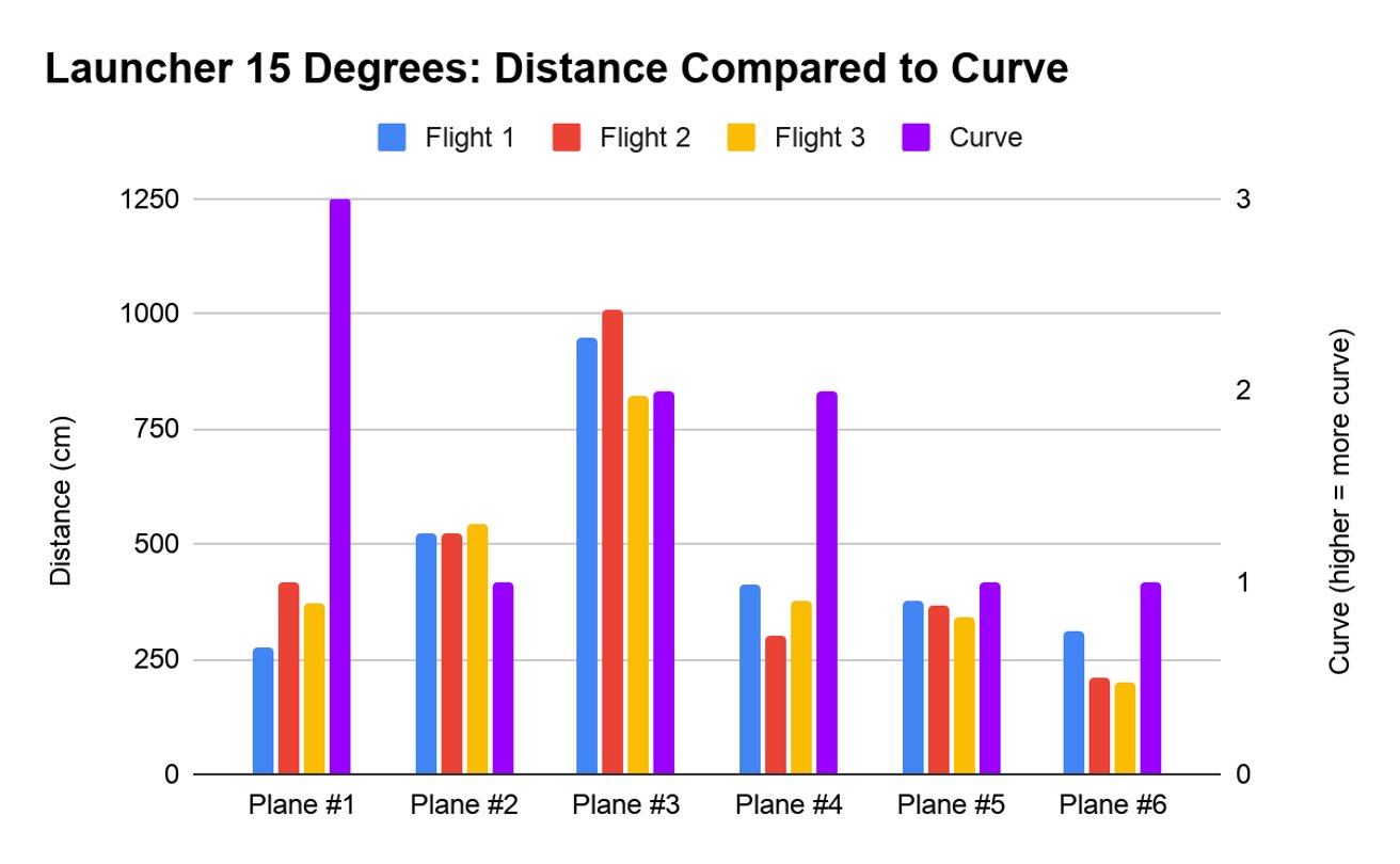
Wing curve impact on distance
a) What does the data tell us? Based on average distance, it did not indicate that the curve of the planes’ wing impacted the distance it flew while being tested. Planes with no curve were the 2nd, 4th and 6th farthest travelling planes. Moderate curve were 1st and 3rd and the most curve was the 5th farthest travelling plane.
b) What did you learn? The experiment showed that the plane that had the most curve did not fly the best or farthest. This is the opposite of the hypothesis being tested.
c) What connections can be made? Real airplanes use curved wings (and have flaps that they can adjust and change) to increase or decrease lift, but engineers must balance lift with drag so the plane is efficient and stable. This experiment suggests more curve didn’t automatically mean farther flights, so wing design involves trade-offs (lift, drag, stability). Next time I would change only the wing curve on one plane design to determine if it really is curve or something else that makes a plane fly farther.
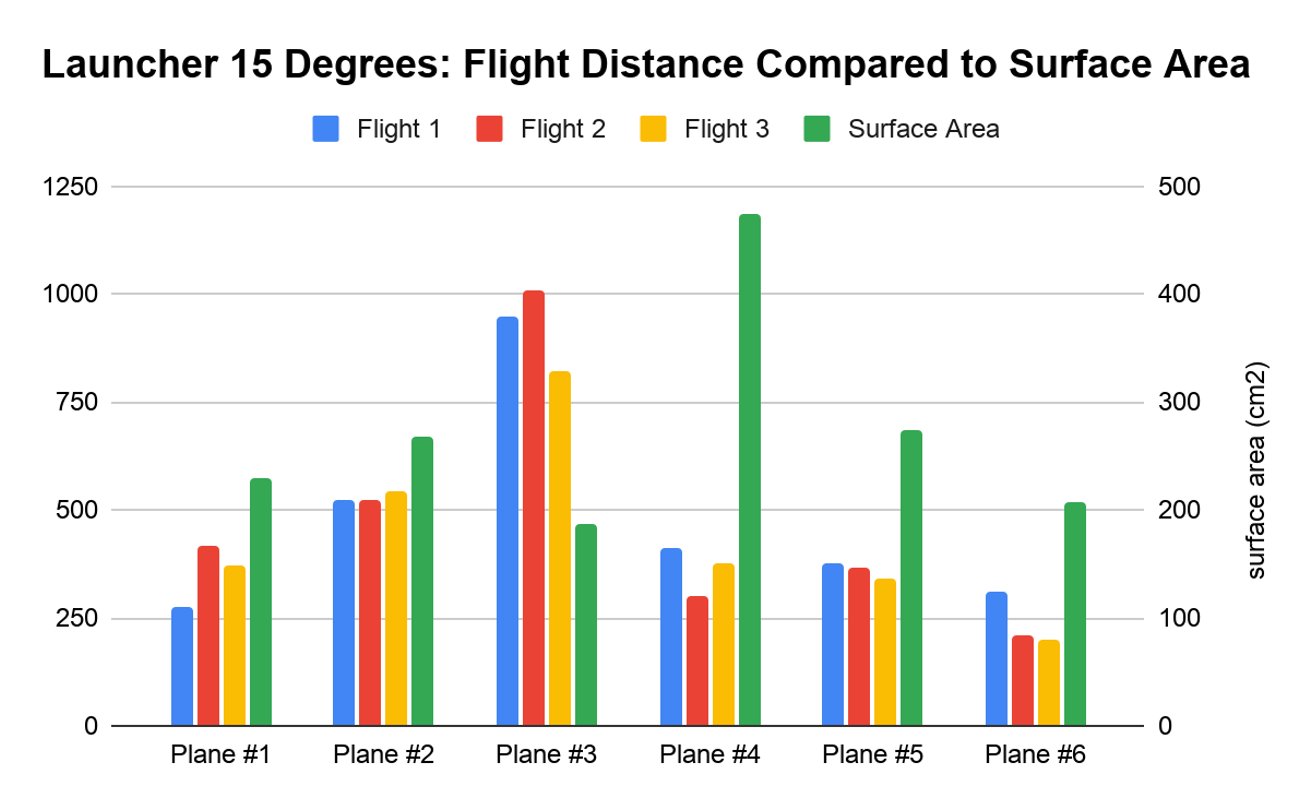
Surface area impact on distance
a) What does our data/ prototype tell us? Based on average distance, the plane with the smallest wing surface area flew the farthest. However, the pattern on surface area was not consistent. The plane with the second-smallest surface area flew the shortest distance, and planes with the largest surface area were also among the shortest distances.
This suggests that surface area might be related to distance in my experiment, but it may not be the only factor. Other differences between the plane designs (like folds, weight balance, and nose shape) could also have affected the results.
b) What did you learn? The data suggests that surface area might be related to distance, but it may not be the only thing that causes a longer distance.
c) What connections can be made? In real airplanes, wing size is designed based on trade-offs. Bigger wings can create more lift, which helps planes take off and carry weight, but bigger wings can also create more drag. More draft can lead to bumpier flights. Smaller wings can reduce drag and help with speed, but they might need more speed to generate enough lift. This could mean the planes need more fuel.
How weight impacted flight distance
a) What does the data tell us? The weight of the paper was the same, but the design of each plane meant there was different weight balance. Although not measured, the experiment showed where the weight of a paper airplane was placed impacted flight distance. If a plane is too nose-heavy, it can dive down quickly. If it is too tail-heavy, it can tilt up and stall.
Two planes in the experiment also required cutting down the paper to make that plane design leading to some being lighter (and maybe having an easier time flying by being lighter).
b) What did you learn? The experiment showed that the planes with too much weight in the nose made the plane dive headfirst and To study weight fairly, a future experiment would need to measure the weight of each plane and maybe where it balances, and keep the design the same while only changing the amount of weight or where it is placed.
c) What connections can be made? In real commercial aircraft, weight and balance are very important. Airlines need to make sure the plane is not overloaded (too many bags) and that weight is distributed properly (passengers, luggage, and cargo are spread out). This is similar to paper airplanes, where weight can change whether the plane flies smoothly or dives.
Launch approach
a) What does the data tell us? In addition to calculating range, based on observations of plane distance and behavior, small differences in launching the planes (release timing, how the plane was attached, how smoothly it left the launcher) could change the distance. This happened even with a standard 15 degree launcher.
b) What did you learn? It is hard to make every launch exactly the same. Even small changes change how far it flies. These things make it hard to say that wing shape alone caused the distance differences. My results show which plane design worked best in my test setup, but also show that launch consistency is important for good data. The angle of the launch may also be a factor if the plane is designed for a different angle.
c) What connections can be made? Planes also use different takeoff angles depending on the runway length and airplane design. Consistent takeoff conditions and differences in speed and approach can cause a plane to perform different.
Another experiment could include two launch angles or improvements to the launch setup. This helps to determine if launch or wings are what helps flight distance.
Conclusion
CONCLUSION
Wing shape may have had an impact on distance, but the hypothesis can’t be proven from the experiment. This is because more than wing shape changed from plane to plane. This experiment can offer which design worked best, and helped build understanding of how an experiment would test wing shape alone next.
Based on the hypothesis, Plane #1 would have flown best. However, this hypothesis was disproven. Some factors that likely contributed to this were that it had more paper on the tip, which meant more weight which and led to the plane dropping to the ground sooner. The folds in the nose design was adding weight to the plane, while also slowing down the wind going over the wing reducing lift. Another factor making that plane fly short distances was the force of the launcher. The wings seemed to not be able to take the force of the launcher. When tested at home and throwing it softly by hand, it flew farther and smoother. This could be due to both the force of the launcher, but potentially also a launch angle not suited for Plane #1.
The plane that did fly farther was Plane #3, as it seemed to cut through the air because it cut through the air smoothly and stay straight. This plane had only minor curve and the smallest surface area. However, it was not consistent. The average distance across three flights was highest of all the test planes but had the greatest range (difference between longest and shortest test flight). Consistency is something that is important in plane and wing design.
Overall, it appears that wing curve did not have a relationship with distance planes flew, except for potentially being a factor with Plane #2. It appears that surface area does have some effect on distance flown. Other than Plane #6 (the only plane without a swept back wing) a smaller surface area led to longer distances.
LIMITATIONS
Each of the six paper airplanes had different wing shapes but also had other differences impacting airplane design like folds, nose shape, and weight balance.
This means wing shape was not the only thing changing in my experiment. As such, the results show which airplane design flew furthest but do not prove that wing shape alone caused the difference.
This points to a confounding variable in my experiment.
NEXT STEPS
Next steps for this experiment could go in two different directions:
One Plane Design - I could improve this experiment by testing wing design in a better way. I would choose one paper airplane design and keep it the same every time\, and then I would only change one wing feature\, like the wing curve or the wing surface area. I would also do more launches for each version (about 5–10) so I can compare the averages and ranges more confidently.
Different Launch Setup - For another next step\, I could improve the launch part of the experiment. In this experiment I only tested one launch angle\, so next I would test a few different angles to see which angle works best for the plane. I would also test different thrust settings (how far the launcher pulls back) to find a setting that gives more consistent launches. After I find the best angle and thrust\, I would test the planes again using the same launch settings so the comparison is better.
Application
Airplanes need the right wing design for the job. Wing and plane design are both important and different based on what a plane is designed to do.
For this experiment, findings around wing design related to distance allow us find ways to design planes that could use less fuel while taking off and in the air. This experiment could contribute to how we reduce pollution and extreme climate change associated with planes, and maybe even planes with smaller or more efficient engines, using less fuel.
My research could also lead to other design options to improve on the swept back wing. It could point to ways that engineers could mix different wing configurations or plane designs to improve distance (or other plane design goals).
Like this experiment, testing, especially one variable at a time, is important to learn about improvements to make.
Sources Of Error
- When testing the planes in a building where there was heaters and air conditioning, it could change air flow and could’ve knocked a plane out of its path
- In the middle of testing, there was a change of launch setting from 10 cm down to 8cm because the thrust of the launcher was too strong and the paper clips kept falling off
- Paper clips were used to hold the plane onto the elastic to keep launches consistent. The elastic kept falling off so the paper clip had to get retaped onto the plane which the plane would have better tension than others holding onto the elastic because some planes tape could of been too loose making the paper clip fall off in the air resulting in the force the paper clip makes while falling off is a downward motion and pointing the nose of the plane down to the ground and wherever the nose is pointing the plane goes where the nose is pointing bringing the plane down to the ground.
- Throughout the experiment the airplane launcher did not show consistent distances which could be tied to many factors impacting the experiment, either due to the launcher or plane design
- When making the planes, two planes needed a smaller piece of paper which made two planes lighter than the others.
- Even with the controlled variable of the amount of thrust (pulling back to a specific line), planes did not have a very consistent flight even though that's what this launcher setup was designed to manage this.
Citations
Websites Referenced
Animated Flaps and Slats. www.grc.nasa.gov/www/k-12/VirtualAero/BottleRocket/airplane/aflap.html.
BRIGHT SIDE. “Why Some Airplanes Have Rounded Noses and Not Pointed.” YouTube, 21 Nov. 2019, www.youtube.com/watch?v=5BnMn-AqX28.
“Design Innovation for Jet-Powered Flight: The Swept Wing.” PBS LearningMedia, 21 Mar. 2023, www.pbslearningmedia.org/resource/aeroeng-sci-eng-sweptwing/design-innovation-for-jet-powered-flight-the-swept-wing.
Dinogami. “How to Make an Easy Paper Airplane Launcher I Origami Plane That Flies Far.” YouTube, 8 Dec. 2022, www.youtube.com/watch?v=Gh7YAGPNHUU.
Eng. Ammar Samuel Yosef. “Gull Wing Configuration.” YouTube, 10 Oct. 2022, www.youtube.com/watch?v=YRkxZXTi6QQ.
Foldable Flight. “The EASIEST Paper Airplane Ever — How to Fold the Classic Dart Paper Airplane | Easy Tutorial.” YouTube\, 7 Dec. 2019\, www.youtube.com/watch?v=dCrxMJcVuyw.
Forces of Flight.” Pearson Airport, www.torontopearson.com/en/whats-happening/stories/whyyz/forces-of-flight.
Glazer, Neil. “Aircraft Wing Design: 10 Types of Aircraft Wings (Complete Guide).” PilotMall.com, 21 Dec. 2025, www.pilotmall.com/blogs/news/aircraft-wing-design-10-types-of-aircraft-wings-complete-guide?srsltid=AfmBOoofC4lnR7tx.
GPB Education. “Bernoulli’s Principle: How Planes Fly | Fast Forward Teachable Moments.” YouTube\, 2 Nov. 2020\, www.youtube.com/watch?v=YrSUxgiwoFk.
Incorrect Lift Theory. www.grc.nasa.gov/www/k-12/VirtualAero/BottleRocket/airplane/wrong1.html.
Leishman, J. Gordon. “Classic Airfoil Theory.” Introduction to Aerospace Flight Vehicles, 1 Jan. 2023, eaglepubs.erau.edu/introductiontoaerospaceflightvehicles/chapter/classic-airfoil-theory.
May, Sandra. “What Is Aerodynamics? (Grades K-4) - NASA.” NASA, 16 Apr. 2025, www.nasa.gov/learning-resources/for-kids-and-students/what-is-aerodynamics-grades-k-4.
NASA Glenn Research Center. “Airplane Parts and Function | Glenn Research Center | NASA.” Glenn Research Center | NASA\, 4 Oct. 2022\, www1.grc.nasa.gov/beginners-guide-to-aeronautics/airplane-parts-function/#vertical-and-horizontal-stabilizer.
---. “Four Forces on an Airplane | Glenn Research Center | NASA.” Glenn Research Center | NASA\, 21 July 2022\, www1.grc.nasa.gov/beginners-guide-to-aeronautics/four-forces-on-an-airplane.
Paper Folding Trick. “How to Make the Tail Spin Paper Airplane - Tornado in the Sky!!!” YouTube, 15 Aug. 2017, www.youtube.com/watch?v=EccKydSe__4.
Safety First. “What Makes Airplanes so Safe.” YouTube, 2 May 2025, www.youtube.com/watch?v=YP8Z9oqJPio.
The Efficient Engineer. “Understanding Aerodynamic Lift.” YouTube, 9 Feb. 2021, www.youtube.com/watch?v=E3i_XHlVCeU. Undercarriage Facts for Kids. kids.kiddle.co/Undercarriage.
Welcome | the Hangar Flight Museum. thehangarmuseum.ca.
“Why Aircraft Weight Affects Climb Performance.” Boldmethod Flight Training, www.boldmethod.com/learn-to-fly/performance/aircraft-weight-increase-and-why-affects-your-climb-performance.
WoW Fold. “How Do Various Wing Styles Impact the Flight Distance of a Paper Airplane? - WoW Fold.” WoW Fold, 6 Oct. 2023, www.wowfold.com/how-do-various-wing-styles-impact-the-flight-distance-of-a-paper-airplane.
Books Used
Brown, Jordan D. How Airplanes Get From Here . . . To There! Simon and Schuster, 2016.
---. How Airplanes Get From Here . . . To There! Simon and Schuster\, 2016.
Buckingham, Marie. Folding Paper Airplanes With STEM: For Beginners to Experts. Capstone Press, 2020.
Dk. Microbites: Flight: Riveting Reads for Curious Kids (Library Edition). National Geographic Books, 2020.
Harbo, Christopher L. Paper Airplanes, Captain Level 4. Edge Books, 2010.
Wilgus, Benjamin A. Science Comics: Flying Machines: How the Wright Brothers Soared. First Second, 2017.
Acknowledgement
I would like to thank my Dad for helping me do most of my procedure. When we were in Mexico we took a few hours of that day and dedicated it to how to make the paper airplane launcher procedure. I would like to thank him for guiding me through building the paper airplane launcher because it used a lot of woodwork. I would also like to thank him for helping with making paper airplanes when they were very hard to fold. Last but not least I would like to thank him for helping me do my experiment in one of his buildings where he works because it was the longest hallway we could find. I would also like to thank my mom helping me with all my editing and making sure everything looks great and there are no grammar issues. I would like to thank her because she taught me things to help me with my observation tables and graphs. I would like to thank her because she helped me with my trifold design encouraging me to make it look the best it can. I would also like to thank her because she was the one who inspired me to do CYSF. I would like to thank Renee, our nanny, because she helped me when I first chose my science fair topic. I would like to thank her because she helped me do my how planes fly research to start my project on the teacher strike. She also brought me and my sister to the Hangar Flight Museum to learn about wing shapes. Last but not least I would like to thank her because she helped me as I worked through my applications, analysis, sources of error and citations.