Climbing Walls With Gecko-Inspired Adhesives
Isaac Cheng
Grade 8
Presentation
No video provided
Hypothesis
Introduction
As a rock climber, I have always had an interest in a gecko's ability to stick to smooth surfaces like windows or walls while I could only hold onto things that I could wrap my fingers around. Since the 2000’s, many researchers have created gecko-like adhesives that can withstand hundreds of pounds of force when pulled in shear (Sikdar et al. 2022). The downside is that these adhesives are made with industrial machines which require a lot of energy and time to set up, and hence not a viable option for hobbyists who require extra friction on their robotic applications, or people who just want to hang up a poster.
What are gecko-inspired adhesive materials?
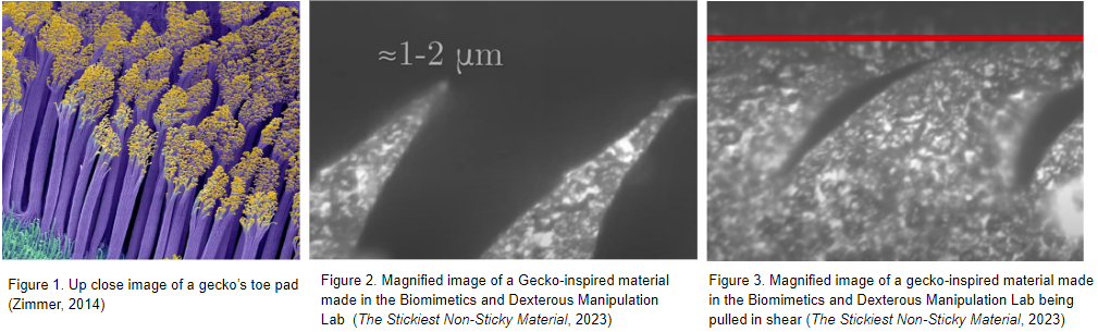
Geckos have millions of hairs called setae on their toe pads, the ends of each setae spread out into smaller hairs called spatula which are one twentieth the width of a human hair (Figure 1). These spatula spread out and bend when placed under load creating a large and almost perfect area of contact. Having such thin hairs also allows a gecko to stick to surfaces that are rough. Unlike a gecko’s toe pad, human-made adhesives are made with a wedge-shaped design (Figure 2) and are 5 times thicker, causing it to only be able to stick to smooth surfaces (U.S. National Science Foundation, 2011). The wedge design best creates an almost perfect contact area when pulled in the right direction (Figure 3). When it comes to engineering gecko-inspired adhesives, there are 7 functional properties: anisotropic attachment, attaches strongly with minimal preload, low detachment force, material independence, self-cleaning, anti-self matting, and a non-sticky default state (Autumn, 2007). Each of these properties allows a gecko to do its daily tasks without any complications.
Purpose
Today, commercial silicones are readily available to do-it-yourself makers and enthusiasts who are interested in creating silicone adhesives for robotic applications such as grippers. Hence, the primary goal of this project is to investigate the silicone-casting conditions that might make it possible in creating gecko-inspired adhesives at home without the need of industrial machinery.
Hypothesis
If silicone is casted on a ridged surface, such as a sheet of diffraction grating, the silicone will be able to withstand more shear force compared to one casted on a smooth surface because the silicone casted on a diffraction grating substrate provides a larger contact area when placed under load, similar to the millions of setae on a gecko’s toe pad.
Research
Types of gecko-inspired adhesive mechanisms
A few decades ago there were only two main forms of adhesive mechanisms, suction adhesion and magnetic adhesion (Sikdar et al., 2022). Suction adhesion works by using a pump to create a vacuum. Unfortunately Suction adhesion does not work on cracked or rough surfaces as it does not provide the necessary seal required to pull a vacuum. On the other hand magnetic adhesion uses magnets to climb allowing it to climb any ferromagnetic surface. Unfortunately this does limit the uses for magnetic adhesion as it can’t stick to any non ferromagnetic surfaces. Thankfully adhesive technologies have come a long way and we now have many new forms of adhesive technology. These include: dry fibrillar adhesion (the use of fibrils to make contact ), elastomeric adhesion (the use of elastomers to adhere), electrostatic adhesion (the use of positive and negative charges), and thermoplastic adhesion (the use of a solid material as an adhesive that keeps being reformed using heat).
How gecko-inspired materials are currently made in academic research labs
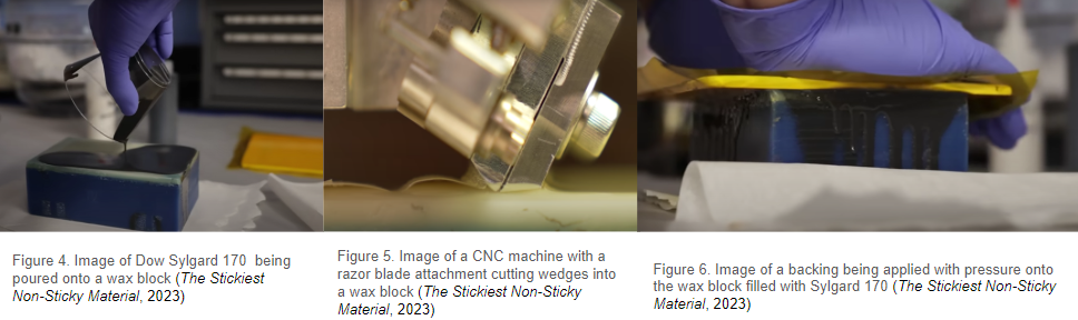
Most gecko-inspired adhesives fabricated in labs today are made of Polydimethylsiloxane (PDMS), a type of polymer known as an elastomer. PDMS needs to be degassed in a vacuum chamber before use as stirring it traps in air. To make gecko-inspired adhesives, the PDMS is first mixed and then degassed before being poured into a wax mould (Figure 4). This wax mould is special as it has micro wedges carved into it using an industrial CNC (Computer Numerical Control) machine with a razor blade attachment (Figure 5). Once the PDMS has been poured into the mould, a plastic backing is added by being pressed down onto the PDMS (Figure 6). This also pushes the PDMS into the wedges of the wax block. At last, the Polydimethylsiloxane is left in the mould to cure for at least 24 hours before it is removed and ready for use.
Characteristics of good gecko-inspired adhesives
There are many characteristics of a good adhesive. First, Young's modulus should be considered as it is the amount of force needed to bend, stretch, or deform a material. This is important as a material that has a very low Young's modulus value will cause the adhesive to stretch and lose contact area. In addition, a material that has too high of a Young's modulus value will rip while under load. Secondly, the detachment force should be low as a gecko should not need to use a large amount of force to remove its foot. Last but not least, gecko material should not rely on any wet adhesives like glue as over time it could degrade.
Rationale behind material choice
1. Silicone
Silicone starts out as a liquid and then hardens as it cures, this makes it very easy to work with while being good at replicating fine details. As well as being easy to work with, silicone does not permanently stick to anything but itself. This non-stick property is desirable as the use of a mould release spray could create unwanted small divots in the silicone, or fill in the wedges of the diffraction grating sheet. These benefits explain why the majority of gecko-inspired materials are made with silicone over materials such as thermoplastic elastomers (TPE) or carbon nanotubes.
There are two main types of room temperature vulcanising (RTV) silicone, platinum-cured and tin-cure. Tin-cure silicone uses a process called “condensation cure” which uses humidity in the air and tin as a catalyst to bond the molecules together. On the other hand, platinum-cured silicone uses a process called “addition cure”, which is the process of adding a catalyst such as platinum to the silicone base to get the molecules to bond together. Unlike the process of “condensation cure”, the process of “addition cure” does not create any toxins making it skin safe in most platinum-cured RTV silicone products.
2. Mould materials
In this experiment, gecko-inspired samples will be made by casting platinum-cured RTV silicone onto 3 different types of flat, smooth surfaces for comparison: diffraction grating, tempered glass, and acrylic.
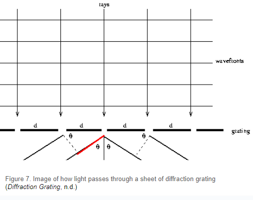
Diffraction gratings are mainly used in commercial settings with spectrometers, lasers, and other optical instruments. The function of these gratings' is to split white light into different sections of light by wavelength, thereby creating a rainbow or colorful-looking effect. The gratings are created by scratching the surface of a transparent material to create lines where the material will be opaque, and in between the opaque lines are small gaps that allow light through (Figure 7).
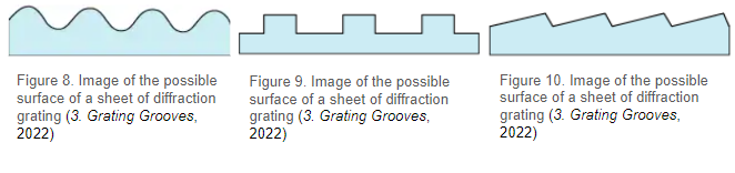
The process of scraping the transparent material will form ridges or wedges in the surface of the transparent material, these ridges or wedges can end up in a few different patterns (Figure 8, 9, 10). When compared to the ridges of the synthetic material made in a lab (Figure 11), you will see that the shape is similar.
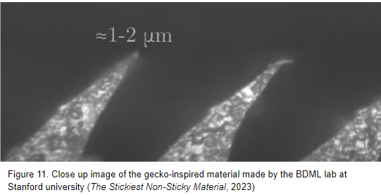
Hence, the main purpose of using the diffraction grating is to create lots of teeth-shaped wedges in the silicone, replicating the adhesion mechanism in gecko-inspired materials, without the use of any commercial machinery.
Variables
Independent variable:
-
Substrate Material (the bottom surface of the mould)
- 10mL of platinum-cured RTV silicone will be casted onto each of the 3 materials: a sheet of diffraction grating, a sheet of tempered glass, and a sheet of acrylic
Controlled variables:
-
Liquid amount of silicone used to make the test specimen
- The amount of silicone will be kept the same for each specimen that will be made as a weight difference may affect the accuracy of the results
-
Dimensions of the moulds
- The dimensions of the mould for each of the silicone specimens will be identical in order to give each specimen the same surface area
-
Type of silicone
- Platinum-cured RTV silicone will be used to make each specimen
- The ratio of hardener to base, will also be kept in a 1:1 ratio for each of the silicone specimens
-
Environment (temperature, humidity, and time)
- The temperature at which the specimens will be cured at will be 20 degrees centigrade in an indoor environment to keep away from wind and debris
- The silicone slabs will be cured for 24 hours before being demoulded and tested
Dependant variable:
-
Shear force
- The test of this project is to compare the shear force required to pull the three different silicone specimens off of a smooth flat surface i.e. glass
Procedure
Materials
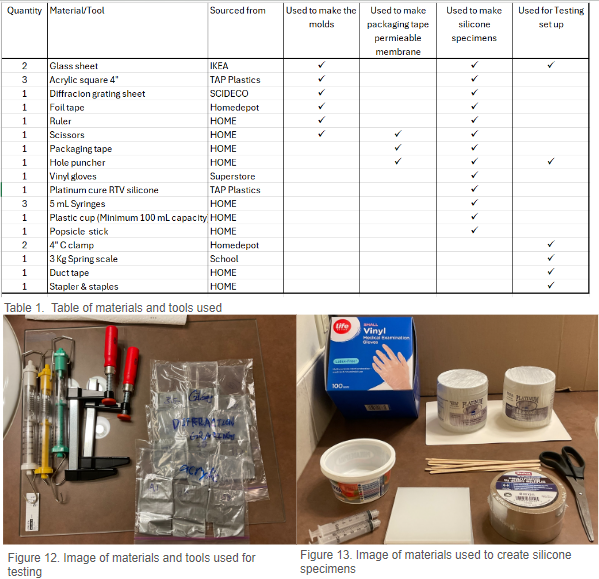
TAP Platinum silicone and 4” squares of CHEMCAST ecogreen acrylic were obtained from TAP Plastics (California, United States). NASHUA foil tape and BESSEY 4” C clamps were purchased from Homedepot (Calgary, Alberta), while the glass sheet was purchased from IKEA (Calgary, Alberta), and diffraction grating sheets were ordered from SCIDECO (Edmonton, Alberta).
Fabrication
Making the silicone test specimens is a three step process. The first step is to create 9, 2” by 3” moulds which will be used during the casting process. During the second step, 9 permeable packaging tape membranes are made and are hole punched 5 times. In the third and final step, 45 mL of silicone is mixed up and evenly distributed between the 9 moulds. They are then left to vulcanise for an hour before the packaging tape membranes are added and 45 more milliliters of silicone is evenly added to the 9 moulds. Once all of the silicone is poured, the moulds are left to vulcanise for 24 hours before use.
Fabrication materials and method
For the sample moulds
Materials and tools
- 1 Glass sheet
- 3 Acrylic squares (1/8”x4”x4”)
- 1 Diffraction grating sheet
- Foil tape
- Ruler
- Scissors
Method
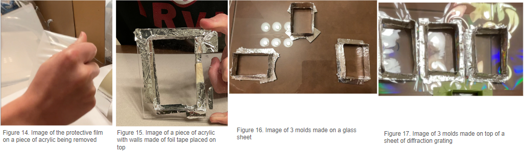
- Start by removing the protective piece of plastic film on one side of the acrylic square. (Figure 14)
- Use foil tape to make a 2” by 3” rectangular wall on top of the acrylic square. Make sure the foil tape is placed on the side without the plastic film (Figure 15).
- If needed place extra foil tape around the seams to seal the areas that could leak.
- Repeat steps 1-3 two more times for a total of three moulds.
- Next take the clean glass sheet and make three 2” by 3” rectangular walls (Figure 16).
- If needed, use extra foil tape to seal the areas around the mould that could leak. At this point there should be 6 moulds, 3 made on top of a square of acrylic, and 3 made on the glass sheet.
- For the final three moulds, use foil tape to make three 2” by 3” rectangular walls on top of a piece of diffraction grating (Figure 17).
- Once again, if needed, use extra foil tape to seal areas that could leak. There should be a total of 9 moulds at this point with 3 being on a piece of acrylic, 3 on a glass sheet, and 3 on a sheet of diffraction grating.
For the permeable membrane made of packaging tape
Materials and tools
- Packaging tape
- Hole puncher
Method
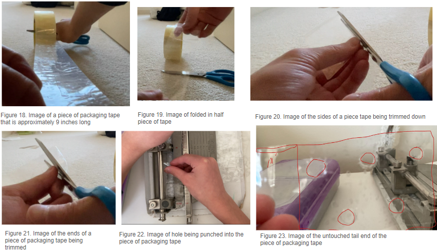
- Pull out a piece of packaging tape about 9 inches long (Figure 18).
- Fold the piece of packaging tape in half so the sticky sides are touching and the piece is still about 4.5” long (Figure 19).
- Now trim the edges of the piece of tape so there are no parts of the membrane where the stick part is revealed (Figure 20).
- Trim the 2 ends of the strip of packaging tape so there are no creases or air bubbles. This strip of packaging tape should still be approximately 4” long (Figure 21).
- Next, punch 5 holes each a quarter inch apart, into the strip of packaging tape (Figure 22). Make sure to leave at least an inch of space untouched from one of the tail ends (Figure 23).
- Now that 1 of the permeable membranes has been created, repeat steps 1-5 eight more times for a total of 9 packaging tape permeable membranes.
For the silicone samples
Materials and tools
-
Vinyl gloves
-
Platinum-Cured RTV Silicone
-
3 syringes (5 mL)
-
1 cup (minimum 100 mL capacity)
-
Popsicle sticks (for stirring)
-
Permeable membrane made of packaging tape
-
Moulds
Method
- Put on gloves
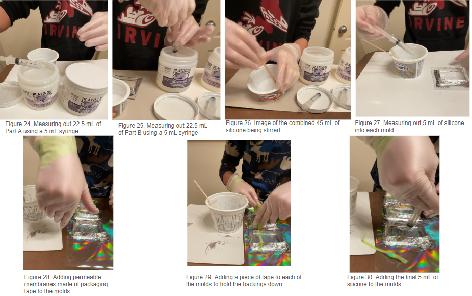
- Open up the jar of silicone labeled Part A and using a syringe measure out 22.5 mL into a plastic cup (Figure 24).
- Close the jar of silicone labeled Part A
- Open the jar of silicone labeled Part B and using a different syringe than the one used in step 2 measure out 22.5 mL into the same cup used during the first step (Figure 25).
- Close the jar of silicone labeled Part B
- Next using the popsicle stick stir the silicone in the cup for a minute (Figure 26).
- Using a clean syringe measure out 5 mL of silicone into each of the 9 moulds (Figure 27).
- Let the silicone cure for an hour and a half.
- Add a packaging tape permeable membrane to each of the 9 moulds making sure that there is a tail sticking out (Figure 28).
- Place a piece of tape on top of the tail end of the substrate to keep it pressed down (Figure 29).
- Repeat steps 2-6 to make 45 more milliliters of silicone.
- Using a syringe to add 5 more milliliters of silicone into each mould (Figure 30).
- Let the silicone cure for 24 hours before demoulding.
Testing
The test in this project is the shear force test, in which a specimen will be laid onto a clean, flat, sheet of glass and is pulled from the hole in the uncovered area of the packaging tape membrane.
Testing materials and method
Materials and tools
- Two 4-inch C-clamps
- A clean tempered glass surface for testing
- 3 kg spring scale
- Hole puncher
- Duct tape
- Stapler and staples
- Test specimens
Method
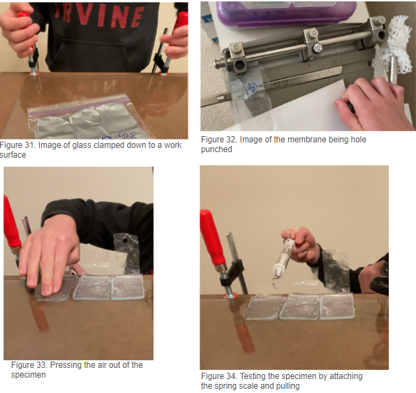
- Using 2 clamps, clamp the glass pane down to a work surface (Figure 31).
- Next, punch a hole in the area of the packaging tape membrane that is not encapsulated in silicone (Figure 32).
- Lay the specimen onto the glass surface and press the air out (Figure 33).
- Attach the spring scale and pull (Figure 34).
- Record the force in newtons required to pull the specimen off of the glass surface.
- Repeat steps 3-5 4 more times for the specimen making sure to clean the test surface periodically. If the specimen breaks and can no longer be used to get an accurate result then its test will be ended.
- Once the specimen either breaks or has completed its 5 pulls switch to another specimen and repeat steps 2-7 until all of the 9 specimens have either broken or completed their 5 pulls
- Record the data.
Observations
Prototype 1
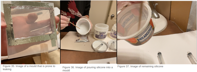
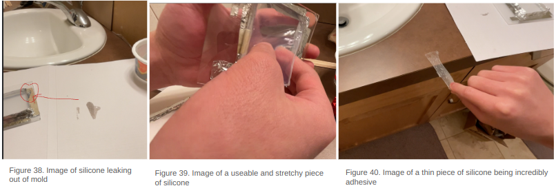
When the silicone arrived, I immediately started to make a mould out of popsicle sticks and foil tape. While making the walls of the mould, I realized that the popsicle sticks made it really hard to create a good seal at the corners of the mould (Figure 35). Reluctantly, I still mixed up a total of 40 mL of silicone and poured it into the mould (Figure 36). Immediately, I realised I had mixed up way too much silicone as it instantly filled up the entire mould with approximately 15 mL extra (Figure 37). The problems did not stop there though, as soon as the mould was filled, it started to leak out from the corners and there was nothing I could really do to stop it (Figure 38).
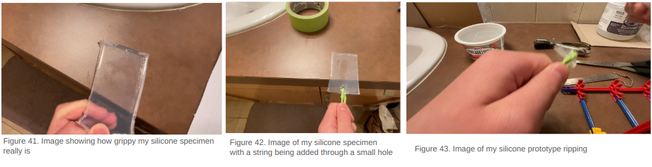
The next day when I demoulded the prototype, I was pleased to see that the mould only lost around 10 mL and the prototype was still intact and usable (Figure 39). I also noticed that the small thin bits of silicone that leaked out and cured were extremely sticky (Figure 40). While testing the prototype, I saw that it was very stretchy and could stick to practically any flat surface (Figure 41). Later, I tried to see if the silicone was prone to ripping so I cut a small hole in the piece of silicone and attached a piece of string to the prototype (Figure 42). I pulled gently and the silicone just ripped meaning that the silicone could not handle much force in one area (Figure 43).
Prototype 2
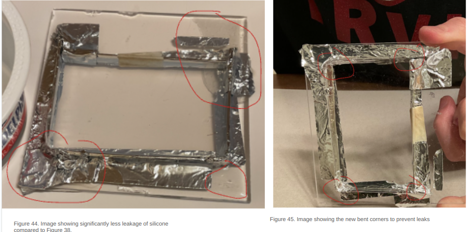
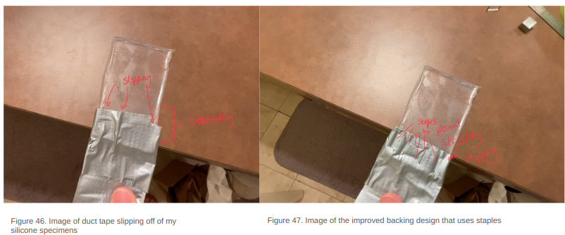
Given the issues with the first prototype, I decided to make a second prototype with the following changes: walls entirely made of foil tape, and using half as much silicone. These changes ended up working really well with the mould leaking a lot less silicone (Figure 44). This was because the foil tape walls could be bent to create a better seal (Figure 45). In addition to this success, the amount of silicone was also almost perfect as it could fill up the entire mould without having excess. Although the quality and properties of this prototype, once cured, was similar to that of the first prototype, the process of making it was much smoother and worry-free. Once I was done with comparing the two prototypes, I tried to attach a backing made of duct tape to prototype 2 and it immediately slipped off (Figure 46). So I tried using staples to attach the duct tape and it seemed to work (Figure 47).
Prototype 3
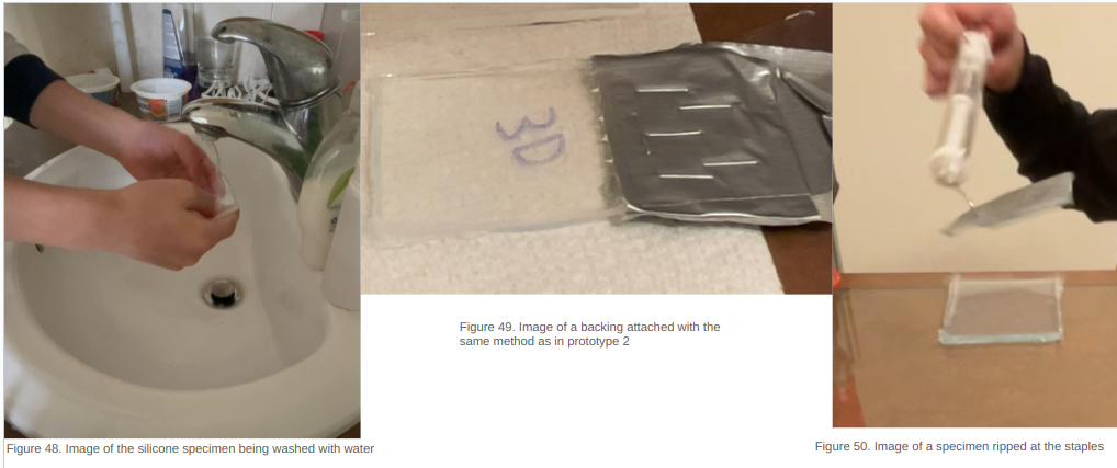
Feeling confident from how prototype 2 worked, I proceeded with making my 9 specimens. I spent more time on each mould trying to make it leak proof. Because I spent so much time on each mould, combined with the fact that thinner pieces of silicone seemed to be stickier, I decided to only give each specimen 10 mL of silicone. With this minor change, I made all of my moulds and specimens in the same way I made prototype 2. Once cured, I noticed that the specimens were very sticky but got dirty easily so I had to continually wash them with water and air-dry them (Figure 48). Also, I noticed that the specimens that were casted on diffraction grating had the same rainbow effect as a sheet of diffraction grating. Next, I attached the specimens to a duct tape backing using the same method as in prototype 2 (with staples) and tried testing them (Figure 49). There was one huge problem, all of my specimens ripped at the places where staples were placed (Figure 50). This meant that the staples were weakening the shear strength of the silicone and causing it to rip, this also meant that unfortunately for me, I had to find a new way to pull on my specimens, and make 9 more moulds.
Prototype 4
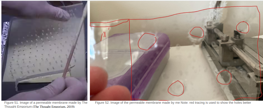
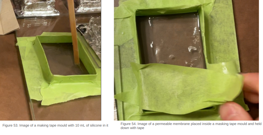
I remembered from a Youtube video I saw months ago where a permeable acrylic membrane was made to attach two sides of silicone together (Figure 51). So using that as inspiration, I made my own version of a permeable membrane using packaging tape with holes punched out (Figure 52). I had no knowledge if this would work so I made a mould out of masking tape and poured 10 mL of silicone into it (Figure 53). I carefully put the piece of packaging tape into the liquid silicone and used a piece of tape to keep it from rising to the surface (Figure 54).
After curing for 24 hours, I demoulded the prototype and noticed that the piece of packaging tape had been fully encapsulated. The bottom surface of the prototype was also extremely thin which could be a potential issue. I tested the prototype on my countertop and the specimen slid off the counter top without ripping. With the only issue remaining, being the varying thickness of the bottom layer, I decided that my only adaptation for the next and final prototype will be to pour half of the silicone first and let it cure for some time before adding the membrane and the other half of the silicone.
Prototype 5
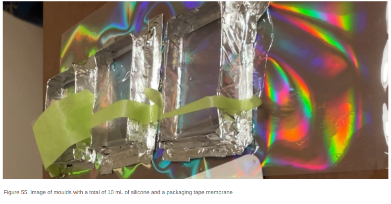
I created 9 moulds in the same way as prototype 4 and mixed up 45 mL of silicone to evenly spread between each of the 9 moulds. I left these to cure for one and a half hours before adding the permeable membranes and 45 more milliliters of silicone (Figure 55). The next day, I noticed that the specimens all had a thin bottom layer, and the ones casted on the sheet of diffraction grating did not have the rainbow effect I was hoping for. Nevertheless, the specimens were still very sticky and could all be tested.
Testing
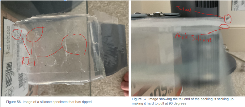
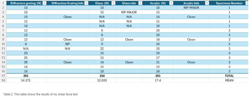
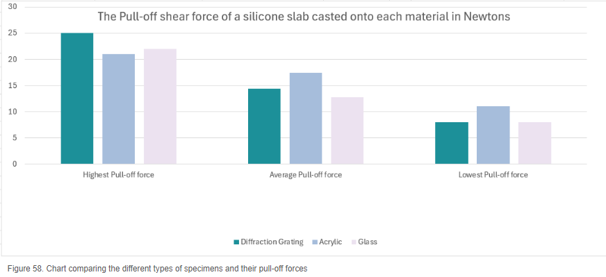
To test the specimens, I laid them onto the glass test surface, squeezed out the air and pulled with the spring scale. I noticed some of the specimens that had thinner bottoms were ripping (Figure 56), and those with a very thick bottom were hard to pull at exactly 90 degrees (Figure 57). Once I had my results, I could see that the specimens that were made by being casted on a glass sheet had performed considerably worse than those casted on diffraction grating and acrylic (Table 2). I also noticed that the specimens made by being casted on a sheet diffraction grating had lots of variability as one of the 3 specimens had the highest pull-off force, while the other two had lower shear force performance than those casted on the acrylic (Table 2).
Analysis
When comparing the average shear force each type of specimen could withstand, it is clear that the acrylic specimens performed the best with a 3 Newton lead over the diffraction grating specimens (Table 2). However just the average shear force does not tell the full story. From table 2, row 13 we can see that the specimen with the highest shear force recorded was actually casted on a sheet of diffraction grating. Then a question arises: Why didn’t the diffraction grating specimens have the highest score in the average shear force section? The answer to the question can be explained by looking at the furthest right column of Table 2 labeled “Specimen number”, from this column, one can see that all of the highest pull-off forces recorded in the diffraction grating column were provided by a specimen labeled 3 to represent specimen D3.
As the results show, D3 performed extremely well having a much higher shear force out of any other specimen made, and managed to show some consistent results. Unfortunately, unlike D3, the specimens D1 and D2 put up quite poor results, not even being able to outperform the glass specimens. Although this could be caused by specimens D1 and D2 being of lesser quality, this led to the average shear force being brought down from 19 Newtons to 14 Newtons.
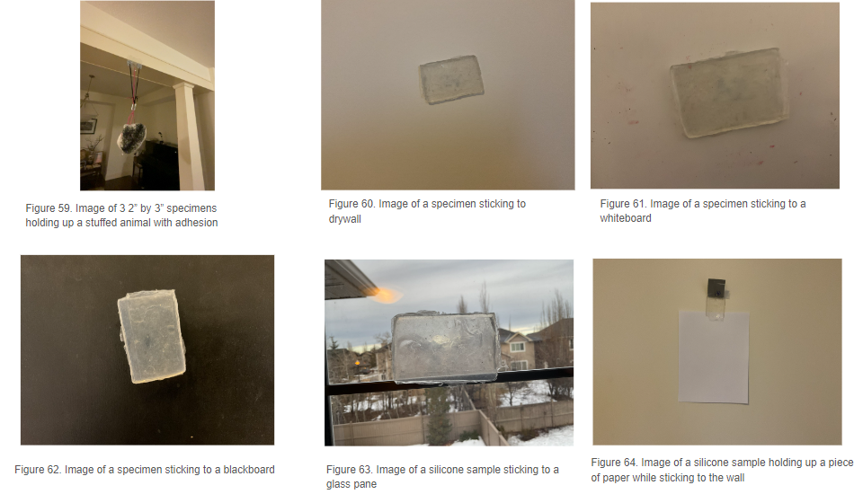
The decrease in the average shear force can more easily be seen in Figure 58 where both the highest pull-off force and the lowest pull-off force measurements are provided by the diffraction grating samples. From this information, I have been led to a discovery in which I have found that up to a certain point, the quality of the specimen matters more than the material it is casted on. In ideal fabrication conditions where all specimens demonstrate perfect consistencies, the material the specimen is casted on will matter.
Conclusion
The purpose of this project was achieved to make gecko-inspired adhesives with consumer level products and tools. As shown in Figure 59, with the use of three silicone specimens to produce enough adhesion, I was able to suspend a stuffed animal from a painted wood frame.
My hypothesis for this experiment was partially correct as it is clear from the test results that a well-made specimen casted on diffraction grating can withstand many Newtons of shear force. This could be beneficial for many different purposes such as a magnet alternative, or the soft gripper on a robot. It should be noted that further improvements should be made to the fabrication process to allow for specimens of a higher quality and consistency.
First of all, the time given for the first layer of silicone to cure should be extended by a few hours to prevent the permeable membrane from sinking and causing the specimens to have a thin bottom. Secondly, the diffraction gratings used in this experiment are not as rigid as the glass and acrylic allowing the diffraction grating to warp and bend. Perhaps it might be a good idea to attach the diffraction grating sheet onto a flat surface first before making the mould and then pouring silicone onto it. Thirdly, instead of adding the backing from above the mould, it would be easier to cut a small slit into the wall of the mould and slide the membrane into the mould from the side. Better yet, more advanced technology such as 3D printers could create leak proof moulds out of flexible materials such a TPE (thermoplastic elastomer) allowing for easy demoulding, and reducing the chance of damaging the specimens whilst removing from the moulds. In conclusion, my project has demonstrated that silicone can be casted on diffraction gratings to improve its shear force strength in a way that replicates a gecko’s toe pad.
Application
Although my specimens did not perform as well as those made with precision in university labs, I still tried to test their adhesive capabilities and see if they could carry other objects (Figure 59). From this test, I was pleasantly surprised to see that even the specimens that scored low in the shear force test could stick to a painted surface quite well. With this knowledge of my specimens' surprising adhesive performance on smooth painted surfaces, I wondered what else could these little things stick onto? Turns out it could stick to lots of different surfaces such as drywall (Figure 60), whiteboard (Figure 61), blackboard (Figure 62), and glass (Figure 63). From that point on, I tried to see if my specimens could suspend objects midair while adhering to these surfaces. I tried a few heavy objects first but was met with no success until I tried to attach a piece of paper and it worked (Figure 64). Eureka! This meant that my silicone specimens could be used in a similar way to a magnet or tape with the benefit of being washable, reusable, and being made of a soft material preventing damage to either the whiteboard or the floor below. On top of being able to be used as a magnet alternative, these silicone specimens can be added to robots to provide friction to a surface. Gecko-inspired adhesives can be used commercially in the biomedical field as an adhesive film or out in space to collect space junk.
Sources Of Error
In considering the possible sources of error in this experiment, one main thing stands out – human error. Any inaccuracy made by me during the fabrication process could cause imperfections in the specimens. Although the possible causes for imperfections have been prevented as much as possible, there are some noticeable physical differences with some of my specimens such as: the silicone being thicker in one area, the outside edges being rough due to struggles with the removal from the mould, and placement inconsistencies caused by the backing attachment method. Another area of possible sources of error is observed during the testing portion in which I am required to pull on the spring scale at a perfect 90 degree angle while simultaneously slowly increasing the force at which I am pulling. In this experiment, two crucial pieces of equipment used for measurements – spring scales and syringes – may have been inaccurate due to calibration errors.
Citations
3. Grating Grooves. (2022, January 20). Www.shimadzu.com. https://www.shimadzu.com/opt/guide/diffraction/04.html
02.What are Diffraction Gratings. (2018, December 10). Shimadzu.com. https://www.shimadzu.com/opt/guide/diffraction/02.html
AdhesionPublications | Biomimetics and Dextrous Manipulation Lab. (n.d.). Bdml.stanford.edu. http://bdml.stanford.edu/Main/AdhesionPublications
Comparison of Gecko-inspired Fibrillar Adhesives. (2024). Berkeley.edu. https://people.eecs.berkeley.edu/~ronf/Gecko/gecko-compare
Diffraction Grating. (n.d.). Www.physics.smu.edu. https://www.physics.smu.edu/~scalise/emmanual/diffraction/lab.html#:~:text=BACKGROUND
Fearing, R. (n.d.). Gecko Project. People.eecs.berkeley.edu. https://people.eecs.berkeley.edu/~ronf/Gecko/index.html
Fearing, R. (2016, May). Gecko Adhesion Bibliography. People.eecs.berkeley.edu. https://people.eecs.berkeley.edu/~ronf/Gecko/gecko-biblio.html#2003
Hawkes, E.W., Christensen, D.L., and Cutkosky, M.R., "Vertical Dry Adhesive Climbing with a 100x Bodyweight Payload," IEEE/ICRA 2015 (preprint).http://bdml.stanford.edu/uploads/Main/MicroTugs/ClimbingMicroTugsICRA2015.pdf
Interesting Gecko Adhesion Facts. (n.d.). People.eecs.berkeley.edu. https://people.eecs.berkeley.edu/~ronf/Gecko/gecko-facts.html
Krasnow, B. (2016, January 1). Making DIY gecko tape - work in progress. Www.youtube.com. https://www.youtube.com/watch?v=9XQfYKYO380&t=0s
Liu, L., Kuffel, K., Scott, D. K., Constantinescu, G., Chung, H.-J., & Rieger, J. (2017). Silicone-based adhesives for long-term skin application: cleaning protocols and their effect on peel strength. Biomedical Physics & Engineering Express, 4(1), 015004. https://doi.org/10.1088/2057-1976/aa91fb
Merriam-Webster Dictionary. (2023, July 22). Merriam-Webster.com. https://www.merriam-webster.com/dictionary/materials%20science#:~:text=%3A%20the%20scientific%20study%20of%20the
Molla-Storm, C. (2012, April 25). How to make PDMs - Sylgard 184 - Curing agent - Silicone elastomer. Www.youtube.com. https://www.youtube.com/watch?v=zWQTnH79l_8
M. Sitti and R.S. Fearing, ``Synthetic Gecko Foot-Hair Micro/Nano-Structures as Dry Adhesives,'' Journal of Adhesion Science and Technology, vol. 17, no.8, pp. 1055-1074, 2003.http://www.cs.cmu.edu/afs/cs/academic/class/15398-f04/www/readings/p1055.pdf
Multimedia Gallery - Climbing Robot Stickybot (Image 3) | NSF - National Science Foundation. (2011, February 11). Www.nsf.gov. https://www.nsf.gov/news/mmg/mmg_disp.jsp?med_id=69040
Nanjundaswamy , R. (n.d.). Biomimicry: Synthetic Gecko Tape by Nanomolding. https://nisenet.org/sites/default/files/catalog/uploads/4665/synthetic_gecko_tape_facilitated_activity.pdf
Sharpe, L. (1997, July 14). What exactly is the physical or chemical process that makes adhesive tape sticky? Scientific American. https://www.scientificamerican.com/article/what-exactly-is-the-physi/
Sikdar, S., Rahman, M. H., Siddaiah, A., & Menezes, P. L. (2022). Gecko-Inspired Adhesive Mechanisms and Adhesives for Robots—A Review. Robotics, 11(6), 143. https://doi.org/10.3390/robotics11060143
TAP Platinum Silicone. (2024). Tapplastics.com. https://www.tapplastics.com/product/mold_making_materials/mold_making_supplies/tap_platinum_silicone/494
The Stickiest Non-Sticky Material. (2023, January 23). Www.youtube.com. https://www.youtube.com/watch?v=vS0TuIPoeBs
The Thought Emporium. (2019). Climbing Walls With RAINBOWS - DIY Gecko Tape. In YouTube. https://www.youtube.com/watch?v=vpTX32KdVBQ
What are the major differences between tin-cure (condensation cure) and platinum-cure (addition cure) silicone mold making rubbers? (n.d.). Smooth-On, Inc. https://www.smooth-on.com/support/faq/184/
What is RTV-1 silicone? (n.d.). Elkem.com. https://www.elkem.com/products/silicones/rtv-1/
Young’s Modulus. (2020). Washington.edu. https://depts.washington.edu/matseed/mse_resources/Webpage/Biomaterials/young%27s_modulus.htm
Zimmer, C. (2014, June 8). Life Magnified. Science. https://www.nationalgeographic.com/science/article/life-magnified
(n.d.). https://www.cleveland.com/science/2012/09/university_of_akrons_research.html
Acknowledgement
I would like to thank Mr. Cheema of Colonel Irvine School for lending me the spring scales used in this project. In addition, I would like to thank my mom and sister for their support as this project would be nothing without them. Finally, I would like to thank my friend, Ernest T., for inspiring me and challenging me to take part in this year's science fair.