Homemade Adventure Of Electrodynamic Thrusters
Kamaleshwaran Vivekanandan
Grade 9
Presentation
Hypothesis
Question:
How does changing factors such as gap distance between two electrodes, the type of collector, or insulating the circuit affect ionic wind produced?
Hypothesis:
If the distance between the two electrodes increases, then the thrust will decrease because the strength of the electric field decreases. In the experiment, 1 cm would be the best distance to produce highest thrust(1 cm is the closest distance) because if you get any further closer, there will be electrical discharges, which will produce zero thrust. If I use the large copper which has a diameter of 3.1cm, then it will produce more thrust than the other metals because copper has a higher conductivity than all the other metals. Since it has a high electrical conductivity it allows for efficient transmission of electric current, which is important in EHD thrusters where electric fields are used to help ionize and propel/accelerate the air particles. If the EHD thruster is not insulated from outside external forces, then the thrust will decrease because it may the ionic might encounter some airflow resistance as it travels between the 2 electrodes.
Research
Overview
Electrohydrodynamic thrusters, EHD thrusters, is an asymmetrical electrode configuration, such as the pin-to-plate, to convert electrical energy to mechanical. This is asymmetrical because the electric field is more concentrated around the pin and weaker around the plate which is presented in Figure 1. The EHD thrust first requires the production of corona discharge because it is how ions are produced. The ionic wind and corona discharge is produced when an electrode has a sharp point(stronger electric field) called an emitter that creates ions in the gap that will accelerate toward the collector and along the way will bump into other neutral atoms and create wind. This works when there is a really strong electric field. Plasma is created and will propagate towards the opposite electrode based on the charge. The plasma will become a conductor for the electricity to pass through.
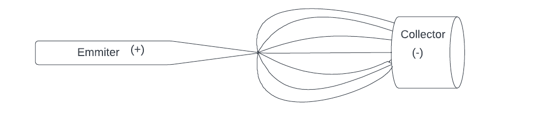
Figure 1: An Asymmetrical configuration of electrodes( emitter and collector)
The Process of Ionization
Since the air is the medium, blue light will be observed under certain dark conditions. The light(photons) is emitted when the neutral gas atoms get excited(go into a higher energy state) and relax (go to a lower energy state) which releases photons in the visible spectrum. Finally, the distance between the electrodes also affects the production of the Corona effect. If it is excessively spaced out, it can reduce the corona effect or won’t even be produced. This is known as the Biefeld-Brown effect. In 1965, Thomas Townsend Brown conducted an experiment along with Paul Alfred Biefeld, who was an astronomy professor, where they found out that when a high voltage is applied to an asymmetrical electrode circuit, it will produce thrust towards the negative electrode(the collector). According to Dr. Brown’s findings, the B-B Effect and the ionic wind can only work where there are at least 2 electrodes, one that acts like an emitter(positive) and the other functions as the collector(negative) and the presence of an ambient fluid(air).
The two electrodes will be separated. Usually, if there is a gap in a circuit, it is an open circuit, but the dielectric breakdown occurs in a circuit with a high voltage. Dielectric breakdown is when an insulating material fails to prevent current flow (in this experiment, air acts as the insulator). Dielectric breakdown only works if the material/insulator is electrically stressed when a high amount of voltage is applied. This amount of voltage is called the breakdown voltage and will create an electrical arc for the current to flow through. An electrical arc is a temporary passage for current to pass through an insulator. This phenomenon also occurs in nature during thunderstorms. A typical lightning has a voltage of 300 million volts. This is strong enough to break the insulating capacity of the air molecules(reaching the breakdown voltage). Paschen’s law is an equation that gives the breakdown voltage To produce an arc discharge under atmospheric conditions with a gap separation of 5cm, it requires at least 150 kv.
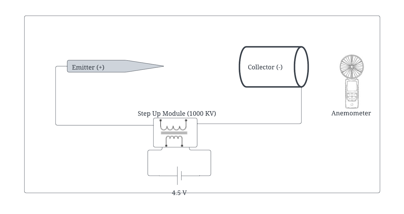
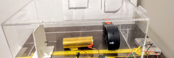
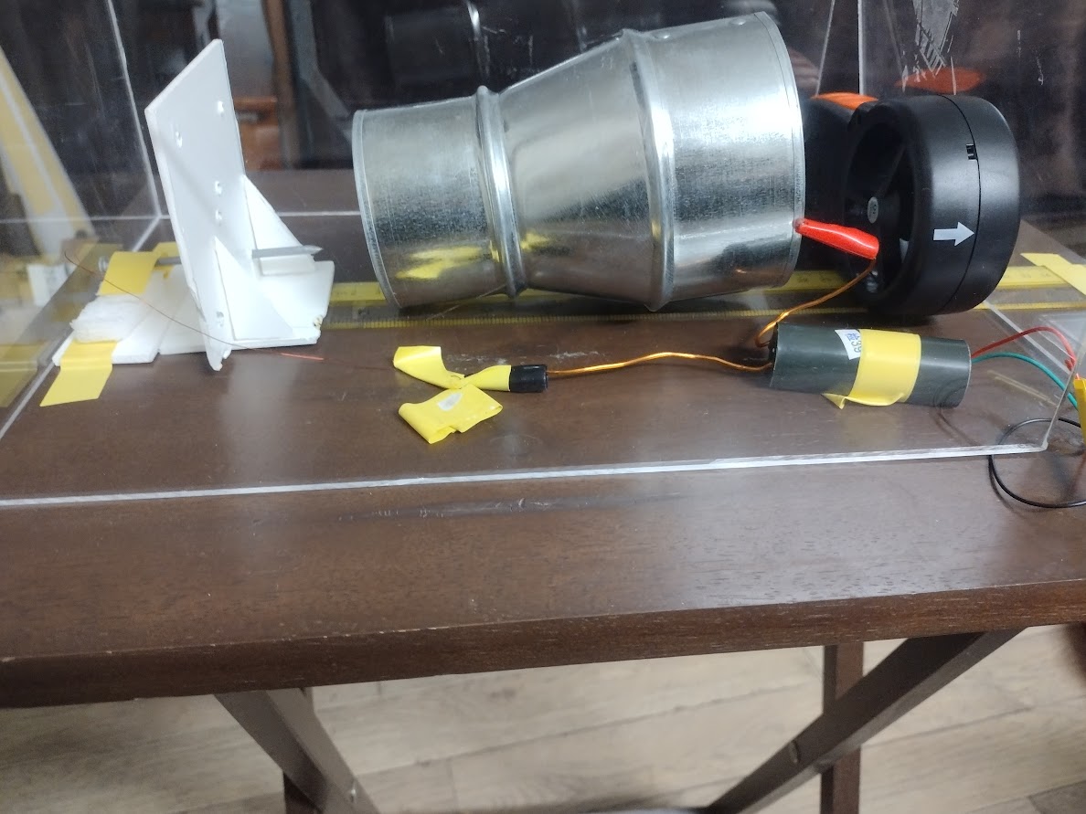
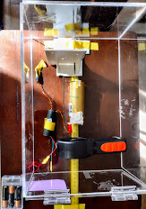
Figure 2: EHD setup
Creation of Thrust
In the pin to plate configuration of an EHD thruster, as shown in Figure 1, electrons go from the pin to the plate(emitter to collector). The field will be stronger around the emitter, strong enough to ionize the surrounding air particles but ripping electrons from the air. This will create positive ions which will attract the collector. When the ions are traveling toward the collector, there will be some ion-neutral collisions in between. The ions will transfer their momentum to the neutral atoms in the air. The net momentum will create an overall movement of the air particles, which in turn will create thrust as shown in Figure 1. As for the ions, they will be attracted by the collector. The thrust created will be measured in micro newtons. This is because 90% of the energy from the arc goes into heating the collector. A very small fraction goes into ionizing the air. Still, the pressure is so high at the atmospheric surface that all that immediately goes into collisions between the ions/electrons/neutrals that produce excitation and vibrations in the gas atoms. But if the collector is a hollow cylinder, there is a chance for some of the neutral atoms to make it through the tube. In this experiment the emitter is also called a cathode cathodes are positive(like emitters). The collector is called an anode because anodes are negative(like the collector).
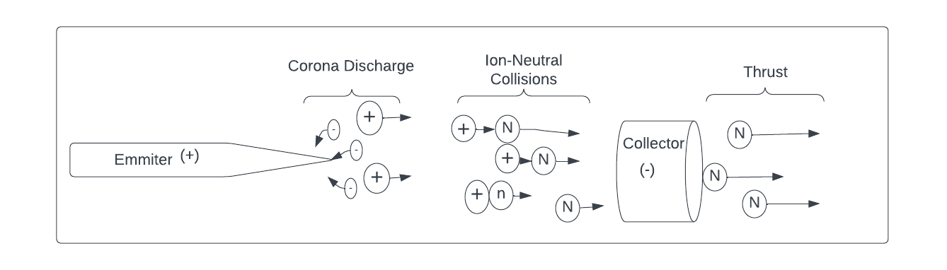
Figure 3: Production of thrust in an EHD thruster
Other Methods
Different types of electric propulsion devices are used to propel artificial spacecraft in space. NASA’s Double Asteroid Redirection Test(DART) Mission used an ionic thruster that helped accelerate the spacecraft at 14,000 km/hr before colliding with its targeted asteroid, Dimorphos. An ionic thruster works by ionizing a propellant(adding or losing an electron). The propellant is usually xenon because it is chemically inert and heavy, which will provide more thrust(Newton’s third law). Radon is also a good option for propellant because it shares they are both inert gasses, but radon is more expensive than xenon. An ionic thruster ionizes its fuel, which is neutral, through electron bombardment, which will cause the fuel to lose electrons and become positively charged. Since there is no overall charge, this condition is called a plasma. Using the help of electric and magnetic fields, the ions are expelled at speeds up to 144, 840 km/h.
Variables
Manipulated Variable:
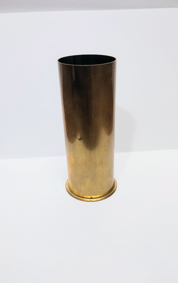
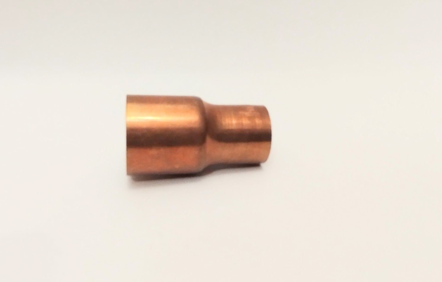
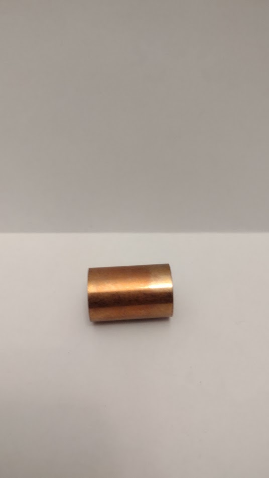
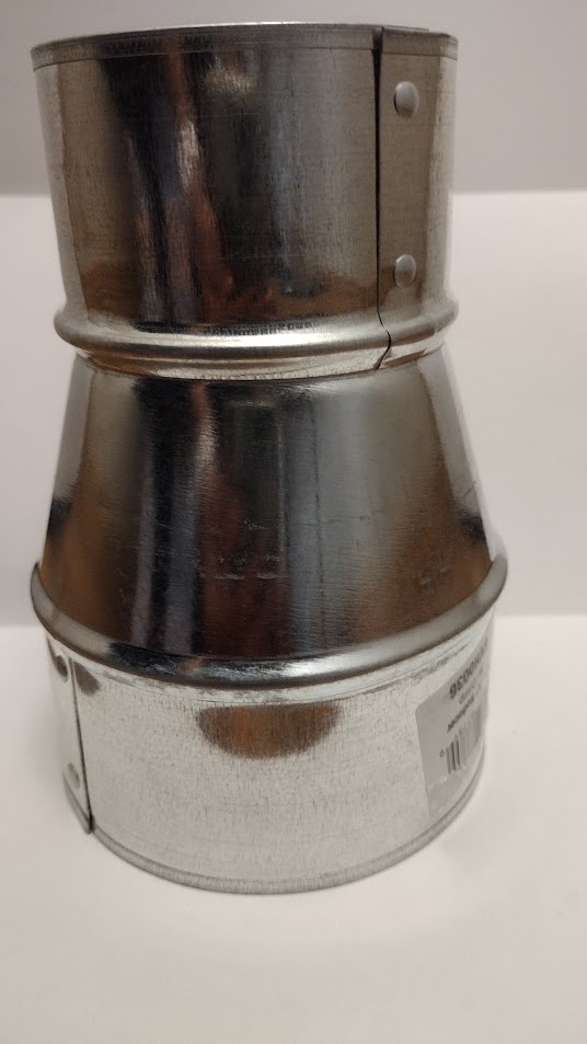
The manipulated variable in this experiment will be the factor that is changed throughout the experiment. In this project, there will be 4 manipulated variables. The first one is the material of the collector. I will be testing different metals that can be used as a collector and see which one will have the highest ionic wind speed. The metals will be copper, aluminum, galvanized brass and ungalvanized brass. Since the metals come in different shapes and sizes, my second manipulated variable will be the bass diameter of each of the tubes. Another variable that I will be testing is the distance between the two electrodes(collector and emitter). Finally, the last manipulated variable is the insulation around the entire setup and how having or not having an insulation can affect the ionic wind speed.
Controlled Variable:
A controlled variable in this experiment is something that is kept the same throughout the experiment to get reliable data. This experiment required 4 controlled variables. The first one is the distance between the back of the collector and the anemometer. Throughout the experiment, this distance has been maintained at 4 cm. Another variable that was kept the same is the power source. This experiment used AA alkaline batteries. Since this experiment required lots of energy, I had to switch the old batteries with the new ones. This follows up with the next controlled variable which was to maintain the same input voltage so each test gets the same amount of voltage. I tested the battery voltage by using a multimeter. Another variable is that the same emitter was used throughout every experiment meaning that the same nail was used for every test. Finally, location is my last controlled variable. This is where I would conduct the experiment in the same place, my living room.
Responding Variable
The last part of this experiment is my responding variable. This is my resulting data after every test. This would be the ionic wind speed collected by the anemometer that is placed behind the collector, where ionic wind would come out of.
Procedure
Materials:
-
3 AA battery(Costco)
-
e Electronics)
-
The type of metal can vary based on what is available at Home Depot
-
-
2 crocodile clips (Active Electronics Store)
-
Hot galvanized nails( 3 ½ in)
-
Mini Transformers(Active electronics)
-
Copper wire(Active electronics store).
-
Anemometer(Amazon)
-
Multimeter(Amazon)
-
Acrylic boards - 5(Acrylic & Paints)
-
2 10x30cm plastic boards(Active Electronics)
-
2 brasses(galvanized vs. galvanized)
-
Aluminum tube
-
3 copper tube sets
Procedure:
Part 1:
-
Construction steps:
-
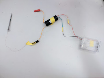
Connect the battery with the step-up module using the yellow conductive tape. In the step-up module, there will be two different colored wires, green and red. On the battery holder, a red and a black wire will be sticking out. Connect the red wire of the step-up module to the red wire of the battery holder. Then connect the black wire of the battery holder with the green wire of the step module.
-
Connect the two alligator clips to the 2 ends wires of the step-up module(they are dark yellow colored). Have one connected to the nail and the other to the end of the anode.
-
Cut out a 9x9 cm from the plastic board and drill 5 holes(4 in the corner and 1 in the center).
-
Cut out 4 right triangles and glue them to each bottom end(2 on the front, 2 on the back) or tape them to the base directly by sticking them to the edge of the table.
-
Choose the first anode for testing(the options are two brass tubes, one galvanized and the other not, 3 different-sized copper tubes, and the aluminum)
-
Depending on the anode chosen, the ends might look different in shape(one might have a larger diameter than the other). Choose 1 side to start with.
-
Align the nail to the center of the anode’s end.
-
Get a ruler(any size) and place it under the edge of the nail. Once carefully positioned, tape it to the base to prevent it from moving
Building Plexiglass:
-
Pour CH2Cl2 from the container onto the squeeze bottle. Fill it up to ½ of the squeeze bottle.
-
Place the 23x34cm board on the floor. Choose one of the 15x34 boards to start gluing. Make the 15x34 board stand at 90 degrees and touch the edge/side of the 23x34cm board.
-
Find something that has perfect 90 degrees like a sturdy box and place it behind the 15x34 so it stands with the support of the box.
-
Have someone hold the board securely and apply CHCl2 on the edge that separates the 2 boards. Don’t press on the squeeze bottle and let gravity help.
-
Repeat steps 2, 3, and 4 for the last 15x34cm board. If the bottle squeezer runs out of CH2Clc, refill only half of the bottle.
-
Choose one of the two 15x23 boards because one of them will contain the hinges
-
Flip the box over( the 23x34cm side facing upwards)
-
Place the hinges 3 cm away from the edge of both boards(the 23x34 board and the 15x23cm board). Mark it with a sharpie.
-
Apply CH2Cl2 on the bottom sides of the hinges. Have the 2 boards temporarily held by somebody else while the other person connects them with the hinges.
-
Using the remaining CHCl2(Methylene Chloride), apply it on the outside edges to make it more sturdy.
Conducting first experiment - Distance and Type of Collector:
-
Start the experiment by placing a tube 1cm away away from the edge of the nail
-
Place the anemometer 5 cm away from the other end of the tube. Turn on the switch and wait 5 seconds for the anemometer to read steadily. Repeat step 11 five times to show reproducible data.
-
Repeat step 2 but change the distance between the two collectors by 1cm.
-
Repeat steps 1-3 for all the metal tubes.
Conducting Experiment 2 - Enclosing the system:
This experiment can be conducted with the first one.
-
Choose any metal tube to test with.
-
While conducting the first experiment, add the plexiglass to see if it makes any difference. Repeat it again but this time, without the plexiglass.
Collecting Data
-
Make sure you test all you variables 5 times each
-
Once you've done that, find the mode of each set of expirement( Ex: Large Copper - 1cm: Mode is 0.9)
-
If you have two numbers that are equally reoccuring, find the middle number.(Ex: Mode = 0.7 and 0.6 = 0.65)
-
Safety
This project includes dealing with 1000kv(1 Megavolt) which is very dangerous and could be potentially fatal. This experiment has an electrocution and a fire hazard.
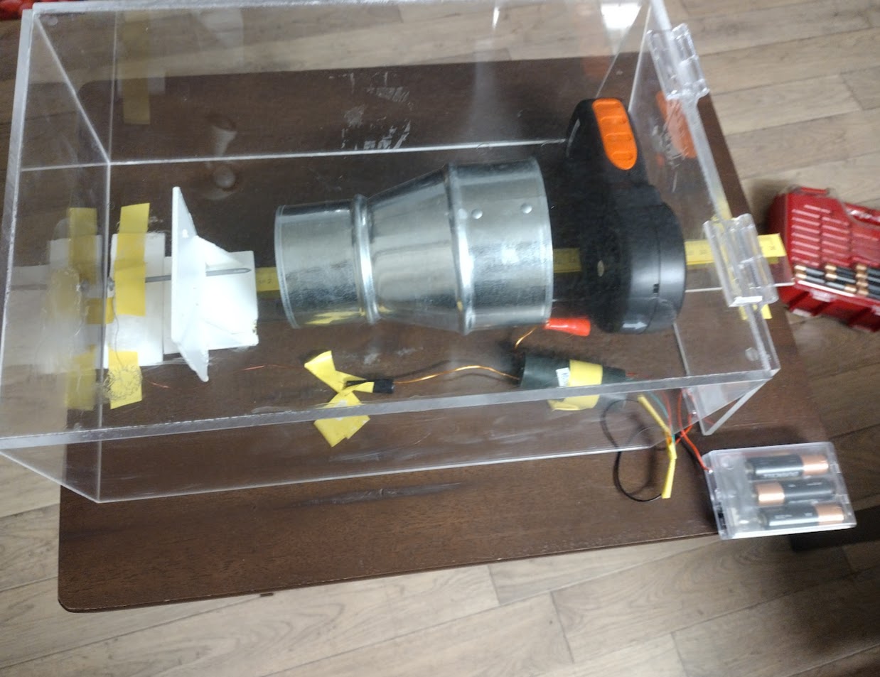
It is required to observe from a safe distance. It is also recommended by a professor at the University of Washington to enclose the setup with plexiglass. Plexiglass is a good insulator because it is made out of acrylic which can act as an insulator.
During the construction of the plexiglass, CH2Cl2(Methylene Chloride) was used as a way to stick the acrylic boards together. It is a corrosive material, and if it gets in the eyes, wash it away immediately. The side effects of not doing this will lead to either short or long-term blindness.
For self-protection, two things can be done. The first thing to do is maintain a good distance away from the setup like 4 meters. The second thing to do is wear flip-flops or shoes during the experiment. This will prevent the person from experimenting with the electrical grounding. While dealing with CH2Cl2, wear some form of eye protection such as goggles or glasses.
It is also important that another adult is present while experimenting. Along with that, it is important to not run the circuit for more than 15 seconds because the step-up module is not good at dissipating heat. This can lead to a fire hazard.
Observations
Ungalvanized Brass - Flat side
|
Distance(cm) |
#1 |
#2 |
#3 |
#4 |
#5 |
Mode |
|
1 |
0.5-0.6 |
0.5-0.6 |
0.5-0.6 |
0.5-0.4 |
0.5 |
0.5 |
|
2 |
0.6 |
0.6 |
0.6 |
0.5-0.6 |
0.5-0.6 |
0.6 |
|
3 |
0.5-0.6 |
0.5 |
0.6-0.5 |
0.6 |
0.5 |
0.5 |
|
4 |
0 |
0 |
0 |
0 |
0 |
0 |
|
5 |
0 |
0 |
0 |
0 |
0 |
0 |
Unglavanized Brass - Sharp Edge
|
Distance(cm) |
#1 |
#2 |
#3 |
#4 |
#5 |
Mode |
|
1 |
0.6-0.7 |
0.6-0.7 |
0.6-0.7 |
0.6-0.7 |
0.5-0.6 |
0.6 |
|
2 |
0.6 |
0.6 |
0.6-0.7 |
0.6 |
0.6 |
0.6 |
|
3 |
0.6 |
0.6 |
0.6 |
0.5-0.6 |
0.5-06 |
0.6 |
|
4 |
0.4-0.5 |
0.4 |
0.3 |
0.2 |
0.4 |
0.4 |
|
5 |
0.2 |
0.3 |
0.2 |
0.2-0.3 |
0.2 |
0.2 |
Galvanized Brass
|
Distance(cm) |
#1 |
#2 |
#3 |
#4 |
#5 |
Mode |
|
1 |
0.4 |
0.4 |
0.4 |
0.4 |
0.4 |
0.4 |
|
2 |
0.4-0.5 |
0.4-0.5 |
0.4 |
0.4 |
0.4-0.5 |
0.4 |
|
3 |
0.3-0.4 |
0.3 |
0.4 |
0.4 |
0.4 |
0.4 |
|
4 |
0.3 |
0.3 |
0.3 |
0.2 |
0.2 |
0.3 |
|
5 |
0 |
0 |
0 |
0 |
0 |
0 |
Large Copper
|
Distance(cm) |
#1 |
#2 |
#3 |
#4 |
#5 |
Mode |
|
1 |
0.9 |
0.9 |
0.9 |
0.9-0.8 |
0.9-0.8 |
0.9 |
|
2 |
0.6-0.7 |
0.6-0.7 |
0.6 |
0.6-0.7 |
0.6 |
0.6 |
|
3 |
0.6 |
0.6 |
0.6 |
0.5-0.6 |
0.6 |
0.6 |
|
4 |
0.2-0.1 |
0.1 |
0.3 |
0.2 |
0.2-0.1 |
0.2 |
|
5 |
0.1 |
0.0-0.1 |
0 |
0 |
0 |
0 |
Medium Copper
|
Distance(cm) |
#1 |
#2 |
#3 |
#4 |
#5 |
Mode |
|
1 |
0 |
0 |
0 |
0 |
0 |
0 |
|
2 |
0 |
0 |
0 |
0 |
0 |
0 |
|
3 |
0 |
0 |
0 |
0 |
0 |
0 |
|
4 |
0 |
0 |
0 |
0 |
0 |
0 |
|
5 |
0 |
0 |
0 |
0 |
0 |
0 |
Small Copper
|
Distance(cm) |
#1 |
#2 |
#3 |
#4 |
#5 |
Mode |
|
1 |
0 |
0 |
0 |
0 |
0 |
0 |
|
2 |
0 |
0 |
0 |
0 |
0 |
0 |
|
3 |
0 |
0 |
0 |
0 |
0 |
0 |
|
4 |
0 |
0 |
0 |
0 |
0 |
0 |
|
5 |
0 |
0 |
0 |
0 |
0 |
0 |
Aluminium Small Diameter
|
Distance(cm) |
#1 |
#2 |
#3 |
#4 |
#5 |
Mode |
|
1 |
0.4-0.5 |
0.4-0.5 |
0.4 |
0.4 |
0.4 |
0.4 |
|
2 |
0.3-0.2 |
0.3-0.2 |
0.3 |
0.3-0.4 |
0.3-0.2 |
0.3 |
|
3 |
0.1 |
0.2 |
0.2-0.1 |
0.2 |
0.3 |
0.2 |
|
4 |
0 |
0 |
0 |
0 |
0 |
0 |
|
5 |
0 |
0 |
0 |
0 |
0 |
0 |
Aluminum Large Diameter
|
Distance(cm) |
#1 |
#2 |
#3 |
#4 |
#5 |
Mode |
|
1 |
0.4 |
0.4 |
0.4 |
0.4 |
0.4 |
0.4 |
|
2 |
0.3-0.4 |
0.4 |
0.4 |
0.3-0.4 |
0.3-0.4 |
0.4 |
|
3 |
0.4 |
0.4 |
0.3 |
0.4 |
0.4 |
0.4 |
|
4 |
0.3 |
0.3-0.2 |
0.3-0.2 |
0.3 |
0.3 |
0.3 |
|
5 |
0.1 |
0.1 |
0.1 |
0.0-0.1 |
0.0-0.1 |
0.1 |
Aluminiu Large(No Insulation)

|
Distance(cm) |
#1 |
#2 |
#3 |
#4 |
#5 |
Mode |
|
1 |
0.4 |
0.5-0.6 |
0.4-0.5 |
0.4-0.5 |
0.4-0.5 |
0.4-0.5 |
|
2 |
0.4 |
0.4 |
0.4 |
0.4 |
0.4 |
0.4 |
|
3 |
0.4-0.5 |
0.4 |
0.4-0.5 |
0.4 |
0.4 |
0.4 |
|
4 |
0.4 |
0.4 |
0.4 |
0.4-0.3 |
0.4-0.3 |
0.4 |
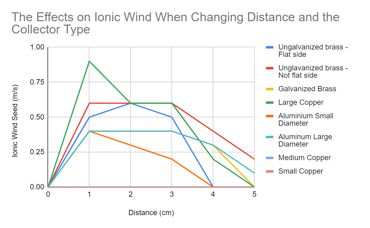
Figure 4: Wind speed vs Distance(d) plot
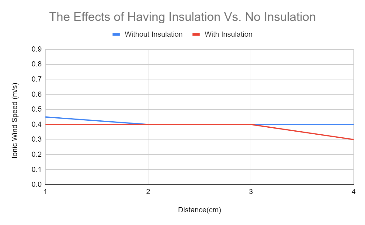
Figure 5: Wind speed vs Distance of an open vs closed acrylic box
Some interesting things were noticed while collecting the data. The first one is that if there wasn’t a conductive wire connected to the collector, the ionization process would still take place. This is weird to me because even though this is an open circuit, the nail still ionized the surrounding air. I think this happened because of the high voltage applied on the circuit, which could’ve cause current leakage when there was an opening.
Another thing that was noticed a charge was building next to the switch. Whenever I went to use the switch while the circuit was on, there would be small electrostatic discharges(ESD) that would contact my finger. This is called static electricity. This occurred due to the buildup of electrons next to the switch. The reason I believe this is happening is because since the nail is taking electrons from the surrounding air, and those electrons travel through the wire and are building up next to the switch. There are more than ESDs when I bring my finger close to it. Sometimes the strength and frequency of this phenomena can vary depending on what type of metal I am testing. For example, I noticed more ESDs when testing with copper(which produced the fastest ionic wind compared to the other metals).
Finally, when you are conducting the expirement in a low luminosity enviroment, you can see a blue-purple dot at the tip of the nail. This follows with my reserach and is called corona discharge whcih can be seen in Figure 8 down below.
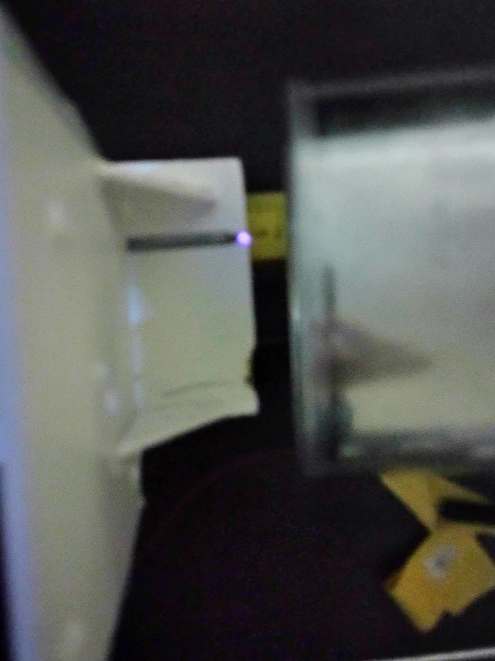
Figure 8: Corona Discharge(purple dot) taking place next to the nail.
Analysis
One trend that I noticed for the first experiment was that there was a disproportionate relationship with the distance between the electrodes and the speed of the ionic wind, which is that as the distance increased, the ionic wind speed decreased. Along with this observation, it is noticeable that when there is a gap distance between 1cm - 3cm, the ionic wind speed remains constant for most of the metals.
Another thing that I noticed is that the medium and small copper sizes didn’t produce any thrust. This shows that a collector has to have a certain diameter to produce out the back.
The metal aluminum had very consistent data meaning that even though the gap distance increased, the thrust produced didn’t change as much from the previous setting.
In the second part of the experiment, when the system was insulated, it produced the same data as for not having an insulation.
Conclusion
The results of the EHD thruster ionic wind speed collection experiment for various types of anodes and the effects of changing the distance of the electrodes can be seen in Figure 1. It can be observed that as the distance between the electrodes increases, the ionic wind speed decreases and this follows through with the hypothesis. The speed is decreasing because the strength of the electric field decreases. The mobility of ions depends on the strength of the electric field. In the equation E = V/D, where E is electric field strength, V is the voltage, and D is the distance between two electrodes. Since distance is inversely proportional, the electric field strength(E) will decrease. When this occurs, the process of ionization will be weaker meaning that fewer ions would be produced. Another reason why very little thrust is produced is because according to Dr. Dan Goebel from University of Washington, states that, “plasma produced from the emitter is unconfined”. This means that as the distance between the electrodes increases, the ion flux decreases, meaning, the amount of charged particles traveling in a certain area will decrease due to the ions spreading out, becoming more dispersed over a larger distance which can be shown in Figure 6.
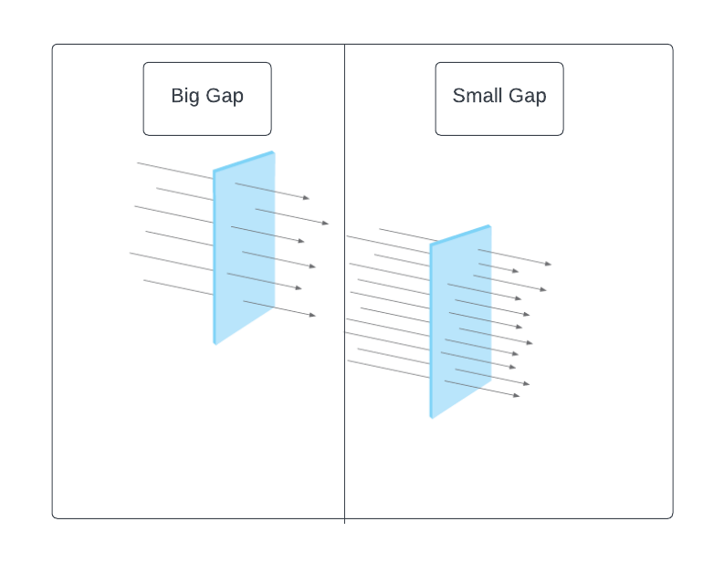
Figure 6: Ion Flux over increasing distance
The image on the left shows that when the electrodes are separated by a big gap, the ion flux decreases, so the particles are more dispersed and spread out. On the right, the arrows are more compact when the gap distance is small. This would lead to a higher electric field intensity(greater flux).
Sheldon, Robert. “What is flux in physics?” TechTarget, https://www.techtarget.com/whatis/definition/flux. Accessed 9 March 2024.
The other part of the hypothesis was proven correct when copper showed that it had the best performance out of all the other metals. It had a diameter of 3.1 cm on both sides when it was placed 1 cm away from the tip of the nail. It is larger than the other 2 copper tubes and those 2 didn’t produce any ionic wind. As stated before, copper has a high conductivity, the second most conductive metal to be exact. Since copper has a higher conductivity, it decreases the resistance, allowing a smooth and efficient current flow. This ensures that the electrical power is efficiently used in the circuit. Other metals like the brasses contain copper but also other atomic elements, decreasing its conductivity. This size of copper worked better than the smaller ones since the medium sized and the small sized copper didn’t produce any data. This shows that even if they are made out of the same material, the size of the collector can affect the thrust produced.
Finally, the last part of my expirement's hypothesis was proven incorrect as it shows that even if the circuit was insulated by an acrylic box, it would produce the same amount of thrust as not having any insulation.
Application
This experiment’s results will help with the usage of EHD thrusters in atmospheric conditions such as in future airplanes that require the utmost efficiency to replace loud turbines. Many factors affect the thrust’s power and its efficiency in the usage of electricity(energy source). This experiment helped to produce data that eliminated configurations or factors that might not be beneficial to the advancement of this technology in a non-laboratory condition such as usage of certain metals as collectors like brass or aluminum. This expirement also confirms that the smaller that gap distance between two electrodes, the faster the ionic thrust speed will be but when you get to close, you'll end up with only electric discharges but there won't be any ionic wind.
This expirement can also be a futuristic way to travel in space. If humans in the futre can find a way carry any form of gasseous medium(like air), you can use EHD thrusters as a way to propel yourself to your destination. This technology is way more efficient than today's combustion rockets because combustion rockets use most of their fuel reaching Earth's escape velocity(11.2m/s. This requires lots fuel so rockets tend to use up most of their fuel to leave the Earth's gravity and they mostly use gravity assist to get to their destination. Using technologies like EHD thrusters are very fuel efficient and that can accelerate a spacecraft to great speeds.
Sources Of Error
When testing this another time, I would have used an alternate power source like lithium batteries instead of AA alkaline batteries because lithium batteries can last longer. This is helpful because it prevents me from constantly changing batteries which in turn will create more reliable data since every test will receive consistent voltage as shown in Figure 7. Another thing I would have done differently is to have metals with the same diameter because then I could have more reliable data since the manipulated variable was the type of anode, not the size of the tube.
One source of error in this experiment is the protection from cosmic particles from space. These are high energetic particles form space that originate from gamma-ray bursts from stars, black holes, or even from our sun. One of these highly charged particles can actually ionize the surrounding air, creating unnecessary air flow which can vary my results.Though there is no practical way of preventing this, insulating the setup with cosmic shielding would produce gre
Another thing I would’ve done differently is to find a way of dissipating the heat from the step up module to make this circuit run longer and for safety concerns. Another reason why I would want to fix this when doing this expirement again is because it
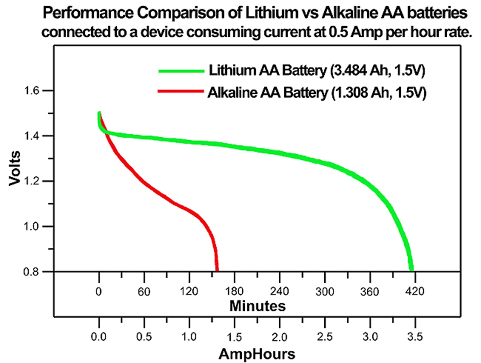
Figure 7: Efficiency of Lithium AA vs. Alkaline AA Battery
“Battery Life - Alkaline vs Lithium – SimpleAccess.” SimpleAccess, 24 August 2022, https://support.simpleaccess.com/hc/en-us/articles/6548180438163-Battery-Life-Alkaline-vs-Lithium. Accessed 14 March 2024.
Citations
American Galvanizers Association. (n.d.). What Is Hot-Dip Galvanizing? American Galvanizers Association. https://galvanizeit.org/hot-dip-galvanized-steel-for-parking-structures/hot-dip-galvanizing
Conventional Versus Electron Flow. (n.d.). All About Circuits. https://www.allaboutcircuits.com/textbook/direct-current/chpt-1/conventional-versus-electron-flow/
Ground Wire - What It Does and How It Works | Premium Electric. (2022, December 21). Premium Electric Ltd. Retrieved January 5, 2024, from https://www.premium-electric.ca/blog/ground-wire/
Hogg, M.G., Timoshkin, I.V., MacGregor, S. J., Wilson, M. P., Given, M. J., & T. Wang, T. (n.d.). ELECTRICAL BREAKDOWN OF SHORT NON-UNIFORM AIR GAPS.
International Sign Association. (n.d.). Power Line Safety. International Sign Association. https://signs.org/codes-regulations/federal-regulations/power-line-safety/
Jahn, R. G. (2006). Physics of Electric Propulsion. Dover Publications.
Lukas, J., Teel, G., Kolbeck, J., & Keidar, M. (2016). High thrust-to-power ratio micro-cathode arc thruster. AIP Advances, 6(2), 7. https://doi.org/10.1063/1.4942111
“Battery Life - Alkaline vs Lithium – SimpleAccess.” SimpleAccess, 24 August 2022, https://support.simpleaccess.com/hc/en-us/articles/6548180438163-Battery-Life-Alkaline-vs-Lithium. Accessed 14 March 2024.
PennState Material Research Institute. (n.d.). Dielectric Breakdown. PennState Material Research Institute. https://www.mri.psu.edu/materials-characterization-lab/characterization-techniques/electrical-characterization-lab-0
Tampa Steel & Supply. (n.d.). Which Metal is the Best Conductor of Electricity? Tampa Steel. Retrieved January 5, 2024, from https://tampasteel.com/best-metals-conduct-electricity/
Dobrijevic, Daisy. “NASA's DART asteroid-smashing mission: The ultimate guide.” 2022. Space News,
Cabanas, M. F., González, F. P., González, A. S., García, M. R., & Melero, M. G. (2022). Analysis of the Efficiency of the Electrohydrodynamic Propulsion Based on the Biefeld-Brown Effect for Manned and Unmanned Aircraft. Applied Sciences, 12(6), 2997. https://doi.org/10.3390/app12062997
Sheldon, Robert. “What is flux in physics?” TechTarget, https://www.techtarget.com/whatis/definition/flux. Accessed 9 March 2024.
Acknowledgement
I am forever grateful to Dr. Dan Goebel from NASA's Jet Propulsion Lab and Ph.D. student Emil Broemmelsiek, whose guidance and expertise have been invaluable in shaping my research and my understanding of this technology.