
DIY Portable Battery-Powered Hand Warmer
Mohammed Kasidwala
Grade 8
Presentation
Problem
Have your hands ever felt cold? If the aswer is yes, then your first instinct would have been to put on gloves. Unfortunatly, there is a problem with gloves. If you play winter sports like skiing or snoeshoeing, you will know that eventually, your hands start to freeze even with gloves on. The only options you have at that point is to stop and go inside, or use a hand warmer. The problem with using hand warmers though is that almost all of them require you to put them inside your pocket, whick isin't optimal as you would have to put your hands in your pockets for at least 10 minutes for your hands to warm up, and depending on what you are doing, that just might not be possible.
Another example of a situation where you would require a hand warmer is if you had Raynaud's phenominon, also called Raynaud's disease. This is where if your hands are cold, your blood vessels shrink and restrict blood flow. This is obviously not healthy and requires constant heating of the hand in cold places. With commertial hand warmers, you have to keep them in your pocket, and if you have Raynaud's phenominon, you can't just always keep your hands in your pocket, as you may need to use them. Also, if your hand warmer runs out of battery, you would have to go back inside, or to a warm place to charge it using a cable.
My DIY hand warmer solves all off these problems. My hand warmer can be strapped directly to your hands, eliminating the need to keep your hands in you pockets. It also runs on AA batteries, so they can be quickly swapped to give more battery life.
Method
How to make my hand warmer:
Materials:
- keyestudio NANO PLUS Development Board (ARDUINO)
- 4xAA Battery Pack w/ On/Off Switch
- 4xAA Batteries
- 5v Heating Pad
- 4.7kΩ 3980 NTE Thermistor
- 4.7kΩ 1/2W Resistor
- 3 Female to Bare Wire Breadboard Jumper Wires
- 3 Female to Female Breadboard Jumper Wires
- Copper Wire
- LR7843 Optocoupled N-MOSFET Module
- Cotton Glove
- Electrical Tape
- Packing Tape
Tools:
- Soldering Iron with Solder
- Soldering Mat (Optional)
- Hot Glue Gun
- Computer with ARDUINO IDE
- Wire Strippers
- Helping Hands (Optional)
- Screwdriver with #1 Phillips Head and #2 Flat Head
Code for ARDUINO:
Launch ARDUINO IDE and connect your ARDUINO to your computer via the USB cable. Follow this website for the instructions on how to set it up: https://wiki.keyestudio.com/KS0547_Keyestudio_NANO_PLUS_Development_Board_Compatible_with_Arduino_NANO(Black_and_Eco-friendly). Paste the following code into the editor:
#include <Arduino.h>
#define NTC_PIN A0 // Pin, to which the voltage divider is connected
#define VD_POWER_PIN 2 // 5V for the voltage divider
#define H_POWER_PIN 3 // 5V for activating MOSFET
#define NOMINAL_RESISTANCE 4700 // Resistance at 25°C
#define SAMPLING_RATE 5 // Number of samples measured
#define BETA 3980 // The beta coefficient of thermistor, Usually 3000 to 4000
#define RREF 4700 // Value of resistor used for the voltage divider
void setup() {
pinMode(VD_POWER_PIN, OUTPUT); // Allows pin to output 5V (for thermistor)
pinMode(H_POWER_PIN, OUTPUT); // Allows pin to output 5V (for MOSFET control)
Serial.begin(9600); // Initialize serial communication at a baud rate of 9600
}
void loop() {
float average = 0;
// Take voltage readings from the voltage divider
digitalWrite(VD_POWER_PIN, HIGH);
for (int i = 0; i < SAMPLING_RATE; i++) {
average += analogRead(NTC_PIN);
delay(10); // Sampling delay
}
digitalWrite(VD_POWER_PIN, LOW);
// Calculate average value of all samples
average /= SAMPLING_RATE;
// Calculate resistance
average = 1023 / average - 1;
average = RREF / average;
// Calculate temperature
float temperature = average / NOMINAL_RESISTANCE;
temperature = log(temperature);
temperature /= BETA;
temperature += 1.0 / (25 + 273.15);
temperature = 1.0 / temperature - 273.15; // Convert Kelvin to Celsius
Serial.print("Temperature: ");
Serial.print(temperature);
Serial.println(" *C");
// Control power state of warmer using hysteresis to prevent rapid switching
static bool heaterState = false; // Static variable to hold the heater state between function calls
if (temperature <= 35 && !heaterState) {
digitalWrite(H_POWER_PIN, HIGH); // Turn on the heater
heaterState = true;
Serial.println("Warmer on");
} else if (temperature >= 36 && heaterState) {
digitalWrite(H_POWER_PIN, LOW); // Turn off the heater
heaterState = false;
Serial.println("Warmer off");
}
// Calculate and print the total time elapsed since the program started in seconds
unsigned long secondsSinceStart = millis() / 1000;
Serial.print("Total time elapsed: ");
Serial.print(secondsSinceStart);
Serial.println(" seconds.");
Serial.println();
delay(2000); // Main loop delay
}
Click the arrow on the toolbar (top left) to upload the code to your ARDUINO. Then, open the serial monitor (heart rate monitor with magnifing glass, top right) and type in run to initialize the code. This only needs to be done once.
Assembly:
Step 1:
Solder a female to bare wire breadboard jumper wire (brown) and a copper wire to the negative lead from the battery pack.
Step 2:
Solder a female to bare wire breadboard jumper wire (gray) and a copper wire to the positive lead from the battery pack.
*Video corrupted, same steps as step 1*
Step 3:
Put ARDUINO in the foam packaging it came with and cut slits for the pins.
https://youtube.com/shorts/MwIGfSlDXeU?feature=share
Step 4:
Solder screw-on connections to MOSFET module. Unscrew the screws.
https://youtube.com/shorts/YUlo_gefuig?feature=share
Step 5:
Solder copper wires onto the heating pad power leads (1 wire per lead).
Step 6:
Twist the ends of the positive lead from the heating pad, and the copper wire on the positive lead from the battery pack. Insert into positive terminal on MOSFET. Tighten the corresponding screw firmly (#1 Phillips).
https://youtube.com/shorts/TKdgUHvLzVk?feature=share
Step 7:
Insert the copper wire attached to the negative lead from the battery pack into the negative terminal on the MOSFET. Also insert a short copper wire into the negativel terminal. Tighten the corresponding screw firmly (#1 Phillips).
https://youtube.com/shorts/xALMguBMc4s?feature=share
Step 8:
Insert the negative lead from the heating pad into the LOAD terminal on the MOSFET. Tighten the corresponding screw firmly (#1 Phillips). Then, wrap all the exposed wires attached to the MOSFET seperately with electrical tape.
https://youtube.com/shorts/MwzYtyB0bUA?feature=share
Step 9:
Insert one end of the 4.7kΩ resistor into a female-female breadboard jumper wire (black). Bend at a 90 degree angle for ease of use in step 12.
https://youtube.com/shorts/uB4yru1FRVg?feature=share
Step 10:
Insert the ends of the thermistor into 2 seperate female-female breadboard jumper wires (white, black with silver markings). Coil the 2nd end of the resistor in step 9 around the end of the thermistor with the white wire attached.
https://youtube.com/shorts/uB4yru1FRVg (at 20s)
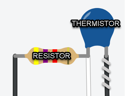
Step 11:
Hot glue all of the connections together from step 10. Make sure that the two legs of the thermistor do not touch each other. Ensure that the tip of the thermistor stays exposeed.
*Video corrupted, here is an image of what it should look like:
 *
*
Step 12:
Tape the thermistor to the heating pad using packing tape, making sure that the wires face the same way as the leads off of the heating pad. Also ensure that the tip of the thermistor is touching the heating pad directly. Apply enough to secure the thermistor firmly to the pad, but not enough to cover the entire pad with tape. Make sure not to allow the pad to curl, force it into a straightened position.
https://youtube.com/shorts/wcauVz_pKDg?feature=share
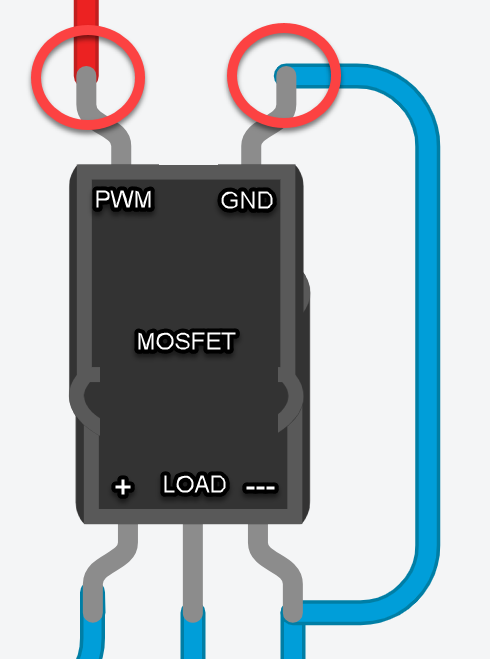
Step 13:
Insert the short copper wire from step 7 into the GND terminal on the MOSFET. Also insert a female to bare wire breadboard jumper wire (red) into the PWM terminal. Tighten both screws firmly (#2 Flathead).
https://youtube.com/shorts/dWXZlQhL5uE?feature=share
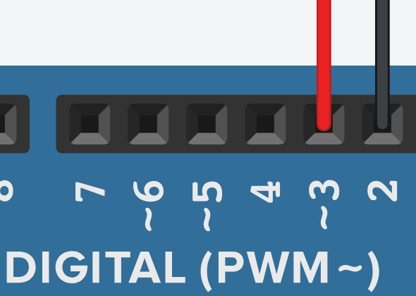
Step 14:
Plug in all connections to ARDUINO (breadboard jumper wires). Make sure ARDUINO is in slitted foam packaging, this is to protect the ARDUINO. Plug cables into ARDUINO through slits. The layout is as follows:
Brown - VIN or Vin
Gray - GND
White - A0
Black with silver markings - GND
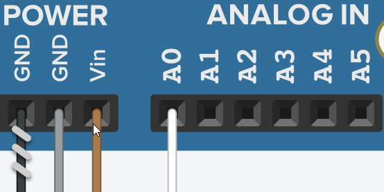
Red - 3 or D3
Black - 2 or D2
Step 15:
Place all components on top of the battery pack (side with power switch) and place the heating pad under the pack. Organize all of the wires and tape down the components (excluding heating pad) to the battery pack. Insert heating pad into cotton glove, where the pad can touch the back of the wearer's hand. Allow the battery pack module to rest on top of heating pad, outside of glove, can be secured using rubber bands around the battery pack module and the wearer's wrist.
https://youtube.com/shorts/nMaNEYQlhns?feature=share
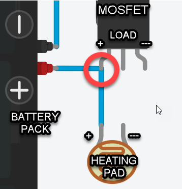
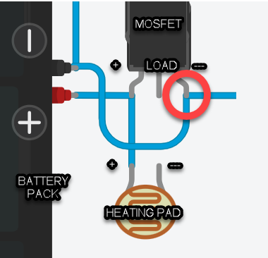
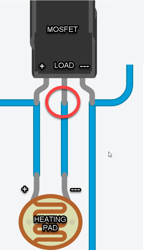
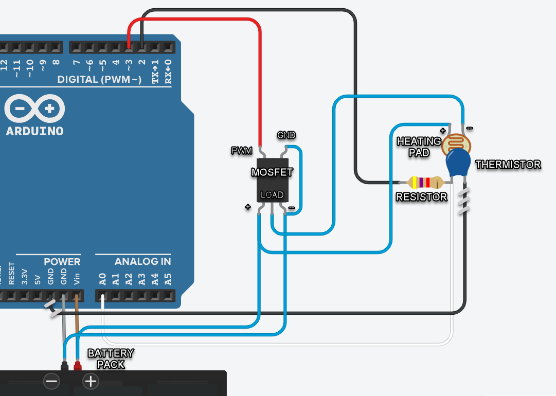
Full wiring diagram:
Analysis
The glove was placed in a room with an ambient temperature of 2 degrees Celcius. It was monitored using the ARDUINO IDE Serial Monitor, which relayed the tempertaure and time elapsed data to my computer. The warmer went from ambient (22C) to the threshold temperature (36C) in about 5 minutes and 11 seconds. The temperature fell from the threshold temperature (36C) to the restart temperature (35C) in about 46 seconds. The temperature rose back from the restart temperature (35C) to the threshold temperature (36C) in about 1 minute and 36 seconds.
Conclusion
- The warmer reached its threshold temperature (36C) from ambient (22C) in about 5 minutes and 11 seconds, and dropped to the restart temperature (35C) in about 46 seconds. The warmer returned to the threshold in about 1 minte and 36 seconds after hitting the restart temperature.
Citations
https://circuitdigest.com/microcontroller-projects/interfacing-Thermistor-with-arduino - For understanding how thermistors work, and to use the code to interface it with an ARDUINO
ARDUINO Website - As a function library for the code
Dave from Active Tech electronics store - Gave me advice on how to make the hand warmer
Acknowledgement
I acknowledge Dave from Active Tech electronics store for giving advice on how to go about making this hand warmer. I also acknowledge all sources mentioned in the citations.